EP0399237A2 - Dental appliance removal device - Google Patents
Dental appliance removal device Download PDFInfo
- Publication number
- EP0399237A2 EP0399237A2 EP90107950A EP90107950A EP0399237A2 EP 0399237 A2 EP0399237 A2 EP 0399237A2 EP 90107950 A EP90107950 A EP 90107950A EP 90107950 A EP90107950 A EP 90107950A EP 0399237 A2 EP0399237 A2 EP 0399237A2
- Authority
- EP
- European Patent Office
- Prior art keywords
- tooth
- crown
- tooth stump
- instrument
- opening
- Prior art date
- Legal status (The legal status is an assumption and is not a legal conclusion. Google has not performed a legal analysis and makes no representation as to the accuracy of the status listed.)
- Granted
Links
Images
Classifications
-
- A—HUMAN NECESSITIES
- A61—MEDICAL OR VETERINARY SCIENCE; HYGIENE
- A61C—DENTISTRY; APPARATUS OR METHODS FOR ORAL OR DENTAL HYGIENE
- A61C3/00—Dental tools or instruments
- A61C3/16—Dentists' forceps or clamps for removing crowns
-
- A—HUMAN NECESSITIES
- A61—MEDICAL OR VETERINARY SCIENCE; HYGIENE
- A61C—DENTISTRY; APPARATUS OR METHODS FOR ORAL OR DENTAL HYGIENE
- A61C3/00—Dental tools or instruments
- A61C3/16—Dentists' forceps or clamps for removing crowns
- A61C3/162—Dentists' forceps or clamps for removing crowns acting by leverage
Definitions
- the invention is based on an instrument for removing dentures connected to the tooth stump, with a handle and an extension piece formed on one end of the handle, which has an end piece which, in use, is inserted into an opening in a denture, the end piece has an edge that can be supported on the tooth stump and a surface section that can be brought into contact with surfaces of the dental prosthesis in the region of the opening.
- the bore is preferably designed as a bore with an oval cross section, this has the advantage that end piece shapes can be introduced into the bore, which can transmit a large torque to the crown to be lifted when the instrument is rotated and pivoted.
- the crown of a third molar can also be quickly removed from the tooth stump.
- the hole can be widened with a drill so that a larger end piece shape can be inserted between the crown and tooth stump. It is possible that the hole is a palatal or lingual hole. This has the advantage that the crown to lift off the tooth stump buccally, vestibularly does not have to be processed. Crown surfaces facing outwards that may be visible do not need to be drilled to remove the crown from the tooth stump. If shading that is not to be covered remains when soldering the hole, then as long as it only occurs on the inside of the tooth, it is not important when reusing this crown.
- the hole runs in the molar area between the occlusal surface of the denture and the tooth stump.
- premolars and molars large contact surfaces are created, which serve as a support for the end piece of the instrument with which the crown is to be detached from the tooth stump.
- Such a hole is easy to make, since the dentist can immediately see from the force with which he has to press the drill on the surface of the denture whether he is still piercing the crown shell or whether the drill tip is already in the area of the tooth stump.
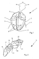
- Fig. 1 is shown a molar tooth, the tooth stump 2 wearing a crown 3.
- the crown margin is surrounded by gums 4.
- a side surface 5, palatal or lingual, and an occlusal surface is provided with a slot 7.
- the slot 7 is carried out in a known manner with a corresponding milling cutter. The crown is cut through to the tooth stump 2 in the area of the slot 7. If the crown 3 is to be removed from the tooth stump 2, the slot 7 is widened in the direction of the arrows 8 and 9 with corresponding known instruments, so that the crown detaches from the tooth stump 2.
- the crown 3 is so strongly deformed in this process that it only lies loosely on the tooth stump 2 and can be removed from the tooth stump 2 by means of pliers.
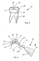
- FIG. 2 shows a bit section 15 with a canine tooth 16, a first premolar 17, a second premolar 18, a first molar 19 and a second molar 20.
- the second premolar 18 and the molars 19, 20 each wear a crown, which is provided with a drilling opening 21, 22, 23.
- the cross section of the bore opening 21, 22, 23 is circular to oval in FIG. 2.
- the boreholes of the borehole openings 21, 22, 23 run below the occlusal surface and end on the tooth stump plateau.
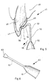
- Fig. 5 shows an incisor 45 with a tooth stump 46 and a crown 47, which is shown in section.
- the tooth stump is surrounded by gums 48 in the area of the crown edge.
- a bore 49 is made palatally or lingually, which extends from the inner surface of the crown 47 to the surface of the tooth stump 46.
- a crown lifter 50 with one end 51 can be guided into the bore 49.
- the end 51 is molded onto the extension piece 52 as a free end.
- the extension piece 52 merges into a handle 53.
- the extension piece 52 has a section 54 which is angled relative to the rest of the extension piece 52 and the handle 53.
- FIG. 6 shows a crown lifter 60, on the handle 61 of which an extension piece 62 is formed, which opens into an end piece 63.
- the plate-shaped end piece 63 is partially rectangular towards the end face and tapers in a trapezoidal or truncated cone shape towards the extension piece 62.
- the crown lifter 60 is preferably used in the molar region. The taper at the end piece 63 ensures that when the crown lifter 60 rotates in the region of the opening of a crown, it can be turned almost without torque.
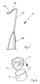
- FIG. 7 shows a further crown lifter 65 which, starting from a handle 66, merges into a first extension piece 67, to which a second extension piece 68 is connected.
- the second extension piece 68 is angled relative to the first extension piece 67.
- the second extension piece 68 merges into an end piece 69, which is crescent-shaped in the figure and tapers towards the free end.
- the crown lifter 65 is preferably used for lifting off crowns in the incisor area by inserting it into corresponding bores on the inside of the incisor, palatally or lingually, and pivoting it accordingly.
- FIG. 8 shows a tooth stump 70 from which a crown 71 has been lifted using the method according to the invention and a crown lifter according to the invention.
- the crown 71 was removed from the tooth stump 70 in the direction of the arrow 32 by inserting a crown lifter, for example the crown lifter shown in FIG. 6, into a bore 73.
- the Kro nenheber was rotated and pivoted in the hole 73 until the crown 71 has completely detached from the tooth stump 70 and can then be removed from the tooth stump 70.
Abstract
Description
Die Erfindung geht aus von einem Instrument zum Entfernen von mit dem Zahnstumpf verbundenem Zahnersatz, mit einem Griff und einem an einem Ende des Griffes angeformten Verlängerungsstück, das ein Endstück aufweist, das im Anwendungsfall in einen Durchbruch eines Zahnersatzes eingefügt ist, wobei das Endstück eine am Zahnstumpf abstützbare Kante und einen Flächenabschnitt aufweist, der im Bereich des Durchbruches an Flächen des Zahnersatzes zur Anlage bringbar ist.The invention is based on an instrument for removing dentures connected to the tooth stump, with a handle and an extension piece formed on one end of the handle, which has an end piece which, in use, is inserted into an opening in a denture, the end piece has an edge that can be supported on the tooth stump and a surface section that can be brought into contact with surfaces of the dental prosthesis in the region of the opening.
Ferner betrifft die Erfindung ein Verfahren zum Entfernen von einem mit einem oder mehreren Zahnstümpfen verbundenen Zahnersatz, der mittels eines Bohrers mit einem Durchbruch versehen wird, wobei zum Lösen des Zahnersatzes ein Instrument in den Durchbruch eingeführt wird, das aufgrund einer Schwenk-und/oder Drehbewegung den Zahnersatz vom Zahnstumpf löst, wobei der Durchbruch als mindestens eine Bohrung mit einem beliebigen Querschnitt ausgeführt wird, die sich von der Oberfläche einer Zahnersatzseitenfläche ausgehend in Richtung eines Zahnstumpfes erstreckt.The invention further relates to a method for removing a dental prosthesis connected to one or more tooth stumps, which is provided with an opening by means of a drill, an instrument being inserted into the opening to release the dental prosthesis, which is caused by a pivoting and / or rotating movement detaches the denture from the tooth stump, the opening being designed as at least one hole with an arbitrary cross section, which extends from the surface of a denture side surface in the direction of a tooth stump.
Ein derartiges Verfahren sowie ein zur Durchführung des Verfahrens geeignetes Instrument ist durch die DE-OS 33 30 572 sowie FR 25 22 494 A1 bekanntgeworden.Such a method and an instrument suitable for carrying out the method have become known from DE-OS 33 30 572 and FR 25 22 494 A1.
Der bekannte Kronenaufbiegemeißel ermöglicht ein bequemes Aufbiegen der Kronen. Ferner werden zum Aufbiegen der Kronen nicht mehr unterschiedlich ausgeformte instrumente benötigt.The well-known crown bending tool enables the crowns to be easily bent open. Furthermore, differently shaped instruments are no longer required to bend the crowns open.
Mit dem bekannten Kronenaufbiegemeißel können Kronen gut aufgebogen werden, sofern sie mindestens über zwei Flächen vorher aufgetrennt wurden. In Bezug auf die Vorbearbeitung einer Krone, d.h. um sie vom Zahnstumpf abziehen zu können, bringt der bekannte Kronenaufbiegemeißel keine Verbesserungen. Die Krone muß auch für den Einsatz des bekannten Kronenaufbiegemeißels weit geschlitzt werden. Dies ist nicht nur zeitaufwendig, sondern häufig wird dabei auch der für den Arbeitsvorgang verwendete Bohrer, meist Diamantbohrer, beschädigt. Bedeutender ist aber noch, daß durch die Auftrennung und Aufbiegung, die Krone vielfach so stark beschädigt wird, daß sie nicht mehr wiederverwendet werden kann. Zudem ist der Aufwand, die gelegten Schlitze wieder so zu verlöten, daß der Kronenoberfläche der Trennvorgang nicht anzusehen ist, groß und zeitaufwendig.With the known crown bending tool, crowns can be bent open, provided that they have been separated at least over two surfaces beforehand. With regard to the pre-processing of a crown, ie in order to be able to pull it off the tooth stump, the known crown bending tool does not bring any improvements. The crown must also be widely slit for the use of the known crown bending tool. This is not only time-consuming, but often the drill used for the work process, usually a diamond drill, is also damaged. Is more important but still that due to the separation and bending, the crown is often damaged so much that it can no longer be reused. In addition, the effort to solder the slots again so that the crown surface of the separation process is not visible, is large and time-consuming.
Der aus der FR 25 22 494 A1 bekanntgewordene Kronenheber besteht aus einem Griff, an den sich ein Verlängerungsschaft anschließt und der in ein sich verjüngendes Ende übergeht. Das Ende ist gegenüber dem Verlängerungsschaft abgewinkelt. Der Verlängerungsschaft ist wie das Ende im wesentlichen im Querschnitt kreisförmig. Soll mittels des bekannten Kronenhebers eine Krone oder ein Stiftzahn von einem Zahnstumpf abgehoben werden, so ist die Krone zwischen Okklusionsfläche und Zahnstumpfplateau anzubohren. In die geschaffene Öffnung kann der bekannte Kronenheber eingeführt werden und indem der Griff des Kronenhebers verdreht wird, kann über eine Schwenkbewegung die Krone bzw. der Stiftzahn vom Zahnstumpf gelöst werden.The crown lifter, which became known from
Mit dem bekannten Kronenheber können auf den Zahnersatz nur aus Drehbewegungen resultierende Verschwenkbewegungen übertragen werden. Dabei kann der zu lösende Zahnersatz im Bereich des Durchbruchs stark deformiert werden. Ferner ist der bekannte Kronenheber für ein Abheben des Zahnersatzes im Schneidezahnbereich ungeeignet.With the known crown lifter, only pivoting movements resulting from rotary movements can be transferred to the dentures. The dentures to be detached can be severely deformed in the area of the opening. Furthermore, the known crown lifter is unsuitable for lifting the dentures in the incisor region.
Der Erfindung liegt daher die Aufgabe zugrunde, ein Instrument und ein Verfahren der eingangs genannten Art dahingehend weiterzubilden, daß zu entfernender Zahnersatz mit nur geringsten Beschädigungen vom Zahnstumpf oder den Zahnstümpfen schnell und einfach gelöst werden kann.The invention is therefore based on the object of developing an instrument and a method of the type mentioned in such a way that dental prostheses to be removed can be removed quickly and easily with only minimal damage to the tooth stump or the tooth stumps.
Diese Aufgabe wird erfindungsgemäß dadurch gelöst, daß das Endstück plattenförmig, bevorzugt rechteckförmig, ausgebildet ist, und sich bevorzugt zum Verlängerungsstück hin verjüngt. Weiterhin wird die Aufgabe auch dadurch gelöst, daß das Endstück mondsichelförmig ausgebildet ist.This object is achieved in that the end piece is plate-shaped, preferably rectangular, and preferably tapers towards the extension piece. Furthermore, the object is also achieved in that the end piece is crescent-shaped.
Im Backenzahnbereich wird das Instrument zum Lösen des Zahnersatzes so eingesetzt, daß es im Bereich des Durchbruches nahezu drehmomentenfrei gedreht werden kann, und daß es im Bereich eines Zahnstumpfplateaus, der Auflagefläche, durch die Drehbewegung des Instrumentes Normalkräfte auf die zur Okklusionsfläche diametralen Fläche übertragen kann.In the molar area, the instrument is used to loosen the denture in such a way that it can be rotated almost without torque in the area of the breakthrough, and that it can transmit normal forces to the area diametrical to the occlusal surface in the area of a tooth stump plateau, the contact surface, by the rotary movement of the instrument.
Im Schneidezahnbereich wird das erfindungsgemäße Instrument in eine Bohrung eingeführt, die an der Zahnstumpfseitenfläche endet und zum Lösen des Zahnersatzes muß ein Ende des Instruments mit der Spitze am Zahnstumpf zur Anlage gebracht werden.In the incisor region, the instrument according to the invention is inserted into a bore which ends on the tooth stump side surface and one end of the instrument must be brought into contact with the tooth stump in order to detach the tooth replacement.
Weiterhin wird die Aufgabe auch dadurch gelöst, daß das Endstück eine am Zahnstumpf abstützbare Kante und einen Flächenabschnitt aufweist, der im Bereich des Durchbruchs an Flächen des Zahnersatzes zur Anlage bringbar ist.Furthermore, the object is also achieved in that the end piece has an edge which can be supported on the tooth stump and a surface section which can be brought into contact with surfaces of the dental prosthesis in the region of the opening.
Das erfindungsgemäße Verfahren hat damit den wesentlichen Vorteil, daß der abzunehmende Zahnersatz, z. B. eine Krone, nicht mehr mit langen Schlitzen versehen werden muß. Eine Bohrung mit einem vorzugsweise ovalen Querschnitt ist ausreichend, um mit geeigneten Instrumenten die Krone vom sie haltenden Zahnstumpf abzulösen. Die Bohrung hat gegenüber den bekannten Verfahren einen kleinen freien Querschnitt, d.h. sie ist schnell anzubringen und der dabei verwendete Bohrer wird nur geringen Belastungen ausgesetzt. Bohrer, die für den Bohrvorgang des erfindungsgemäßen Verfahrens verwendet werden, haben eine längere Lebensdauer, können für eine Vielzahl von Bohrungen an Kronen eingesetzt werden, während derselbe Bohrer schon beim Aufschlitzen einer Krone nach dem bekannten Verfahren so stark beschädigt werden kann, daß er für weitere Verwendungen unbrauchbar ist.The method according to the invention thus has the essential advantage that the dentures to be removed, for. B. a crown, no longer has to be provided with long slots. A hole with a preferably oval cross section is sufficient to detach the crown from the tooth stump holding it with suitable instruments. Compared to the known methods, the bore has a small free cross section, ie it can be installed quickly and the drill used is only subjected to low loads. Drills used for the drilling process of the Method used according to the invention have a longer life, can be used for a variety of holes on crowns, while the same drill can be damaged so badly when slitting a crown by the known method that it is unusable for further uses.
Ein weiterer Vorteil ist, daß eine abzuhebende Krone nicht mehr verformt werden muß. Bis auf die Bohrung bleibt die ursprüngliche Form der Krone auch dann erhalten, wenn sie vom Zahnstumpf abgezogen wird. Dies ermöglicht in hohem Maße eine Wiederverwendung der Krone. Es werden Kosten eingespart. Der mit der abgezogenen Krone sich beschäftigende Zahntechniker muß bei der Krone, die nach dem erfindungsgemäßen Verfahren vom Zahnstumpf entfernt wurde, nur die gelegte Bohrung wiederverlöten. Ein Zurückbiegen von Kronenseitenhälften in die ursprüngliche Zahnkronenform entfällt. Das unter großem Zeitaufwand erfolgende Zulöten der sich lang erstreckenden Schlitze bei Kronen, die nach dem bekannten Verfahren vom Zahnstumpf abgehoben wurden, ist nicht mehr notwendig.Another advantage is that a crown to be lifted no longer has to be deformed. Except for the hole, the original shape of the crown is retained even if it is pulled off the tooth stump. This enables the crown to be reused to a high degree. Costs are saved. The dental technician dealing with the removed crown only has to re-solder the drilled hole in the crown which was removed from the tooth stump by the method according to the invention. There is no need to bend crown side halves back into the original tooth crown shape. The soldering of the long slots in crowns, which were lifted from the tooth stump according to the known method, is no longer necessary.
Ist die Bohrung bevorzugt als Bohrung mit einem ovalen Querschnitt ausgeführt, so hat dies den Vorteil, daß Endstückformen in die Bohrung eingeführt werden können, die bei Dreh- und Schwenkbewegungen des Instruments ein großes Drehmoment auf die abzuhebende Krone übertragen können. Auch die Krone eines dritten Molares läßt sich damit schnell vom Zahnstumpf lösen. Je nach Haftung der Krone am Zahnstumpf kann die Bohrung mit einem Bohrer noch aufgeweitet werden, damit eine größere Endstückform zwischen Krone und Zahnstumpf eingeführt werden kann. Dabei ist es möglich, daß die Bohrung eine palatinale oder linguale Bohröffnung ist. Dies hat den Vorteil, daß die Krone zum Abheben vom Zahnstumpf bukal, vestibulär nicht bearbeitet werden muß. Nach außen gerichtete Kronenflächen, die sichtbar sein können, müssen nicht angebohrt werden, um die Krone vom Zahnstumpf lösen zu können. Sollten beim Verlöten der Bohrung nicht zu überdeckende Schattierungen zurückbleiben, so sind diese, solange sie nur auf der Zahninnenseite auftreten, bei einer Wiederverwendung dieser Krone nicht von Bedeutung.If the bore is preferably designed as a bore with an oval cross section, this has the advantage that end piece shapes can be introduced into the bore, which can transmit a large torque to the crown to be lifted when the instrument is rotated and pivoted. The crown of a third molar can also be quickly removed from the tooth stump. Depending on the adhesion of the crown to the tooth stump, the hole can be widened with a drill so that a larger end piece shape can be inserted between the crown and tooth stump. It is possible that the hole is a palatal or lingual hole. This has the advantage that the crown to lift off the tooth stump buccally, vestibularly does not have to be processed. Crown surfaces facing outwards that may be visible do not need to be drilled to remove the crown from the tooth stump. If shading that is not to be covered remains when soldering the hole, then as long as it only occurs on the inside of the tooth, it is not important when reusing this crown.
Die Bohrung verläuft im Backenzahnbereich zwischen der Okklusionsfläche des Zahnersatzes und dem Zahnstumpf. Bei Prämolaren und Molaren werden große Auflageflächen geschaffen, die dem Endstück des Instruments, mit dem die Krone vom Zahnstumpf gelöst werden soll, als Auflage dient. Eine derartige Bohrung ist einfach zu legen, da der Zahnarzt am Kraftaufwand, mit dem er den Bohrer an die Zahnersatzoberfläche zu drücken hat, sofort erkennen kann, ob er noch den Kronenmantel durchbohrt, oder ob sich die Bohrerspitze schon im Bereich des Zahnstumpfes befindet.The hole runs in the molar area between the occlusal surface of the denture and the tooth stump. With premolars and molars, large contact surfaces are created, which serve as a support for the end piece of the instrument with which the crown is to be detached from the tooth stump. Such a hole is easy to make, since the dentist can immediately see from the force with which he has to press the drill on the surface of the denture whether he is still piercing the crown shell or whether the drill tip is already in the area of the tooth stump.
Im Bereich der Schneidezähne endet die Bohrung an der Zahnstumpfseitenfläche.In the area of the incisors, the bore ends on the side of the tooth stump.
Dies hat den Vorteil, daß auch Kronen von Zahnstümpfen der Schneidezähne leicht gelöst werden können. Der Zahnstumpf dient der Stirnfläche oder Spitze des Endstückes des Instruments als Widerlager und mittels einer Schwenkbewegung des Instruments kann auf die Krone eine Kraft in Richtung Zahnachse bewirkt werden. Die Bohrung ist auf der Zahnkronenseiteninnenfläche so anzubringen, daß die Spitze eines Instruments zum Lockern der Krone leicht in die Bohrung einzuführen ist und am Zahnstumpf unverrückbar zur Anlage gebracht werden kann.This has the advantage that crowns of tooth stumps of the incisors can be easily removed. The tooth stump serves as an abutment for the end face or tip of the end piece of the instrument and a force in the direction of the tooth axis can be exerted on the crown by means of a pivoting movement of the instrument. The hole is to be drilled on the inner side of the tooth crown in such a way that the tip of an instrument for loosening the crown can be easily inserted into the hole and immovably brought into contact with the tooth stump.
Die Bohrung weist bevorzugt eine Breite von b = 4 mm, eine Höhe von h = 2 mm und eine Tiefe, je nach Größe des Zahnersatzes, von t = 2 mm bis t = 6 mm auf.The bore preferably has a width of b = 4 mm, a height of h = 2 mm and a depth, depending on the size of the denture, from t = 2 mm to t = 6 mm.
Dies hat den Vorteil, daß mittels eines verhaltnismäßig kleinen Durchbruchs an der Krone, die Zahnkrone vom Zahnstumpf abgelöst werden kann. Der in seinen Abmessungen angegebene Bohrungsquerschnitt und Bohrlochtiefe ist ausreichend, um die Zahnkrone mit erfindungsgemäßen Instrumenten vom Zahnstumpf abzuheben.This has the advantage that the tooth crown can be detached from the tooth stump by means of a relatively small opening on the crown. The dimensions of the bore cross-section and the depth of the borehole are sufficient to lift the tooth crown from the tooth stump with instruments according to the invention.
In einer bevorzugten Ausgestaltung der Erfindung ist das Endstück mondsichelförmig ausgebildet.In a preferred embodiment of the invention, the end piece is crescent-shaped.
Dies hat den Vorteil, daß über Schwenkbewegungen des Kronenhebers ein Kraftschluß an Schneidezähnen erreicht werden kann, der dazu ausreicht, Zahnkronen auch von Zahnstümpfen der Schneidezähne abzulösen.This has the advantage that frictional engagement of the incisors can be achieved by pivoting the crown lifter, which is sufficient to detach tooth crowns from tooth stumps of the incisors.
In weiterer Ausgestaltung der Erfindung geht das Endstück in einen Abschnitt des Verlängerungsstückes über, der gegenüber dem übrigen Verlängerungsstück und dem Griff abgewinkelt ist.In a further embodiment of the invention, the end piece merges into a section of the extension piece which is angled relative to the rest of the extension piece and the handle.
Dies hat den Vorteil, daß der erfindungsgemäße Kronenheber auch dann eingesetzt werden kann und mit ihm ausreichende Hebelkräfte erzeugt werden können, wenn die Bohrung über die Mundöffnung nicht direkt für das Instrument zugänglich ist.This has the advantage that the crown lifter according to the invention can also be used and sufficient leverage can be generated with it if the bore is not directly accessible to the instrument via the mouth opening.
Das erfindungsgemäße Verfahren und das erfindungsgemäße Instrument entspricht damit allen erweiterten Anforderungen, die im Bereich der Zahnprothetik gestellt werden. Die Bohrung an der Krone ist schnell und einfach zu legen, die Zahnkrone wird dabei nur geringfügig beschädigt und erfährt auch keine Verfor mungen. Die Bohrung läßt sich mit wenig Aufwand wieder so verschließen, daß sie nicht mehr erkennbar ist. Die entfernte Krone kann als vollwertige neue Krone wiederverwertet werden.The method according to the invention and the instrument according to the invention thus meet all the expanded requirements that are placed in the field of dental prosthetics. The hole in the crown is quick and easy to place, the tooth crown is only slightly damaged and is not deformed mung. The hole can be closed again with little effort so that it is no longer recognizable. The removed crown can be reused as a full new crown.
Weitere Vorteile ergeben sich aus der Beschreibung und der beigefügten Zeichnung. Ebenso können die vorstehend genannten und die noch weiter aufgeführten Merkmale erfindungsgemäß jeweils einzeln oder in beliebigen Kombinationen miteinander verwendet werden. Die erwähnten Ausführungsformen sind nicht als abschließende Aufzählung zu verstehen, sondern haben vielmehr beispielhaften Charakter.Further advantages result from the description and the attached drawing. Likewise, the features mentioned above and those listed further can be used according to the invention individually or in any combination with one another. The mentioned embodiments are not to be understood as an exhaustive list, but rather have an exemplary character.
Die Erfindung ist in der Zeichnung dargestellt und wird anhand von Ausführungsbeispielen in der Zeichnung näher erläutert. es zeigen:
- Fig. 1 einen Backenzahn mit einer auf zwei Seiten aufgeschlitzten Krone nach einem bekannten Verfahren;
- Fig. 2 einen Gebißabschnitt mit Bohrungsöffnungen nach dem erfindungsgemäßen Verfahren;
- Fig. 3 einen Backenzahn mit Zahnkrone und Bohrung nach dem erfindungsgemäßen Verfahren;
- Fig. 4 einen Zahnstumpf gemäß Fig. 3, mit einem erfindungsgemäßen Kronenheber, dessen Endstück auf dem Zahnstumpf aufliegt;
- Fig. 5 einen Schneidezahn mit einer Zahnkrone im Schnitt und einem erfindungsgemäßen Kronenheber;
- Fig. 6 einen erfindungsgemäßen Kronenheber;
- Fig. 7 eine weitere Ausführungsform eines erfindungsgemäßen Kronenhebers;
- Fig. 8 die Form einer Krone nach dem Abheben von einem Zahnstumpf nach dem erfindungsgemäßen Verfahren mit einem erfindungsgemäßen Kronenheber.
- 1 shows a molar tooth with a crown slit on two sides by a known method;
- 2 shows a bit section with bore openings according to the method according to the invention;
- 3 shows a molar tooth with a tooth crown and a bore according to the method according to the invention;
- FIG. 4 shows a tooth stump according to FIG. 3, with a crown lifter according to the invention, the end piece of which rests on the tooth stump;
- 5 shows an incisor with a tooth crown in section and a crown lifter according to the invention;
- 6 shows a crown lifter according to the invention;
- 7 shows a further embodiment of a crown lifter according to the invention;
- Fig. 8 shows the shape of a crown after lifting off a tooth stump according to the inventive method with a crown lifter according to the invention.
Die einzelnen Figuren der Zeichnung zeigen den erfindungsgemäßen Gegenstand teilweise stark schematisiert und sind nicht maßstäblich zu verstehen. Die Gegenstände der einzelnen Figuren sind teilweise im Verhältnis zueinander stark vergrößert dargestellt, damit ihr Aufbau besser gezeigt werden kann.The individual figures of the drawing show the subject of the invention in a highly schematic manner and are not to be understood to scale. The objects of the individual figures are partially shown greatly enlarged in relation to each other, so that their structure can be shown better.
In Fig. 1 ist mit 1 ein Backenzahn gezeigt, dessen Zahnstumpf 2 eine Krone 3 trägt. Der Kronenrand ist von Zahnfleisch 4 umgeben. Eine Seitenfläche 5, palatinal oder lingual, und eine Okklusionsfläche ist mit einem Schlitz 7 versehen. Der Schlitz 7 wird in bekannter Weise mit einem entsprechenden Fräser ausgeführt. Die Krone wird im Bereich des Schlitzes 7 bis auf den Zahnstumpf 2 durchtrennt. Soll die Krone 3 vom Zahnstumpf 2 abgenommen werden, so wird mit entsprechenden bekannten Instrumenten der Schlitz 7 in Pfeilrichtung 8 und 9 aufgeweitet, so daß sich die Krone von dem Zahnstumpf 2 löst. Die Krone 3 wird bei diesem Vorgang so stark verformt, daß sie nur noch lose auf dem Zahnstumpf 2 aufliegt und mittels einer Zange von dem Zahnstumpf 2 abgenommen werden kann.In Fig. 1, 1 is shown a molar tooth, the
Fig. 2 zeigt einen Gebißabschnitt 15 mit einem Eckzahn 16, einem ersten Prämolar 17, einem zweiten Prämolar 18, einem ersten Molar 19 und einem zweiten Molar 20. Der zweite Prämolar 18 und die Molaren 19, 20 tragen jeweils eine Krone, die mit einer Bohröffnung 21, 22, 23 versehen ist. Der Querschnitt der Bohrungsöffnung 21, 22, 23 ist in der Fig. 2 kreisförmig bis oval. Die Bohrlöcher der Bohrungsöffnungen 21, 22, 23 verlaufen unterhalb der Okklusionsfläche und enden auf dem Zahnstumpfplateau.FIG. 2 shows a
Fig. 3 zeigt einen Backenzahn 25, mit einer Krone 26 auf einem Zahnstumpf 27. Von dem Backenzahn 25 ist auch die Wurzel 28 in der Figur dargestellt. Der Zahnstumpf 27 ist in gestrichelten Linien in der Figur eingezeichnet. Die Krone 26 ist mit einer Bohrung 29 versehen, die eine Kronenseitenwand durchbricht und einen ovalen Querschnitt aufweist. Die Bohrung 29 ist unterhalb der Okklusionsfläche 30 angelegt und verläuft dicht über einer Auflagefläche 31 des Zahnstumpfes 27. Die Bohrung 29 verläuft von der Zahninnenseite aus und endet ungefähr mittig auf der Auflagefläche 31 des Zahnstumpfes 27. Im Querschnitt ist die Bohrung 29 so bemessen, daß ein entsprechendes Instrument zum Abheben der Krone 26 von dem Zahnstumpf 27 in die Bohrung 29 eingeführt werden kann.3 shows a
Fig. 4 zeigt den Zahnstumpf 27 gemäß Fig. 3. Zur Verdeutlichung ist auf die Darstellung der Krone, die den Zahnstumpf umgibt, verzichtet worden. Auf der Auflagefläche 31 liegt ein Kronenheber 33, der aus einem Griff 34 und einem Verlängerungsstück 35 und einer Platte 36, mit der Platte 36 auf.FIG. 4 shows the
Wird der Kronenheber 33 in Pfeilrichtung 37 gedreht, so kommt eine erste untere Kante 38 der Platte 36 auf der Auflagefläche 31 zur Anlage. Die erste untere Kante 38 bildet ein Auflager. Eine zweite obere Kante 39 der Platte 36 wird bei der Drehbewegung in der Pfeilrichtung 37 gegen die Innenwandung, der zur Okklusionsfläche diametralen Fläche, der Krone gedrückt. Über die an der Krone nunmehr wirkende Kraft, wird versucht, die Krone von dem Zahnstumpf 27 zu lösen. Wird der Kronenheber 33 in Pfeilrichtung 40 gedreht, so liegt die Platte 36 mit einer zweiten unteren Kante 41 auf der Auflagefläche 31 auf und eine erste obere Kante 42 drückt gegen die Krone. Über die erste obere Kante 42 wirkt eine Kraft auf die Krone, mittels der die Krone von dem Zahnstumpf 27 gelöst werden kann. Wird der Kronenheber 33 in Pfeilrichtung 43 verschwenkt, so bildet eine dritte Kante 44 das Auflager auf der Auflagefläche 31. Abschnitte des Verlängerungsstücks 35 und Abschnitte der Platte 36 kommen an der Krone zur Anlage und drücken die Krone von dem Zahnstumpf 27 weg.If the
Fig. 5 zeigt einen Schneidezahn 45 mit einem Zahnstumpf 46 und einer Krone 47, die im Schnitt dargestellt ist. Der Zahnstumpf ist im Bereich des Kronenrandes vom Zahnfleisch 48 umgeben. Auf der Innenseite der Krone 47 ist palatinal oder lingual eine Bohrung 49 angebracht, die von der Innenoberfläche der Krone 47 bis zur Oberfläche des Zahnstumpfes 46 verläuft. In die Bohrung 49 kann ein Kronenheber 50 mit einem Ende 51 geführt werden. Das Ende 51 ist als freies Ende an das Verlängerungsstück 52 angeformt. Am anderen Ende des Verlängerungsstückes 52 geht das Verlängerungsstück 52 in einen Griff 53 über. Das Verlängerungsstück 52 weist einen Abschnitt 54 auf, der gegenüber dem übrigen Verlängerungsstück 52 und dem Griff 53 abgewinkelt ist. Das Ende 51 ist mondsichelförmig ausgebildet und so ausgeformt, daß es leicht mit der Spitze am Zahnstumpf 46 zur Anlage gebracht werden kann. Wird der Kronenheber 50 in Pfeilrichtung 55 verschwenkt, so drückt die Unterseite des mondsichelförmig ausgestalteten Endes 51 auf eine Flanke 56 der Bohrung 49. Auf die Krone 47 wirkt eine Kraft, die den Haltekräften der Krone 47 am Zahnstumpf 46 entgegenwirkt. Mit mehreren unterschiedlichen Schwenkbewegungen in der Pfeilrichtung 55 kann die Krone 47 von dem Zahnstumpf 47 gelöst werden.Fig. 5 shows an
Fig. 6 zeigt einen Kronenheber 60, an dessen Griff 61 ein Verlängerungsstück 62 angeformt ist, das in ein Endstück 63 mündet. Das plattenförmige Endstück 63 ist zur Stirnseite hin teilweise rechteckförmig und verjüngt sich trapez- oder kegelstumpfförmig zum Verlängerungsstück 62 hin. Der Kronenheber 60 wird bevorzugt im Backenzahnbereich eingesetzt. Die Verjüngung am Endstück 63 gewährleistet, daß bei einer Drehbewegung der Kronenheber 60 im Bereich des Durchbruchs einer Krone nahezu drehmomentenfrei gedreht werden kann.6 shows a
In Fig. 7 ist ein weiterer Kronenheber 65 gezeigt, der von einem Griff 66 ausgehend in ein erstes Verlängerungsstück 67 übergeht, an das sich ein zweites Verlängerungsstück 68 anschließt. Das zweite Verlängerungsstück 68 ist gegenüber dem ersten Verlängerungsstück 67 abgewinkelt. Das zweite Verlängerungsstück 68 geht in ein Endstück 69 über, das in der Figur mondsichelförmig ausgestaltet ist und sich zum freien Ende hin verjüngt. Der Kronenheber 65 wird bevorzugt zum Abheben von Kronen im Schneidezahnbereich eingesetzt, indem er in entsprechende Bohrungen auf der Schneidezahninnenseite, palatinal oder lingual, eingeführt und entsprechend verschwenkt wird.7 shows a
In Fig. 8 ist ein Zahnstumpf 70 gezeigt, von dem eine Krone 71 unter Verwendung des erfindungsgemäßen Verfahrens und eines erfindungsgemäßen Kronenhebers abgehoben wurde. Die Krone 71 wurde in Pfeilrichtung 32 von dem Zahnstumpf 70 abgezogen, indem in eine Bohrung 73 ein Kronenheber, beispielsweise der in der Fig. 6 gezeigte Kronenheber, eingeführt wurde. Der Kro nenheber wurde in der Bohrung 73 so lange verdreht und verschwenkt bis sich die Krone 71 vollkommen vom Zahnstumpf 70 abgelöst hat und danach vom Zahnstumpf 70 abgezogen werden kann.FIG. 8 shows a
Claims (5)
Priority Applications (1)
| Application Number | Priority Date | Filing Date | Title |
|---|---|---|---|
| AT90107950T ATE99524T1 (en) | 1989-05-23 | 1990-04-26 | INSTRUMENT FOR REMOVING DENTURES. |
Applications Claiming Priority (2)
| Application Number | Priority Date | Filing Date | Title |
|---|---|---|---|
| DE3916680A DE3916680C1 (en) | 1989-05-23 | 1989-05-23 | |
| DE3916680 | 1989-05-23 |
Publications (3)
| Publication Number | Publication Date |
|---|---|
| EP0399237A2 true EP0399237A2 (en) | 1990-11-28 |
| EP0399237A3 EP0399237A3 (en) | 1991-01-09 |
| EP0399237B1 EP0399237B1 (en) | 1994-01-05 |
Family
ID=6381179
Family Applications (1)
| Application Number | Title | Priority Date | Filing Date |
|---|---|---|---|
| EP90107950A Expired - Lifetime EP0399237B1 (en) | 1989-05-23 | 1990-04-26 | Dental appliance removal device |
Country Status (3)
| Country | Link |
|---|---|
| EP (1) | EP0399237B1 (en) |
| AT (1) | ATE99524T1 (en) |
| DE (2) | DE3916680C1 (en) |
Cited By (4)
| Publication number | Priority date | Publication date | Assignee | Title |
|---|---|---|---|---|
| ES2103196A1 (en) * | 1995-08-03 | 1997-08-16 | Cardona Labarga Carlos Fernand | System for extracting prostheses cemented definitively on implants |
| WO2001056495A1 (en) | 2000-02-03 | 2001-08-09 | Alexandre Muller | Device for extracting a dental appliance |
| CN105963029A (en) * | 2016-06-21 | 2016-09-28 | 柳州市妇幼保健院 | Multifunctional dental crown slitter |
| JP6281925B1 (en) * | 2017-04-11 | 2018-02-21 | 株式会社フォレスト・ワン | Dental tools |
Families Citing this family (2)
| Publication number | Priority date | Publication date | Assignee | Title |
|---|---|---|---|---|
| US9351808B2 (en) | 2011-09-27 | 2016-05-31 | Sharon M. E. McCarthy | Apparatus for removing dental appliance and dental system |
| US9084650B2 (en) | 2011-09-27 | 2015-07-21 | Sharon M. E. McCarthy | Multi-use removal apparatus |
Citations (3)
| Publication number | Priority date | Publication date | Assignee | Title |
|---|---|---|---|---|
| FR2522494A1 (en) * | 1982-03-02 | 1983-09-09 | Uzan Henry | Dental crown removal instrument - has rod with curved end inserted at interface with stump |
| DE3330572A1 (en) * | 1983-07-30 | 1985-02-07 | René Dr. 7952 Bad Buchau Mazouch | Crown bending chisel |
| FR2628313A1 (en) * | 1988-03-14 | 1989-09-15 | Abitbol Elie | Dental crown removing instrument - with handle, middle part and working end part placed between sides of section outside crown |
Family Cites Families (3)
| Publication number | Priority date | Publication date | Assignee | Title |
|---|---|---|---|---|
| US4179816A (en) * | 1977-09-21 | 1979-12-25 | Anderson Grant W | Apparatus, methods and instruments for removing dental restorations |
| US4402671A (en) * | 1982-05-17 | 1983-09-06 | Westerman Robert D | Method and apparatus for dental crown removal |
| US4609353A (en) * | 1985-05-31 | 1986-09-02 | Kline Joseph M | Dental apparatus for removing crowns |
-
1989
- 1989-05-23 DE DE3916680A patent/DE3916680C1/de not_active Expired - Lifetime
-
1990
- 1990-04-26 DE DE90107950T patent/DE59004089D1/en not_active Expired - Fee Related
- 1990-04-26 EP EP90107950A patent/EP0399237B1/en not_active Expired - Lifetime
- 1990-04-26 AT AT90107950T patent/ATE99524T1/en not_active IP Right Cessation
Patent Citations (3)
| Publication number | Priority date | Publication date | Assignee | Title |
|---|---|---|---|---|
| FR2522494A1 (en) * | 1982-03-02 | 1983-09-09 | Uzan Henry | Dental crown removal instrument - has rod with curved end inserted at interface with stump |
| DE3330572A1 (en) * | 1983-07-30 | 1985-02-07 | René Dr. 7952 Bad Buchau Mazouch | Crown bending chisel |
| FR2628313A1 (en) * | 1988-03-14 | 1989-09-15 | Abitbol Elie | Dental crown removing instrument - with handle, middle part and working end part placed between sides of section outside crown |
Cited By (7)
| Publication number | Priority date | Publication date | Assignee | Title |
|---|---|---|---|---|
| ES2103196A1 (en) * | 1995-08-03 | 1997-08-16 | Cardona Labarga Carlos Fernand | System for extracting prostheses cemented definitively on implants |
| WO2001056495A1 (en) | 2000-02-03 | 2001-08-09 | Alexandre Muller | Device for extracting a dental appliance |
| FR2812538A1 (en) * | 2000-02-03 | 2002-02-08 | Alexandre Muller | WRENCHES FOR DENTAL CROWNS |
| US6796797B2 (en) | 2000-02-03 | 2004-09-28 | Alexandre Muller | Device for extracting a dental appliance |
| AU2001231961B2 (en) * | 2000-02-03 | 2005-02-17 | Alexandre Muller | Instrument for removing a dental crown |
| CN105963029A (en) * | 2016-06-21 | 2016-09-28 | 柳州市妇幼保健院 | Multifunctional dental crown slitter |
| JP6281925B1 (en) * | 2017-04-11 | 2018-02-21 | 株式会社フォレスト・ワン | Dental tools |
Also Published As
| Publication number | Publication date |
|---|---|
| EP0399237A3 (en) | 1991-01-09 |
| ATE99524T1 (en) | 1994-01-15 |
| DE3916680C1 (en) | 1990-12-20 |
| DE59004089D1 (en) | 1994-02-17 |
| EP0399237B1 (en) | 1994-01-05 |
Similar Documents
| Publication | Publication Date | Title |
|---|---|---|
| EP1284675B1 (en) | Device provided with a bone cutter | |
| EP0328911A2 (en) | Drilling device for implant cavities of the jawbone | |
| EP0927001A1 (en) | A dental implant, a template for inserting a dental implant, and a process for producing them | |
| DE3515819A1 (en) | IMPROVED STRUCTURE FOR FASTENING A DENTAL PRESENT | |
| DE3534751A1 (en) | METHOD FOR PRODUCING SOLVABLE DENTAL PROSTHESES AND DENTAL PROSTHETIC CONNECTING DEVICE | |
| CH668700A5 (en) | TOOTH ANCHOR PIN. | |
| DE102004022778A1 (en) | splines | |
| EP0399237B1 (en) | Dental appliance removal device | |
| DE112019007595T5 (en) | BONE COMPRESSION SCREW FOR IMPLANT SURGERY WITH DOUBLE COIL STRUCTURE | |
| DE60111492T2 (en) | CROWN LIFT | |
| EP1411853B1 (en) | Device for the removal of teeth | |
| CH641946A5 (en) | ENDODONTIC IMPLANT FOR DENTAL REPLACEMENT. | |
| DE4219411C1 (en) | Insertion tool for a screw unit | |
| DE4231554A1 (en) | DENTAL IMPLANT | |
| EP3598953A1 (en) | Drilling jig for jaw surgery | |
| DE2834156C3 (en) | Instruments for creating a non-round socket | |
| DE19735103A1 (en) | Dental implant and instrument for using an implant | |
| EP0908157A2 (en) | Dental implant for holding a dental prosthesis on the human jaw | |
| DE10136762A1 (en) | Extraction device for teeth and/or roots has lever unit with abutments, extraction part, and support elements, to extract tooth in longitudinal direction | |
| EP1050282B1 (en) | Dental implant | |
| EP0097941B1 (en) | Attachment pin for crowning single or multirooted teeth | |
| DE2811939A1 (en) | DEVICE FOR THE DEVELOPMENT OF AN ARTIFICIAL CENTUM WITH AT LEAST ONE ROOT SYSTEM FOR ARTIFICIAL TEETH | |
| EP1582174A2 (en) | Punching machine | |
| DE202019105240U1 (en) | Teaching to control the removal of tooth material when preparing a tooth for a denture | |
| EP0574658B1 (en) | Implantation tool for a screw-in dental prosthesis |
Legal Events
| Date | Code | Title | Description |
|---|---|---|---|
| PUAI | Public reference made under article 153(3) epc to a published international application that has entered the european phase |
Free format text: ORIGINAL CODE: 0009012 |
|
| PUAL | Search report despatched |
Free format text: ORIGINAL CODE: 0009013 |
|
| AK | Designated contracting states |
Kind code of ref document: A2 Designated state(s): AT BE CH DE DK ES FR GB GR IT LI LU NL SE |
|
| AK | Designated contracting states |
Kind code of ref document: A3 Designated state(s): AT BE CH DE DK ES FR GB GR IT LI LU NL SE |
|
| 17P | Request for examination filed |
Effective date: 19901213 |
|
| 17Q | First examination report despatched |
Effective date: 19920401 |
|
| GRAA | (expected) grant |
Free format text: ORIGINAL CODE: 0009210 |
|
| AK | Designated contracting states |
Kind code of ref document: B1 Designated state(s): AT BE CH DE DK ES FR GB GR IT LI LU NL SE |
|
| PG25 | Lapsed in a contracting state [announced via postgrant information from national office to epo] |
Ref country code: NL Effective date: 19940105 Ref country code: FR Effective date: 19940105 Ref country code: DK Effective date: 19940105 Ref country code: ES Free format text: THE PATENT HAS BEEN ANNULLED BY A DECISION OF A NATIONAL AUTHORITY Effective date: 19940105 Ref country code: SE Effective date: 19940105 Ref country code: GR Free format text: LAPSE BECAUSE OF FAILURE TO SUBMIT A TRANSLATION OF THE DESCRIPTION OR TO PAY THE FEE WITHIN THE PRESCRIBED TIME-LIMIT Effective date: 19940105 Ref country code: GB Effective date: 19940105 Ref country code: BE Effective date: 19940105 Ref country code: IT Free format text: LAPSE BECAUSE OF FAILURE TO SUBMIT A TRANSLATION OF THE DESCRIPTION OR TO PAY THE FEE WITHIN THE PRE;WARNING: LAPSES OF ITALIAN PATENTS WITH EFFECTIVE DATE BEFORE 2007 MAY HAVE OCCURRED AT ANY TIME BEFORE 2007. THE CORRECT EFFECTIVE DATE MAY BE DIFFERENT FROM THE ONE RECORDED.SCRIBED TIME-LIMIT Effective date: 19940105 |
|
| REF | Corresponds to: |
Ref document number: 99524 Country of ref document: AT Date of ref document: 19940115 Kind code of ref document: T |
|
| REF | Corresponds to: |
Ref document number: 59004089 Country of ref document: DE Date of ref document: 19940217 |
|
| PGFP | Annual fee paid to national office [announced via postgrant information from national office to epo] |
Ref country code: DE Payment date: 19940419 Year of fee payment: 5 |
|
| PG25 | Lapsed in a contracting state [announced via postgrant information from national office to epo] |
Ref country code: AT Effective date: 19940426 |
|
| PG25 | Lapsed in a contracting state [announced via postgrant information from national office to epo] |
Ref country code: LU Free format text: LAPSE BECAUSE OF NON-PAYMENT OF DUE FEES Effective date: 19940430 |
|
| EN | Fr: translation not filed | ||
| NLV1 | Nl: lapsed or annulled due to failure to fulfill the requirements of art. 29p and 29m of the patents act | ||
| PGFP | Annual fee paid to national office [announced via postgrant information from national office to epo] |
Ref country code: CH Payment date: 19940624 Year of fee payment: 5 |
|
| GBV | Gb: ep patent (uk) treated as always having been void in accordance with gb section 77(7)/1977 [no translation filed] |
Effective date: 19940105 |
|
| PLBE | No opposition filed within time limit |
Free format text: ORIGINAL CODE: 0009261 |
|
| STAA | Information on the status of an ep patent application or granted ep patent |
Free format text: STATUS: NO OPPOSITION FILED WITHIN TIME LIMIT |
|
| 26N | No opposition filed | ||
| PG25 | Lapsed in a contracting state [announced via postgrant information from national office to epo] |
Ref country code: LI Effective date: 19950430 Ref country code: CH Effective date: 19950430 |
|
| REG | Reference to a national code |
Ref country code: CH Ref legal event code: PL |
|
| PG25 | Lapsed in a contracting state [announced via postgrant information from national office to epo] |
Ref country code: DE Effective date: 19960103 |