EP0398066A1 - Threshing device - Google Patents
Threshing device Download PDFInfo
- Publication number
- EP0398066A1 EP0398066A1 EP90108218A EP90108218A EP0398066A1 EP 0398066 A1 EP0398066 A1 EP 0398066A1 EP 90108218 A EP90108218 A EP 90108218A EP 90108218 A EP90108218 A EP 90108218A EP 0398066 A1 EP0398066 A1 EP 0398066A1
- Authority
- EP
- European Patent Office
- Prior art keywords
- rotor
- blades
- threshing
- leaves
- outlet
- Prior art date
- Legal status (The legal status is an assumption and is not a legal conclusion. Google has not performed a legal analysis and makes no representation as to the accuracy of the status listed.)
- Granted
Links
Images
Classifications
-
- A—HUMAN NECESSITIES
- A24—TOBACCO; CIGARS; CIGARETTES; SIMULATED SMOKING DEVICES; SMOKERS' REQUISITES
- A24B—MANUFACTURE OR PREPARATION OF TOBACCO FOR SMOKING OR CHEWING; TOBACCO; SNUFF
- A24B5/00—Stripping tobacco; Treatment of stems or ribs
- A24B5/10—Stripping tobacco; Treatment of stems or ribs by crushing the leaves with subsequent separating
Definitions
- the present invention relates to a threshing device particularly for tobacco leaves.
- This operation is indispensable since it is the lamina which is subsequently used in the manufacture of tobacco products and must therefore have the greatest and most uniform possible size.
- Some known devices use a rotor which is provided with a series of radial blades arranged on diametrical planes, which will be referred to hereafter as dynamic blades.
- Such known devices furthermore have a series of fixed blades associated with a static blade holder fixed to the framework.
- the fixed blades are arranged on an axis which is diametrical to the rotor so that each series of dynamic blades passes cyclically between two flanking fixed blades.
- a grid or a series of grids is provided below said rotor.
- the rotor usually rotates at a speed of approximately 400-450 rpm and may have six blades on each diametrical plane, whereas the leaves are introduced, by gravity or by pneumatic conveyance, at the region overlying the fixed blades.
- the product should be completely expelled through the grid.
- This product retained by the grid, undergoes a further threshing action at the rear static blades, if these are adopted, or continues to rotate until it is threshed again at the static blades.
- the aim of the present invention is therefore to eliminate the disadvantages described above in known types of threshing devices by providing a threshing device which allows to break tobacco leaves, separating the laminar part from the ribs.
- one important object of the invention is to provide a device which allows to thresh tobacco leaves so as to obtain a good size of the laminar part or strips to be sent for subsequent processing and the greatest possible length of the rib sections.
- a further object of the invention is to provide a device which associates with the preceding characteristics that of being structurally simple as well as being reliable and safe in use.
- a threshing device particularly for tobacco leaves, characterized in that it comprises at least one first threshing rotor having a plurality of first radial blades, at least one second loading rotor having a plurality of second radial blades, said first rotor and said second rotor being arranged side by side, and adapted to be driven in phase at different speeds, said plurality of first radial blades and said plurality of second radial blades having different numbers of blades and defining therebetween a region of alignment, said device further comprising means for generating a flow of forced air at said region of alignment of said series of first and second blades for placing and pre-orientating leaves on said second blades, said first threshing rotor having at least one rear outlet for said threshed leaves.
- the device 1 for threshing tobacco leaves 2 for separating the rib and the lamina is constituted by a first threshing rotor 3 and by a second loading rotor 4 rotatably mounted on the casing or framework 11 of the device.
- the rotors 3,4 are arranged side by side and driven in phase with respect to one another.
- Any convenient power-assisted means may be used for driving the rotors such as, e.g., an electric motor, and any means may be used for transmitting motion generated by the power-assisted means to the rotors such as, e.g., gear wheels, belts, etc.
- the first rotor 3 advantageously but not necessarily has a smaller diameter than that of the second rotor 4 and in any case a rotation speed which is considerably greater than the rotation speed of said second rotor.
- the first rotor 3 may rotate at a rate above 400 rpm, whereas the second rotor 4 may rotate at a rate which varies between 40 rpm and 80 rpm.
- first rotor 3 of figure 1 rotates in a clockwise direction indicated by the arrow 30, and that the second rotor 4 rotates in an anticlockwise direction indicated by the arrow 40, though said directions may vary in other embodiments.
- the first rotor 3 is provided with a plurality of first radial blades or dynamic blades 5 which protrude along a plurality of diametrical planes, and comprise a number of blades which may be varied.
- the second rotor 4 also has a plurality of second radial blades 6 which are also arranged along such diametrical planes as to occupy the interspace between two consecutive parallel planes of arrangement of the first blades 5.
- a number of eight blades at each plane has also been indicated merely by way of example for the second rotor 4.
- the diameter of the first and second rotors as well as the respective speeds and the number of blades are in any case such as to allow a single threshing passage of each of said first blades for each pair of second blades, which occurs at the diametrical plane which is common to both the first and second rotors.
- tobacco leaves 2 can be fed into the device 1 at the feed region 7, which lies above the threshing region and in which said first and second blades are aligned, for example by means of a suitable conveyor 8 arranged above said first and second rotors.
- the leaves 2, fed into the device become arranged at the feed region 7, and are forced thereat toward said underlying first and second blades by means of a flow of forced air obtained by means of a fan 9 and an appropriate first duct 10 which lies above the casing or framework 11 of the device.
- the fan 9 generates a flow of air which conveys the leaves 2 to the threshing region at a speed which is higher than the peripheral speed of the second rotor 4, so as to force the deposition of the leaves on the backs of the second blades 6. This avoids effects of rejection and ejection of the leaves on the part of the second rotor and achieves a certain pre-orientation of the leaves on the second blade in a transverse direction.
- the use of the fan 9 to generate an air flow having a greater velocity than the peripheral speed of the second rotor 4 does not have the function of mere conveyance of the leaves, but, together with the use of the second rotor, that of forcing the leaves between the rear surfaces 41 of blades of said second rotor, thereby achieving a partial pre-orientation of the leaves themselves.
- first and second rotors are set in phase, for example by means of an appropriate transmission with a reduction ratio, ensures that the leaves undergo just one single threshing operation, thereby causing the resulting lamina and rib to be expelled due to the rotation action of the second rotor and the overlying flow of air. In this manner, useless and harmful further threshing of the leaves is avoided.
- the device may have, below the first rotor 3, a grid or "basket” 12, and a first hopper 13 connected to a second duct 14 which extends laterally to said first rotor.
- a second hopper 15 provided with a valve 16 for interconnection with the second duct 14 is provided below the second rotor 4.
- the first hopper 13 furthermore has a first tab 17 which protrudes within the second duct 14 to create a Venturi effect.
- a rear outlet 18 is provided behind the first rotor 3 on the framework 11 on the opposite side with respect to the first duct 10 and may also be under negative pressure by virtue of the presence of a second tab 19 which protrudes into the second duct 14 or may exploit the kinetic energy induced in the product by the rotation of the threshing rotor.
- Said outlet 18 allows to extract the strips which, having failed to pass through the basket 12, would tend to keep rotating, undergoing further useless and harmful threshings at the first and second blades or at other static blades possibly provided.
- the device furthermore allows to remove, at the outlet 18 of the first rotor 3, the lamina already separated from the rib (also termed "free lamina") without said lamina being subjected to further threshings if it is kept rotating due to failure to pass through the basket 12.
- the device is furthermore structurally very simple and requires only minimal maintenance, since there are no fixed blades on which laminae may accumulate during threshing. Furthermore, the device is less subject to damage than known devices in the event of accidental introduction of foreign matter.
- any number of blades may constitute the first and second pluralities of blades, and any suitable arrangement of the blades at the peripheral surface of the rotors may be adopted, such as, e.g., a possible arrangement in a spiral or helical configuration may be employed, providing that said blades be arranged periodically mutually in phase at the threshing region defined between the first and second rotors.
- the device may furthermore comprise a plurality of said first and second rotors arranged mutually in sequence, in order to achieve successive further threshings if desired.
- the device may also employ a single threshing rotor with a rear outlet.
Abstract
Description
- The present invention relates to a threshing device particularly for tobacco leaves.
- In the processing of tobacco it is currently known to use devices which have the function of breaking tobacco leaves, thereby separating the laminar part of the leaves from the ribs or stems; said laminar part assumes the form of particles of lamina termed "strips".
- This operation is indispensable since it is the lamina which is subsequently used in the manufacture of tobacco products and must therefore have the greatest and most uniform possible size.
- Some known devices use a rotor which is provided with a series of radial blades arranged on diametrical planes, which will be referred to hereafter as dynamic blades.
- Such known devices furthermore have a series of fixed blades associated with a static blade holder fixed to the framework.
- Advantageously, the fixed blades are arranged on an axis which is diametrical to the rotor so that each series of dynamic blades passes cyclically between two flanking fixed blades.
- A grid or a series of grids is provided below said rotor. The rotor usually rotates at a speed of approximately 400-450 rpm and may have six blades on each diametrical plane, whereas the leaves are introduced, by gravity or by pneumatic conveyance, at the region overlying the fixed blades.
- The operation of said known devices is aimed at causing the leaves to become arranged transversely between two fixed blades, and then threshed by a dynamic blade in order to mechanically separate the lamina from the rib. The threshing action is completed by rubbing the leaves against a grid, also known as "basket", which is arranged below the rotor.
- These known devices, however, are not devoid of disadvantages, not least of which is the fact that perfect placement of the leaves between the fixed blades is very rarely achieved in practice. This results in some leaves not being threshed, while other leaves are subjected, due to the rotation rate of the rotor, to multiple threshings which break up the lamina excessively, thereby reducing the size of the strips obtained.
- This is a serious disadvantage because, in order to obtain a high quality product, it is preferable to have the largest and most uniform possible size of strips. In fact, at the threshing region between rotating blades and fixed blades, the condition occurs in which strips already separated from the ribs are undesirably forced to undergo the continuous threshing action of the subsequent rotating blades, because the fixed blades tend to oppose the downward outflow of the strips and ribs, thus causing the very harmful reduction of strip size and loss of uniformity.
- Once it has left the threshing region, the product should be completely expelled through the grid.
- However, a part does not escape and continues the rotation induced by the rotor.
- This product, retained by the grid, undergoes a further threshing action at the rear static blades, if these are adopted, or continues to rotate until it is threshed again at the static blades.
- This causes even further undesirable breakage of the strips, which deteriorate and lose uniformity.
- In known devices, the use of ducted air flows at the region where the leaves are fed to the rotor has the mere function of conveying the leaves, and said ducted air flow does not prevent the leaves from undergoing numerous threshings.
- The aim of the present invention is therefore to eliminate the disadvantages described above in known types of threshing devices by providing a threshing device which allows to break tobacco leaves, separating the laminar part from the ribs.
- Within the scope of the above described aim, one important object of the invention is to provide a device which allows to thresh tobacco leaves so as to obtain a good size of the laminar part or strips to be sent for subsequent processing and the greatest possible length of the rib sections.
- A further object of the invention is to provide a device which associates with the preceding characteristics that of being structurally simple as well as being reliable and safe in use.
- This aim, these objects and others which will become apparent hereinafter are achieved by a threshing device, particularly for tobacco leaves, characterized in that it comprises at least one first threshing rotor having a plurality of first radial blades, at least one second loading rotor having a plurality of second radial blades, said first rotor and said second rotor being arranged side by side, and adapted to be driven in phase at different speeds, said plurality of first radial blades and said plurality of second radial blades having different numbers of blades and defining therebetween a region of alignment, said device further comprising means for generating a flow of forced air at said region of alignment of said series of first and second blades for placing and pre-orientating leaves on said second blades, said first threshing rotor having at least one rear outlet for said threshed leaves.
- Further characteristics and advantages of the invention will become apparent from the detailed description of a particular but not exclusive embodiment, illustrated only by way of non-limitative example in the accompanying drawing, wherein:
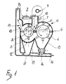
- figure 1 is a schematic view of the various components of the device.
- With reference to the above-cited figure, the device 1 for threshing tobacco leaves 2 for separating the rib and the lamina, is constituted by a first threshing
rotor 3 and by asecond loading rotor 4 rotatably mounted on the casing or framework 11 of the device. Therotors - The
first rotor 3 advantageously but not necessarily has a smaller diameter than that of thesecond rotor 4 and in any case a rotation speed which is considerably greater than the rotation speed of said second rotor. - Indicatively but not necessarily, the
first rotor 3 may rotate at a rate above 400 rpm, whereas thesecond rotor 4 may rotate at a rate which varies between 40 rpm and 80 rpm. - For the sake of clarity, it will be assumed that the
first rotor 3 of figure 1 rotates in a clockwise direction indicated by thearrow 30, and that thesecond rotor 4 rotates in an anticlockwise direction indicated by thearrow 40, though said directions may vary in other embodiments. - The
first rotor 3 is provided with a plurality of first radial blades ordynamic blades 5 which protrude along a plurality of diametrical planes, and comprise a number of blades which may be varied. - The
second rotor 4 also has a plurality of second radial blades 6 which are also arranged along such diametrical planes as to occupy the interspace between two consecutive parallel planes of arrangement of thefirst blades 5. - A number of eight blades at each plane has also been indicated merely by way of example for the
second rotor 4. - The diameter of the first and second rotors as well as the respective speeds and the number of blades are in any case such as to allow a single threshing passage of each of said first blades for each pair of second blades, which occurs at the diametrical plane which is common to both the first and second rotors.
- Thus,
tobacco leaves 2 can be fed into the device 1 at thefeed region 7, which lies above the threshing region and in which said first and second blades are aligned, for example by means of a suitable conveyor 8 arranged above said first and second rotors. - The
leaves 2, fed into the device, become arranged at thefeed region 7, and are forced thereat toward said underlying first and second blades by means of a flow of forced air obtained by means of afan 9 and an appropriatefirst duct 10 which lies above the casing or framework 11 of the device. - The
fan 9 generates a flow of air which conveys theleaves 2 to the threshing region at a speed which is higher than the peripheral speed of thesecond rotor 4, so as to force the deposition of the leaves on the backs of the second blades 6. This avoids effects of rejection and ejection of the leaves on the part of the second rotor and achieves a certain pre-orientation of the leaves on the second blade in a transverse direction. - The use of the
fan 9 to generate an air flow having a greater velocity than the peripheral speed of thesecond rotor 4 does not have the function of mere conveyance of the leaves, but, together with the use of the second rotor, that of forcing the leaves between therear surfaces 41 of blades of said second rotor, thereby achieving a partial pre-orientation of the leaves themselves. - The fact that the first and second rotors are set in phase, for example by means of an appropriate transmission with a reduction ratio, ensures that the leaves undergo just one single threshing operation, thereby causing the resulting lamina and rib to be expelled due to the rotation action of the second rotor and the overlying flow of air. In this manner, useless and harmful further threshing of the leaves is avoided.
- The device may have, below the
first rotor 3, a grid or "basket" 12, and afirst hopper 13 connected to asecond duct 14 which extends laterally to said first rotor. - Similarly, a
second hopper 15 provided with avalve 16 for interconnection with thesecond duct 14 is provided below thesecond rotor 4. - The
first hopper 13 furthermore has afirst tab 17 which protrudes within thesecond duct 14 to create a Venturi effect. - A
rear outlet 18 is provided behind thefirst rotor 3 on the framework 11 on the opposite side with respect to thefirst duct 10 and may also be under negative pressure by virtue of the presence of asecond tab 19 which protrudes into thesecond duct 14 or may exploit the kinetic energy induced in the product by the rotation of the threshing rotor. - Said
outlet 18 allows to extract the strips which, having failed to pass through thebasket 12, would tend to keep rotating, undergoing further useless and harmful threshings at the first and second blades or at other static blades possibly provided. - It has thus been observed that the invention has achieved the intended aim and objects, since the use of the two separate rotors with different speeds and with a different number of blades allows to subject each individual leaf to a single threshing operation which leads to the obtainment of a lamina of considerable size.
- The device furthermore allows to remove, at the
outlet 18 of thefirst rotor 3, the lamina already separated from the rib (also termed "free lamina") without said lamina being subjected to further threshings if it is kept rotating due to failure to pass through thebasket 12. - This, also contributes to the obtainment of laminae with the largest and most uniform possible size for subsequent manufacturing steps.
- The device is furthermore structurally very simple and requires only minimal maintenance, since there are no fixed blades on which laminae may accumulate during threshing. Furthermore, the device is less subject to damage than known devices in the event of accidental introduction of foreign matter.
- The invention is susceptible to numerous modifications and variations, all of which are within the purview of the same inventive concept. For example, any number of blades may constitute the first and second pluralities of blades, and any suitable arrangement of the blades at the peripheral surface of the rotors may be adopted, such as, e.g., a possible arrangement in a spiral or helical configuration may be employed, providing that said blades be arranged periodically mutually in phase at the threshing region defined between the first and second rotors.
- The device may furthermore comprise a plurality of said first and second rotors arranged mutually in sequence, in order to achieve successive further threshings if desired.
- The device may also employ a single threshing rotor with a rear outlet.
- The materials and the dimensions of the individual components of the device may naturally be the most appropriate according to specific requirements.
- Where technical features mentioned in any claim are followed by reference signs, those reference signs have been included for the sole purpose of increasing the intelligibility of the claims and accordingly such reference signs do not have any limiting effect on the scope of each element identified by way of example by such reference signs.
Claims (11)
Applications Claiming Priority (2)
| Application Number | Priority Date | Filing Date | Title |
|---|---|---|---|
| IT8982540A IT1235753B (en) | 1989-05-05 | 1989-05-05 | DEVICE FOR BEATING PARTICULARLY TOBACCO LEAVES |
| IT8254089 | 1989-05-05 |
Publications (2)
| Publication Number | Publication Date |
|---|---|
| EP0398066A1 true EP0398066A1 (en) | 1990-11-22 |
| EP0398066B1 EP0398066B1 (en) | 1996-06-26 |
Family
ID=11318587
Family Applications (1)
| Application Number | Title | Priority Date | Filing Date |
|---|---|---|---|
| EP90108218A Expired - Lifetime EP0398066B1 (en) | 1989-05-05 | 1990-04-30 | Threshing device |
Country Status (11)
| Country | Link |
|---|---|
| US (1) | US5026322A (en) |
| EP (1) | EP0398066B1 (en) |
| AT (1) | ATE139677T1 (en) |
| BR (1) | BR9002095A (en) |
| CA (1) | CA2016093A1 (en) |
| DE (1) | DE69027557T2 (en) |
| ES (1) | ES2088920T3 (en) |
| GR (1) | GR3020697T3 (en) |
| IT (1) | IT1235753B (en) |
| ZA (1) | ZA903077B (en) |
| ZW (1) | ZW6090A1 (en) |
Cited By (1)
| Publication number | Priority date | Publication date | Assignee | Title |
|---|---|---|---|---|
| CN104770854A (en) * | 2015-03-18 | 2015-07-15 | 红塔烟草(集团)有限责任公司 | Equipment for extracting residual leaves from tobacco stems and application method thereof |
Families Citing this family (4)
| Publication number | Priority date | Publication date | Assignee | Title |
|---|---|---|---|---|
| GB0013326D0 (en) | 2000-06-02 | 2000-07-26 | Imp Tobacco Co Ltd | Apparatus and process for threshing tobacco |
| CN103263075B (en) * | 2013-06-11 | 2015-08-12 | 红塔烟草(集团)有限责任公司 | High efficiency energy saving leaf beating wind separating new technology and equipment |
| CN104472119A (en) * | 2014-11-28 | 2015-04-01 | 广西高农机械有限公司 | Auger type seed threshing machine |
| CN113950962A (en) * | 2021-09-06 | 2022-01-21 | 东台市鑫富达机械有限公司 | Continuous and uniform type feeding grain threshing machine |
Citations (5)
| Publication number | Priority date | Publication date | Assignee | Title |
|---|---|---|---|---|
| US2012250A (en) * | 1934-02-08 | 1935-08-20 | American Mach & Foundry | Scrap tobacco cleaning mechanism |
| US2173087A (en) * | 1935-07-31 | 1939-09-19 | Muller J C & Co | Tobacco sorting and separating machine |
| US2789564A (en) * | 1955-01-27 | 1957-04-23 | Brown & Williamson Tobacco | Tobacco leaf deveining machine |
| US3126014A (en) * | 1964-03-24 | Tobacco threshing machine | ||
| US3706314A (en) * | 1970-07-02 | 1972-12-19 | Superior Tobacco Machinery & S | Tobacco threshing apparatus and method |
Family Cites Families (6)
| Publication number | Priority date | Publication date | Assignee | Title |
|---|---|---|---|---|
| US3038476A (en) * | 1958-06-06 | 1962-06-12 | Massey Ferguson Ltd | Series type threshing mechanism |
| US4270551A (en) * | 1979-10-22 | 1981-06-02 | Allis-Chalmers Corporation | Air baffle for harvester accelerator rolls |
| JPS6055113B2 (en) * | 1983-07-21 | 1985-12-03 | 日本たばこ産業株式会社 | Method and device for deboning leaf tobacco, etc. |
| US4627446A (en) * | 1985-03-14 | 1986-12-09 | Deutz-Allis Corporation | Downwardly and rearwardly directed air stream for harvester with vertically offset accelerator rolls |
| JPS6379582A (en) * | 1986-09-24 | 1988-04-09 | 日本たばこ産業株式会社 | Tobacco leaf picking and sorter |
| JPS63219366A (en) * | 1987-03-09 | 1988-09-13 | 日本たばこ産業株式会社 | Apparatus for adjusting gap of slit parts and bone removing machine having said apparatus incorporated therein |
-
1989
- 1989-05-05 IT IT8982540A patent/IT1235753B/en active
-
1990
- 1990-04-24 ZA ZA903077A patent/ZA903077B/en unknown
- 1990-04-24 ZW ZW60/90A patent/ZW6090A1/en unknown
- 1990-04-30 ES ES90108218T patent/ES2088920T3/en not_active Expired - Lifetime
- 1990-04-30 AT AT90108218T patent/ATE139677T1/en active
- 1990-04-30 DE DE69027557T patent/DE69027557T2/en not_active Expired - Fee Related
- 1990-04-30 EP EP90108218A patent/EP0398066B1/en not_active Expired - Lifetime
- 1990-05-01 US US07/517,274 patent/US5026322A/en not_active Expired - Lifetime
- 1990-05-04 CA CA002016093A patent/CA2016093A1/en not_active Abandoned
- 1990-05-04 BR BR909002095A patent/BR9002095A/en unknown
-
1996
- 1996-07-31 GR GR960402064T patent/GR3020697T3/en unknown
Patent Citations (5)
| Publication number | Priority date | Publication date | Assignee | Title |
|---|---|---|---|---|
| US3126014A (en) * | 1964-03-24 | Tobacco threshing machine | ||
| US2012250A (en) * | 1934-02-08 | 1935-08-20 | American Mach & Foundry | Scrap tobacco cleaning mechanism |
| US2173087A (en) * | 1935-07-31 | 1939-09-19 | Muller J C & Co | Tobacco sorting and separating machine |
| US2789564A (en) * | 1955-01-27 | 1957-04-23 | Brown & Williamson Tobacco | Tobacco leaf deveining machine |
| US3706314A (en) * | 1970-07-02 | 1972-12-19 | Superior Tobacco Machinery & S | Tobacco threshing apparatus and method |
Cited By (1)
| Publication number | Priority date | Publication date | Assignee | Title |
|---|---|---|---|---|
| CN104770854A (en) * | 2015-03-18 | 2015-07-15 | 红塔烟草(集团)有限责任公司 | Equipment for extracting residual leaves from tobacco stems and application method thereof |
Also Published As
| Publication number | Publication date |
|---|---|
| BR9002095A (en) | 1991-08-13 |
| DE69027557T2 (en) | 1996-12-12 |
| IT8982540A0 (en) | 1989-05-05 |
| DE69027557D1 (en) | 1996-08-01 |
| GR3020697T3 (en) | 1996-10-31 |
| ZW6090A1 (en) | 1990-10-10 |
| CA2016093A1 (en) | 1990-11-05 |
| IT1235753B (en) | 1992-09-24 |
| EP0398066B1 (en) | 1996-06-26 |
| ES2088920T3 (en) | 1996-10-01 |
| US5026322A (en) | 1991-06-25 |
| ATE139677T1 (en) | 1996-07-15 |
| ZA903077B (en) | 1991-01-30 |
Similar Documents
| Publication | Publication Date | Title |
|---|---|---|
| US3410495A (en) | Wood chipper | |
| US3696817A (en) | Tobacco threshing machine | |
| EP0398066A1 (en) | Threshing device | |
| US5283078A (en) | Process for treating fruits or vegetables with compression stresses | |
| US3384311A (en) | Wood chipper | |
| US2903193A (en) | Grinders | |
| US3126014A (en) | Tobacco threshing machine | |
| CN106072716B (en) | One kind having petiole class defoliating plants device and method | |
| EP0101271A1 (en) | Tobacco opening and conditioning apparatus | |
| US3351000A (en) | Juice extraction apparatus with pulp-peel separator | |
| US3197147A (en) | High speed stress plane material pulverizer | |
| JP3082948B2 (en) | Opening and dedusting equipment for fiber materials, especially cotton | |
| US4195935A (en) | Apparatus for treating materials containing cocoa butter | |
| EP0112040A1 (en) | Tobacco threshing apparatus | |
| CN211388998U (en) | High-efficient novel chinese-medicinal material slicer | |
| US4258728A (en) | Process for improving the fill power of reconstituted tobacco | |
| US2145330A (en) | Threshing apparatus | |
| US4341476A (en) | Apparatus for treating materials containing cocoa butter | |
| US3537494A (en) | Slicing machine | |
| US3590824A (en) | Corn sheller and separator | |
| EP1477074B1 (en) | Method for separating tobacco from a block of tobacco and device for performing the method | |
| US2368800A (en) | Juice extracting apparatus | |
| US3228441A (en) | Stress plane cutter | |
| EP1315426B1 (en) | Rotor blades for food processing machines and related process | |
| CN218534801U (en) | Slicing device suitable for machining of saussurea lappa |
Legal Events
| Date | Code | Title | Description |
|---|---|---|---|
| PUAI | Public reference made under article 153(3) epc to a published international application that has entered the european phase |
Free format text: ORIGINAL CODE: 0009012 |
|
| AK | Designated contracting states |
Kind code of ref document: A1 Designated state(s): AT BE CH DE DK ES FR GB GR IT LI LU NL SE |
|
| 17P | Request for examination filed |
Effective date: 19910419 |
|
| 17Q | First examination report despatched |
Effective date: 19920710 |
|
| GRAH | Despatch of communication of intention to grant a patent |
Free format text: ORIGINAL CODE: EPIDOS IGRA |
|
| GRAA | (expected) grant |
Free format text: ORIGINAL CODE: 0009210 |
|
| AK | Designated contracting states |
Kind code of ref document: B1 Designated state(s): AT BE CH DE DK ES FR GB GR IT LI LU NL SE |
|
| PG25 | Lapsed in a contracting state [announced via postgrant information from national office to epo] |
Ref country code: NL Free format text: LAPSE BECAUSE OF FAILURE TO SUBMIT A TRANSLATION OF THE DESCRIPTION OR TO PAY THE FEE WITHIN THE PRESCRIBED TIME-LIMIT Effective date: 19960626 Ref country code: LI Effective date: 19960626 Ref country code: DK Effective date: 19960626 Ref country code: CH Effective date: 19960626 Ref country code: BE Effective date: 19960626 Ref country code: AT Effective date: 19960626 |
|
| REF | Corresponds to: |
Ref document number: 139677 Country of ref document: AT Date of ref document: 19960715 Kind code of ref document: T |
|
| ET | Fr: translation filed | ||
| REF | Corresponds to: |
Ref document number: 69027557 Country of ref document: DE Date of ref document: 19960801 |
|
| ITF | It: translation for a ep patent filed |
Owner name: MODIANO & ASSOCIATI S.R.L. |
|
| PG25 | Lapsed in a contracting state [announced via postgrant information from national office to epo] |
Ref country code: SE Effective date: 19960926 |
|
| REG | Reference to a national code |
Ref country code: GR Ref legal event code: FG4A Free format text: 3020697 |
|
| REG | Reference to a national code |
Ref country code: ES Ref legal event code: FG2A Ref document number: 2088920 Country of ref document: ES Kind code of ref document: T3 |
|
| REG | Reference to a national code |
Ref country code: ES Ref legal event code: FG2A Ref document number: 2088920 Country of ref document: ES Kind code of ref document: T3 |
|
| NLV1 | Nl: lapsed or annulled due to failure to fulfill the requirements of art. 29p and 29m of the patents act | ||
| REG | Reference to a national code |
Ref country code: CH Ref legal event code: PL |
|
| PG25 | Lapsed in a contracting state [announced via postgrant information from national office to epo] |
Ref country code: LU Free format text: LAPSE BECAUSE OF NON-PAYMENT OF DUE FEES Effective date: 19970430 |
|
| PLBE | No opposition filed within time limit |
Free format text: ORIGINAL CODE: 0009261 |
|
| STAA | Information on the status of an ep patent application or granted ep patent |
Free format text: STATUS: NO OPPOSITION FILED WITHIN TIME LIMIT |
|
| 26N | No opposition filed | ||
| PGFP | Annual fee paid to national office [announced via postgrant information from national office to epo] |
Ref country code: ES Payment date: 19990414 Year of fee payment: 10 |
|
| PGFP | Annual fee paid to national office [announced via postgrant information from national office to epo] |
Ref country code: GR Payment date: 19990416 Year of fee payment: 10 Ref country code: FR Payment date: 19990416 Year of fee payment: 10 |
|
| PGFP | Annual fee paid to national office [announced via postgrant information from national office to epo] |
Ref country code: DE Payment date: 19990419 Year of fee payment: 10 |
|
| PGFP | Annual fee paid to national office [announced via postgrant information from national office to epo] |
Ref country code: GB Payment date: 19990423 Year of fee payment: 10 |
|
| PG25 | Lapsed in a contracting state [announced via postgrant information from national office to epo] |
Ref country code: GR Free format text: LAPSE BECAUSE OF NON-PAYMENT OF DUE FEES Effective date: 20000430 Ref country code: GB Free format text: LAPSE BECAUSE OF NON-PAYMENT OF DUE FEES Effective date: 20000430 |
|
| PG25 | Lapsed in a contracting state [announced via postgrant information from national office to epo] |
Ref country code: ES Free format text: THE PATENT HAS BEEN ANNULLED BY A DECISION OF A NATIONAL AUTHORITY Effective date: 20000503 |
|
| GBPC | Gb: european patent ceased through non-payment of renewal fee |
Effective date: 20000430 |
|
| PG25 | Lapsed in a contracting state [announced via postgrant information from national office to epo] |
Ref country code: FR Free format text: LAPSE BECAUSE OF NON-PAYMENT OF DUE FEES Effective date: 20001229 |
|
| PG25 | Lapsed in a contracting state [announced via postgrant information from national office to epo] |
Ref country code: DE Free format text: LAPSE BECAUSE OF NON-PAYMENT OF DUE FEES Effective date: 20010201 |
|
| REG | Reference to a national code |
Ref country code: FR Ref legal event code: ST |
|
| REG | Reference to a national code |
Ref country code: ES Ref legal event code: FD2A Effective date: 20020204 |
|
| PG25 | Lapsed in a contracting state [announced via postgrant information from national office to epo] |
Ref country code: IT Free format text: LAPSE BECAUSE OF NON-PAYMENT OF DUE FEES;WARNING: LAPSES OF ITALIAN PATENTS WITH EFFECTIVE DATE BEFORE 2007 MAY HAVE OCCURRED AT ANY TIME BEFORE 2007. THE CORRECT EFFECTIVE DATE MAY BE DIFFERENT FROM THE ONE RECORDED. Effective date: 20050430 |