EP0397868B1 - Film-coated sensor - Google Patents
Film-coated sensor Download PDFInfo
- Publication number
- EP0397868B1 EP0397868B1 EP89901741A EP89901741A EP0397868B1 EP 0397868 B1 EP0397868 B1 EP 0397868B1 EP 89901741 A EP89901741 A EP 89901741A EP 89901741 A EP89901741 A EP 89901741A EP 0397868 B1 EP0397868 B1 EP 0397868B1
- Authority
- EP
- European Patent Office
- Prior art keywords
- film
- sensor
- electrode
- oxygen
- coated
- Prior art date
- Legal status (The legal status is an assumption and is not a legal conclusion. Google has not performed a legal analysis and makes no representation as to the accuracy of the status listed.)
- Expired - Lifetime
Links
- 239000000758 substrate Substances 0.000 claims abstract description 16
- 238000000576 coating method Methods 0.000 claims abstract description 10
- 239000011248 coating agent Substances 0.000 claims abstract description 9
- 229920000049 Carbon (fiber) Polymers 0.000 claims description 39
- 239000004917 carbon fiber Substances 0.000 claims description 39
- OKTJSMMVPCPJKN-UHFFFAOYSA-N Carbon Chemical compound [C] OKTJSMMVPCPJKN-UHFFFAOYSA-N 0.000 claims description 16
- 229910052799 carbon Inorganic materials 0.000 claims description 14
- 239000000126 substance Substances 0.000 claims description 11
- 239000003792 electrolyte Substances 0.000 claims description 6
- WABPQHHGFIMREM-UHFFFAOYSA-N lead(0) Chemical compound [Pb] WABPQHHGFIMREM-UHFFFAOYSA-N 0.000 claims description 6
- 239000007787 solid Substances 0.000 claims description 5
- PCHJSUWPFVWCPO-UHFFFAOYSA-N gold Chemical compound [Au] PCHJSUWPFVWCPO-UHFFFAOYSA-N 0.000 claims description 4
- 229910044991 metal oxide Inorganic materials 0.000 claims description 4
- 150000004706 metal oxides Chemical class 0.000 claims description 4
- 239000013060 biological fluid Substances 0.000 claims description 2
- 239000008280 blood Substances 0.000 claims description 2
- 210000004369 blood Anatomy 0.000 claims description 2
- 229910052760 oxygen Inorganic materials 0.000 abstract description 59
- 239000001301 oxygen Substances 0.000 abstract description 59
- QVGXLLKOCUKJST-UHFFFAOYSA-N atomic oxygen Chemical compound [O] QVGXLLKOCUKJST-UHFFFAOYSA-N 0.000 abstract description 56
- 230000004044 response Effects 0.000 abstract description 38
- 238000005259 measurement Methods 0.000 abstract description 21
- 238000006116 polymerization reaction Methods 0.000 abstract description 5
- 108010093096 Immobilized Enzymes Proteins 0.000 abstract 1
- 230000015572 biosynthetic process Effects 0.000 abstract 1
- 238000005243 fluidization Methods 0.000 abstract 1
- 239000007788 liquid Substances 0.000 abstract 1
- 239000010408 film Substances 0.000 description 74
- VNWKTOKETHGBQD-UHFFFAOYSA-N methane Chemical compound C VNWKTOKETHGBQD-UHFFFAOYSA-N 0.000 description 30
- 239000000243 solution Substances 0.000 description 28
- 238000002474 experimental method Methods 0.000 description 16
- 108090000790 Enzymes Proteins 0.000 description 15
- 102000004190 Enzymes Human genes 0.000 description 15
- 238000010586 diagram Methods 0.000 description 15
- 229940088598 enzyme Drugs 0.000 description 15
- BASFCYQUMIYNBI-UHFFFAOYSA-N platinum Chemical compound [Pt] BASFCYQUMIYNBI-UHFFFAOYSA-N 0.000 description 12
- 230000008859 change Effects 0.000 description 9
- 239000007767 bonding agent Substances 0.000 description 8
- MYMOFIZGZYHOMD-UHFFFAOYSA-N Dioxygen Chemical compound O=O MYMOFIZGZYHOMD-UHFFFAOYSA-N 0.000 description 7
- 229910001882 dioxygen Inorganic materials 0.000 description 7
- 238000005868 electrolysis reaction Methods 0.000 description 7
- 239000007888 film coating Substances 0.000 description 7
- 238000009501 film coating Methods 0.000 description 7
- 239000008055 phosphate buffer solution Substances 0.000 description 7
- WQZGKKKJIJFFOK-GASJEMHNSA-N Glucose Natural products OC[C@H]1OC(O)[C@H](O)[C@@H](O)[C@@H]1O WQZGKKKJIJFFOK-GASJEMHNSA-N 0.000 description 6
- 230000003197 catalytic effect Effects 0.000 description 6
- 238000006243 chemical reaction Methods 0.000 description 6
- 230000000052 comparative effect Effects 0.000 description 6
- 239000011521 glass Substances 0.000 description 6
- 239000008103 glucose Substances 0.000 description 6
- 238000000034 method Methods 0.000 description 6
- 229910021607 Silver chloride Inorganic materials 0.000 description 5
- 238000004519 manufacturing process Methods 0.000 description 5
- 229910052697 platinum Inorganic materials 0.000 description 5
- HKZLPVFGJNLROG-UHFFFAOYSA-M silver monochloride Chemical compound [Cl-].[Ag+] HKZLPVFGJNLROG-UHFFFAOYSA-M 0.000 description 5
- 238000002484 cyclic voltammetry Methods 0.000 description 4
- 239000000835 fiber Substances 0.000 description 4
- 239000012528 membrane Substances 0.000 description 4
- -1 polypropylene Polymers 0.000 description 4
- 238000006479 redox reaction Methods 0.000 description 4
- 238000003756 stirring Methods 0.000 description 4
- WEVYAHXRMPXWCK-UHFFFAOYSA-N Acetonitrile Chemical compound CC#N WEVYAHXRMPXWCK-UHFFFAOYSA-N 0.000 description 3
- HSRBHMXIXLWQLL-UHFFFAOYSA-N C12=CC=C(N1)C=C1C=CC(=N1)C=C1C=CC(N1)=CC=1C=CC(N1)=C2.NC2=C(C=CC=C2)[Co] Chemical compound C12=CC=C(N1)C=C1C=CC(=N1)C=C1C=CC(N1)=CC=1C=CC(N1)=C2.NC2=C(C=CC=C2)[Co] HSRBHMXIXLWQLL-UHFFFAOYSA-N 0.000 description 3
- YMWUJEATGCHHMB-UHFFFAOYSA-N Dichloromethane Chemical compound ClCCl YMWUJEATGCHHMB-UHFFFAOYSA-N 0.000 description 3
- BQCADISMDOOEFD-UHFFFAOYSA-N Silver Chemical compound [Ag] BQCADISMDOOEFD-UHFFFAOYSA-N 0.000 description 3
- FAPWRFPIFSIZLT-UHFFFAOYSA-M Sodium chloride Chemical class [Na+].[Cl-] FAPWRFPIFSIZLT-UHFFFAOYSA-M 0.000 description 3
- 229940075397 calomel Drugs 0.000 description 3
- 230000007423 decrease Effects 0.000 description 3
- 238000000151 deposition Methods 0.000 description 3
- ZOMNIUBKTOKEHS-UHFFFAOYSA-L dimercury dichloride Chemical compound Cl[Hg][Hg]Cl ZOMNIUBKTOKEHS-UHFFFAOYSA-L 0.000 description 3
- 239000008151 electrolyte solution Substances 0.000 description 3
- 239000012530 fluid Substances 0.000 description 3
- 239000007789 gas Substances 0.000 description 3
- 239000010439 graphite Substances 0.000 description 3
- 229910002804 graphite Inorganic materials 0.000 description 3
- 239000000463 material Substances 0.000 description 3
- 150000002926 oxygen Chemical class 0.000 description 3
- 229910052709 silver Inorganic materials 0.000 description 3
- 239000004332 silver Substances 0.000 description 3
- SXRSQZLOMIGNAQ-UHFFFAOYSA-N Glutaraldehyde Chemical compound O=CCCCC=O SXRSQZLOMIGNAQ-UHFFFAOYSA-N 0.000 description 2
- DHMQDGOQFOQNFH-UHFFFAOYSA-N Glycine Chemical compound NCC(O)=O DHMQDGOQFOQNFH-UHFFFAOYSA-N 0.000 description 2
- NVJHHSJKESILSZ-UHFFFAOYSA-N [Co].N1C(C=C2N=C(C=C3NC(=C4)C=C3)C=C2)=CC=C1C=C1C=CC4=N1 Chemical compound [Co].N1C(C=C2N=C(C=C3NC(=C4)C=C3)C=C2)=CC=C1C=C1C=CC4=N1 NVJHHSJKESILSZ-UHFFFAOYSA-N 0.000 description 2
- 239000003575 carbonaceous material Substances 0.000 description 2
- 238000010276 construction Methods 0.000 description 2
- 230000008021 deposition Effects 0.000 description 2
- 230000000694 effects Effects 0.000 description 2
- 239000000203 mixture Substances 0.000 description 2
- 230000035484 reaction time Effects 0.000 description 2
- 229920006395 saturated elastomer Polymers 0.000 description 2
- BAZAXWOYCMUHIX-UHFFFAOYSA-M sodium perchlorate Chemical compound [Na+].[O-]Cl(=O)(=O)=O BAZAXWOYCMUHIX-UHFFFAOYSA-M 0.000 description 2
- 229910001488 sodium perchlorate Inorganic materials 0.000 description 2
- 239000010409 thin film Substances 0.000 description 2
- 108091003079 Bovine Serum Albumin Proteins 0.000 description 1
- 239000004593 Epoxy Substances 0.000 description 1
- 108010015776 Glucose oxidase Proteins 0.000 description 1
- 239000004366 Glucose oxidase Substances 0.000 description 1
- 239000004471 Glycine Substances 0.000 description 1
- 239000004743 Polypropylene Substances 0.000 description 1
- 239000004793 Polystyrene Substances 0.000 description 1
- 239000012503 blood component Substances 0.000 description 1
- 229940098773 bovine serum albumin Drugs 0.000 description 1
- 230000005587 bubbling Effects 0.000 description 1
- 239000003054 catalyst Substances 0.000 description 1
- 229920002678 cellulose Polymers 0.000 description 1
- 239000001913 cellulose Substances 0.000 description 1
- 229920002301 cellulose acetate Polymers 0.000 description 1
- 150000001875 compounds Chemical class 0.000 description 1
- 239000004020 conductor Substances 0.000 description 1
- 239000000470 constituent Substances 0.000 description 1
- 238000004132 cross linking Methods 0.000 description 1
- 239000013078 crystal Substances 0.000 description 1
- 125000004122 cyclic group Chemical group 0.000 description 1
- 210000003298 dental enamel Anatomy 0.000 description 1
- HTXDPTMKBJXEOW-UHFFFAOYSA-N dioxoiridium Chemical compound O=[Ir]=O HTXDPTMKBJXEOW-UHFFFAOYSA-N 0.000 description 1
- 238000007598 dipping method Methods 0.000 description 1
- 239000003814 drug Substances 0.000 description 1
- 238000010292 electrical insulation Methods 0.000 description 1
- 238000006911 enzymatic reaction Methods 0.000 description 1
- 235000013305 food Nutrition 0.000 description 1
- 229910021397 glassy carbon Inorganic materials 0.000 description 1
- 229940116332 glucose oxidase Drugs 0.000 description 1
- 235000019420 glucose oxidase Nutrition 0.000 description 1
- 229910052737 gold Inorganic materials 0.000 description 1
- 239000010931 gold Substances 0.000 description 1
- 238000010438 heat treatment Methods 0.000 description 1
- 238000000338 in vitro Methods 0.000 description 1
- RHZWSUVWRRXEJF-UHFFFAOYSA-N indium tin Chemical compound [In].[Sn] RHZWSUVWRRXEJF-UHFFFAOYSA-N 0.000 description 1
- 239000011261 inert gas Substances 0.000 description 1
- 239000012212 insulator Substances 0.000 description 1
- 229910000457 iridium oxide Inorganic materials 0.000 description 1
- 229910052751 metal Inorganic materials 0.000 description 1
- 239000002184 metal Substances 0.000 description 1
- 210000000653 nervous system Anatomy 0.000 description 1
- 229920001155 polypropylene Polymers 0.000 description 1
- 229920002223 polystyrene Polymers 0.000 description 1
- 229920000123 polythiophene Polymers 0.000 description 1
- 229920000915 polyvinyl chloride Polymers 0.000 description 1
- 239000004800 polyvinyl chloride Substances 0.000 description 1
- 238000002360 preparation method Methods 0.000 description 1
- 230000008569 process Effects 0.000 description 1
- 102000004169 proteins and genes Human genes 0.000 description 1
- 108090000623 proteins and genes Proteins 0.000 description 1
- 230000010349 pulsation Effects 0.000 description 1
- 230000009467 reduction Effects 0.000 description 1
- 229910052702 rhenium Inorganic materials 0.000 description 1
- HYERJXDYFLQTGF-UHFFFAOYSA-N rhenium Chemical compound [Re][Re][Re][Re][Re][Re][Re][Re][Re][Re][Re][Re][Re][Re][Re][Re][Re][Re][Re][Re][Re][Re][Re][Re][Re][Re][Re][Re][Re][Re][Re][Re][Re][Re][Re][Re][Re][Re][Re][Re][Re][Re][Re][Re][Re][Re][Re][Re][Re][Re][Re][Re][Re][Re][Re][Re][Re][Re][Re][Re][Re][Re][Re][Re][Re][Re][Re][Re] HYERJXDYFLQTGF-UHFFFAOYSA-N 0.000 description 1
- 238000010408 sweeping Methods 0.000 description 1
- 229910001887 tin oxide Inorganic materials 0.000 description 1
- 238000001075 voltammogram Methods 0.000 description 1
- 238000005406 washing Methods 0.000 description 1
Images






Classifications
-
- A—HUMAN NECESSITIES
- A61—MEDICAL OR VETERINARY SCIENCE; HYGIENE
- A61B—DIAGNOSIS; SURGERY; IDENTIFICATION
- A61B5/00—Measuring for diagnostic purposes; Identification of persons
- A61B5/145—Measuring characteristics of blood in vivo, e.g. gas concentration or pH-value ; Measuring characteristics of body fluids or tissues, e.g. interstitial fluid or cerebral tissue
- A61B5/14542—Measuring characteristics of blood in vivo, e.g. gas concentration or pH-value ; Measuring characteristics of body fluids or tissues, e.g. interstitial fluid or cerebral tissue for measuring blood gases
-
- A—HUMAN NECESSITIES
- A61—MEDICAL OR VETERINARY SCIENCE; HYGIENE
- A61B—DIAGNOSIS; SURGERY; IDENTIFICATION
- A61B5/00—Measuring for diagnostic purposes; Identification of persons
- A61B5/145—Measuring characteristics of blood in vivo, e.g. gas concentration or pH-value ; Measuring characteristics of body fluids or tissues, e.g. interstitial fluid or cerebral tissue
- A61B5/1468—Measuring characteristics of blood in vivo, e.g. gas concentration or pH-value ; Measuring characteristics of body fluids or tissues, e.g. interstitial fluid or cerebral tissue using chemical or electrochemical methods, e.g. by polarographic means
- A61B5/1486—Measuring characteristics of blood in vivo, e.g. gas concentration or pH-value ; Measuring characteristics of body fluids or tissues, e.g. interstitial fluid or cerebral tissue using chemical or electrochemical methods, e.g. by polarographic means using enzyme electrodes, e.g. with immobilised oxidase
- A61B5/14865—Measuring characteristics of blood in vivo, e.g. gas concentration or pH-value ; Measuring characteristics of body fluids or tissues, e.g. interstitial fluid or cerebral tissue using chemical or electrochemical methods, e.g. by polarographic means using enzyme electrodes, e.g. with immobilised oxidase invasive, e.g. introduced into the body by a catheter or needle or using implanted sensors
-
- A—HUMAN NECESSITIES
- A61—MEDICAL OR VETERINARY SCIENCE; HYGIENE
- A61B—DIAGNOSIS; SURGERY; IDENTIFICATION
- A61B2562/00—Details of sensors; Constructional details of sensor housings or probes; Accessories for sensors
- A61B2562/02—Details of sensors specially adapted for in-vivo measurements
Definitions
- This invention relates to a film-coated sensor and, more particularly, to a solid-film-type, miniature film-coated sensor used upon being inserted into a living body.
- a solid-film-type film-coated sensor has long been desired in the fields of medicine and foods.
- Film-coated sensors of the coated wire electrode-type in which a platinum electrode is directly coated with a polymeric film (e.g., a cellulose film), have recently appeared on the market. Examples of such sensors are disclosed in US patent 3 476 670, JP-A-61/33 644 and EP-A2-235 016. However, these sensors exhibit problems in terms of durability.
- the rate at which oxygen in a specimen solution reaches an internal response electrode is limited.
- the film thickness of a gas-permeable membrane is reduced and the area of the responsive portion of the sensor is increased, the sensor is readily influenced by flow of the specimen solution, and this is a cause of drift.
- the form of the sensor be such that the area having the oxygen-reducing function be very small (on the order of square microns).
- the oxygen sensor be one in which coexisting substances are excluded and only the oxygen is acted upon by the oxygen-reducing reaction efficiently by way of an oxygen-reducing membrane. It is especially desired that the sensor have a very small area also from the standpoint of excluding the coexisting substances.
- An object of the present invention is to solve the foregoing problems of the prior art and provide a miniature film-coated sensor in which the surface is uniform, the film coating is readily controlled and there is little drift because the sensor is not readily influenced by the flow of the specimen solution.
- a further object of the invention is to provide a film-coated sensor which has a quick response and which is not readily influenced by electrode-activated substances other than substances to be measured that are present in solution.
- an object of the invantion is to provide a film-coated sensor having a quick response of less than 10 seconds.
- a film-coated sensor capable of measuring trace amounts (less than 10 »l) of a sample and of performing measurement upon being directly inserted into a living body or tissue.
- a film-coated sensor is a film-coated sensor comprising : a capillary ; an electrically conductive substrate, composed of carbon fibers, a carbon rod-shaped member, gold wire or a metal oxide, which is connected to a lead wire at one end of said capillary and inscribed in said capillary, the sectional area of said electrically conductive substrate being less than 10 ⁇ 9 m2; and a solid coating film which coats, to a predetermined depth, an end face of said electrically conductive substrate at another end, which is open, of said capillary.
- the electrically conductive substrate is composed of carbon fibers, a carbon rod-shaped member, gold wire or a metal oxide.
- the sectional area of the electrically conductive substrate is less than 10 ⁇ 9 m2.
- the solid coating film may be a film which responds only to a gas or electrolyte from an activated substance of interest contained in blood or a related biological fluid.
- a miniature film-coated sensor in which the surface is uniform, the film coating is readily controlled and there is little drift because the sensor is not readily influenced by the flow of the specimen solution.
- a film-coated sensor which has a quick response and which is not readily influenced by electrode-activated substances other than substances to be measured that are present in solution.
- a film-coated sensor having a quick response of less than 10 seconds.
- a film-coated sensor capable of measuring trace amounts (less than 10 »l) of a sample and of performing measurement upon being directly inserted into a living body or tissue. Furthermore, the film-coated sensor of the present invention is capable of being mass-produced since the sensor characteristics are uniform.
- the electrode area will be ultraminiaturized.
- a film-coated sensor is typified by an oxygen sensor and an enzyme sensor employing the oxygen sensor.
- the present invention is applied similarly to other film-coated sensors as well.
- the oxygen sensors of these embodiments are miniature oxygen sensors in which the rod-shaped cross section of a carbon material including carbon fiber material is made less than 10 ⁇ 9 m2 and is directly coated with an oxygen gas-responsive reducing film.
- the sectional area of the responsive portion is less than 1 x 10 ⁇ 9 m2 (which corresponds to 3 - 4 carbon fibers, where the diameter of one carbon fiber is 6 »m), preferably 2.83 x 10 ⁇ 11 m2 (which corresponds to one carbon fiber).
- Electrically conductive carbon is ideal as an electrically conductive substrate. Examples which can be mentioned are basal plane pyrolytic graphite, glassy carbon and the like. Among these, electrically conductive carbon having a graphite crystal structure is especially preferred.
- Two capillaries 1 of a shape comprising a main-body portion 1b and a capillary tube portion la shown in Fig. 1A were fabricated by extending glass tubes having an outer diameter of 3 mm and a length of 5 cm using a miniature electrode manufacturing apparatus.
- a carbon fiber 2 (Besfighte®, manufactured by Toho Rayon) was inserted into the capillary tube portion 1a (the extended portion) of one of the capillaries 1, and the gap between the capillary tube and the carbon fiber was filled with electron wax 3 (manufactured by So Denshi Kogyo) serving as an insulative bonding agent, thereby insulating the carbon fiber.
- Silver paste 4 serving as an electrically conductive bonding agent was injected from the other end, a lead wire 5 was inserted from this end to achieve an electrical connection, and this end was sealed and the lead wire 5 fixed by an insulative bonding agent 6 in such a manner as to prevent leakage of the silver paste 4. Further, the tip of the capillary tube portion was polished (0.5 »m sandpaper, PR1-24, manufactured by 3M Company). A carbon-fiber electrode 10 was thus completed.
- FIG. 1B A schematic view of the carbon-fiber electrode 10 is shown in Fig. 1B.
- a glass tube is used as the capillary 1, although the invention is not limited to a glass tube so long as an insulative capillary tube is obtained by heating or drawing.
- Materials which can be used are polyvinyl chloride, polypropylene, polystyrene, etc.
- the surface of the carbon fiber 2 of the above-described carbon-fiber electrode 10 was coated with an electrolytic polymeric film 7 made of meso-tetra (o-aminophenyl) cobalt porphyrin (abbreviated to Co-TAPP).
- the electrolytic polymeric film 7 was deposited by performing electrolysis for 60 seconds at a constant potential of +1.8 volts (vs. Ag/AgCl) in an electrolyte having the following composition:
- the current change of constant-potential electrolysis at this time is shown in Fig. 2.
- the time for convergence to a constant current is about 60 seconds.
- the current value becomes constant in 40 seconds in case of two carbon fibers (sectional area: 5.652 x 10 ⁇ 11 m2) and in 20 seconds in case of five carbon fibers (sectional area: 1.413 x 10 ⁇ 10 m2).
- a thin film is formed in this sequence and film deposition control is shortened.
- FIG. 1C A schematic view of the oxygen sensor thus manufactured is illustrated in Fig. 1C.
- the redox current value becomes approximately constant in Fig. 3A
- the redox current value varies with a change in potential value when the sectional area of the carbon fibers is 1.413 x 10 ⁇ 10 m2 (a bundle of five or more carbon fibers). Accordingly, when it is attempted to obtain a constant current value, the sectional area of the carbon electrode should be less than about 10 ⁇ 9 m2, and an ideal sectional area is 2.83 x 10 ⁇ 11 m2 (which corresponds to one carbon fiber).
- electrode area should be between 2.826 x 10 ⁇ 11 m2 (one carbon fiber) and 2.826 x 10 ⁇ 10 m2 (ten carbon fibers).
- the value of 2.826 x 10 ⁇ 11 m2 (one carbon fiber) is preferred, as drift becomes small at this value. This is deemed to be best for attaining the present object.
- the oxygen sensor of the present embodiment has the following advantages:
- the surface concentration of the electrolytic polymeric film was measured with respect to electrode area when the area of the responsive portion of the electrode was made 7.85 x 10 ⁇ 11 m2, 7.85 x 10 ⁇ 10 m2 and 7.85 x 10 ⁇ 9 m2.
- the surface concentration of the Co-TAPP increases as electrode area increases at areas greater than 7.85 x 10 ⁇ 10 m2. However, there is almost no change at areas less than 7.85 x 10 ⁇ 10 m2. This facilitates uniformalization of sensor characteristics and make possible mass production of the film-coated sensor.
- Measurement was performed at an oxygen concentration of 0 Pa (bubbling in N2) in an electrolytic solution (a phosphate buffer solution having a pH of 7.4) at room temperature.
- the senor is fabricated by integrating the main portion 1b and the capillary portion 1a.
- the sensor can be fabricated by coating and insulating the carbon fiber, with the exception of both ends thereof, with an insulator such as a polyethylene fluoride tube or enamel, coating one end with the electrolytic polymeric film 7, connecting the other end to the lead wire via the electrically conductive bonding agent 6, thereby forming the main-body portion 1b and the capillary portion 1a separately, and then uniting these two portions.
- the film-coated sensor of the embodiment described next is an ultraminiature oxygen sensor in which one filament of a carbon fiber is adopted as an electrically conductive substrate the surface whereof is coated with a cobalt-porphyrin polymeric film, which possesses an oxygen-reducing catalytic function, using an electrolytic polymerization process. It is possible to make the outer diameter of the sensor tip 10 to 50 »m to measure a very small sample on the microliter order or to measure oxygen concentration in cells or the nervous system, etc. Since a carbon fiber of less than 10 »m is used as the electrically conductive substrate, speed of response is very high and it is possible to measure oxygen concentration within one second at 90% response. In addition, there is almost no influence from pulsation.
- the film thickness of the Co-TAPP film 16 in this case was 0.5 »m.
- a film thickness of 400 A - 50 »m is preferred, particularly a film thickness of 1 - 10 »m. Sensor characteristics are unsatisfactory below 400 ⁇ , and peeling of the film easily occurs above 50 »m.
- the oxygen sensor fabricated in Embodiment 2 and an Ag/AgCl electrode available on the market were immersed in a 50 mmol/l phosphate buffer solution (pH: 7.4), a potential of -0.6 V with respect to the Ag/AgCl electrode was applied to the sensor, and the value of current flow was measured while changing the O2 concentration of the gas passes through the solution.
- the results are plotted in Fig. 7A.
- a voltage of -0.6 V was decided from the result of measurement current vs. voltage shown in Fig. 7B.
- an oxygen sensor having a large area was fabricated by coating the surface of the electrode with a Co-TAPP film (film thickness: 0.5 »m) using a method similar to that of Embodiment 2.
- Oxygen sensors created in accordance with Embodiment 2 and Comparative Example 1 were immersed in a phosphate buffer solution along with a reference electrode, current value when a potential of -0.6 V was applied to the reference electrode and the solution was stirred was compared with a case in which the solution was not stirred, and susceptibility to the influence of fluid flow was evaluated. The results are shown in Figs. 10A and 10B.
- current value does not change regardless of whether the solution is or is not stirred, as shown in Fig. 10A.
- Fig. 10B With the sensor of Comparative Example 1, however, as shown in Fig. 10B, it was found that while current fluctuates when stirring is performed, fluctuation ceases when stirring is stopped but the current value decreases at such time. On the basis of these results, it was confirmed that the sensor fabricated in accordance with Embodiment 2 is capable of accurate measurement without being influenced by flow of the fluid.
- an oxygen sensor having a quick 90% response of less than one second is obtained by using an electrode having a very small area, namely the cross section of a carbon fiber, and coating this electrode with a film having an oxygen-reducing function.
- the oxygen sensor is capable of measuring oxygen concentration without being influenced by other coexisting chemical substances and without being influenced by fluid flow.
- the electrode portion is extremely small, measurement is possible with a minute amount of a sample or at a very small region.
- an ultraminiature enzyme sensor is provided by achieving miniaturization using one filament of a carbon fiber and forming a thin film on a minute portion using electrolytic polymerization.
- the purpose is to realize miniaturization and high-speed response and measure substrate concentration in vitro (in tissue) or in a minute amount of a sample.
- a sensor is provided in which speed of response is less than three seconds for 95% response and the outer diameter of the sensor tip is less than 100 »m (where the responsive portion is less than 10 »m).
- Examples of chemical compounds which take part in enzyme reactions and are produced or consumed and exhibit electrode activity are 02, H2O2, CO2, etc.
- a cobalt porphyrin polymeric film is preferred as an O2-reducing catalytic film, a poly(4,4′-biphenol) film as an H2O2-oxidizing catalytic film, and a film comprising polythiophene film/silver/rhenium as a CO2-reducing catalyst.
- An electrolytic polymerization process is preferred as the coating process for applying these films.
- FIG. 11 A schematic view showing the construction of an ultraminiature enzyme sensor according to this embodiment is illustrated in Fig. 11. Reference numerals identical with those in Fig. 6 designate the same constituent substances.
- One end of the carbon fiber 11 is connected to the lead wire 12 using the electrically conductive bonding agent 13, the tip of the carbon fiber is inserted into the finely extended glass capillary 14, and the capillary is subsequently filled with the insulative bonding agent 15 to achieve electrical insulation.
- a portion of the tip of this capillary electrode is cut off and the cut tip is polished to fabricate a carbon-disk electrode for an ultraminiature enzyme sensor.
- the electrode thus manufactured catalyzes the electrolytic reducing reaction of oxygen in solution.
- the oxygen reducing reaction occurs at a potential of -500 to -600 mV, and a steady current is obtained even at a sweep speed of 50 mV/sec.
- the surface of the electrolytic polymeric film (the oxygen-reducing catalytic film) was coated with an enzyme-fixing film 17 by a method described below.
- An oxygen-reducing catalytic-film electrode was immersed five times in a solution obtained by dissolving 100 mg/ml of glucose oxidase and 15 weight-% of bovine serum albumin in a pH 8.0 phosphate buffer solution. After the electrode was allowed to dry, a cross-linking reaction was allowed to take place for 12 hours in a glutaric aldehyde vapor of a 50% glutaric aldehyde solution. This was followed by washing with a 20% glycine solution.
- a glucose oxidase-fixing film was formed (film thickness: 10 »m) to fabricate an ultraminiature enzyme sensor.
- Constant-potential electrolysis at -0.6 V vs. SSCE was performed with a three-electrode cell using the subminiature enzyme sensor of Embodiment 4 (carbon-fiber cross section: 7.85 x 10 ⁇ 11 m2) as an sectional area electrode, a saturated sodium chloride calomel electrode (SSCE) as a reference electrode and a platinum wire as an opposing electrode.
- a plot of current response at this time with respect to glucose concentration in the solution is shown in Fig. 13.
- a region of linear current response was obtained over a range of glucose concentration of 0 - 105 mg/dl. It was found that response time in this case is less than two seconds for a 95% response, which is indicative of a very high speed of response.
- the specimen solution was stirred gently with a stirrer at 25°C and measured using a 5 mM phosphate buffer solution (pH: 6.2).
- a glucose-permeable film 18 (20 »m) was formed by repeatedly dipping the sensor in a dichloromethane solution of 5% cellulose acetate, and allowing it to dry, three times.
- the enzyme-fixed film preferably is 400 ⁇ - 50 »m, with 1 - 10 »m being particularly desirable.
- the enzyme is not fixed sufficiently and lifetime is short below 400 ⁇ , and speed of response diminishes when 100 »m is exceeded.
- the subminiature enzyme sensor of Embodiment 5 was treated as in Experiment 9 and current response with respect to glucose concentration was investigated. As a result, it was found that the region of linear current covered a wide range of 0 - 240 mg/dl. It was found that speed of response in this case was less than three seconds for a 95% response, and that a slowing of the response due to the glucose-permeable film was small.
- the electrode area is ultraminiaturized in the enzyme sensor of the present embodiment.
- material other than a slender carbon material such as a metal (e.g., gold) or metal oxide [iridium oxide, indium tin oxide (ITO)], may be used as the electrically conductive substrate.
- a metal e.g., gold
- metal oxide iridium oxide, indium tin oxide (ITO)
- film-coated sensors of these embodiments are typified by oxygen sensors and enzyme sensors, as stated at the beginning of the description of the embodiments, the present invention can be similarly applied to other film-coated sensors.
Landscapes
- Life Sciences & Earth Sciences (AREA)
- Health & Medical Sciences (AREA)
- Physics & Mathematics (AREA)
- Biomedical Technology (AREA)
- Medical Informatics (AREA)
- Veterinary Medicine (AREA)
- Public Health (AREA)
- Biophysics (AREA)
- Pathology (AREA)
- Engineering & Computer Science (AREA)
- General Health & Medical Sciences (AREA)
- Heart & Thoracic Surgery (AREA)
- Optics & Photonics (AREA)
- Molecular Biology (AREA)
- Surgery (AREA)
- Animal Behavior & Ethology (AREA)
- Chemical & Material Sciences (AREA)
- Chemical Kinetics & Catalysis (AREA)
- General Chemical & Material Sciences (AREA)
- Measurement Of The Respiration, Hearing Ability, Form, And Blood Characteristics Of Living Organisms (AREA)
Abstract
Description
- This invention relates to a film-coated sensor and, more particularly, to a solid-film-type, miniature film-coated sensor used upon being inserted into a living body.
- A solid-film-type film-coated sensor has long been desired in the fields of medicine and foods. Film-coated sensors of the coated wire electrode-type, in which a platinum electrode is directly coated with a polymeric film (e.g., a cellulose film), have recently appeared on the market. Examples of such sensors are disclosed in US
patent 3 476 670, JP-A-61/33 644 and EP-A2-235 016. However, these sensors exhibit problems in terms of durability. - For example, in a solid-film-type oxygen sensor, the rate at which oxygen in a specimen solution reaches an internal response electrode is limited. Though this problem can be solved if the film thickness of a gas-permeable membrane is reduced and the area of the responsive portion of the sensor is increased, the sensor is readily influenced by flow of the specimen solution, and this is a cause of drift. Accordingly, in a case where a small amount (on the order of 1 »l) of a specimen solution is to be measured, it is preferred that the form of the sensor be such that the area having the oxygen-reducing function be very small (on the order of square microns). In particular, in a case where a miniature sensor is directly inserted into a living body to continuously measure the partial pressure of oxygen in a solution containing a substance to be reduced, it is preferred that the oxygen sensor be one in which coexisting substances are excluded and only the oxygen is acted upon by the oxygen-reducing reaction efficiently by way of an oxygen-reducing membrane. It is especially desired that the sensor have a very small area also from the standpoint of excluding the coexisting substances.
- With an oxygen sensor in which the gas-permeable membrane is further coated with an enzyme-fixing membrane, time is required for the permeation of oxygen gas and response time (a 90% response) takes more than one minute.
- Thus, there is increasing demand for a quick-response, miniaturized film-coated sensor in which a solid film coating is readily controlled, and in which there is little drift.
- Furthermore, when measurement is performed in a blood component, accurate measurement is made impossible owing to adhesion of protein to the surface of a platinum electrode.
- An object of the present invention is to solve the foregoing problems of the prior art and provide a miniature film-coated sensor in which the surface is uniform, the film coating is readily controlled and there is little drift because the sensor is not readily influenced by the flow of the specimen solution.
- A further object of the invention is to provide a film-coated sensor which has a quick response and which is not readily influenced by electrode-activated substances other than substances to be measured that are present in solution. In particular, an object of the invantion is to provide a film-coated sensor having a quick response of less than 10 seconds.
- Thus, there is provided a film-coated sensor capable of measuring trace amounts (less than 10 »l) of a sample and of performing measurement upon being directly inserted into a living body or tissue.
- In order to attain the foregoing objects, a film-coated sensor according to the present invention is a film-coated sensor comprising :
a capillary ;
an electrically conductive substrate, composed of carbon fibers, a carbon rod-shaped member, gold wire or a metal oxide, which is connected to a lead wire at one end of said capillary and inscribed in said capillary, the sectional area of said electrically conductive substrate being less than 10⁻⁹ m²; and
a solid coating film which coats, to a predetermined depth, an end face of said electrically conductive substrate at another end, which is open, of said capillary. - The electrically conductive substrate is composed of carbon fibers, a carbon rod-shaped member, gold wire or a metal oxide.
- The sectional area of the electrically conductive substrate is less than 10⁻⁹ m².
- Further the solid coating film may be a film which responds only to a gas or electrolyte from an activated substance of interest contained in blood or a related biological fluid.
- According to the present invention, there can be provided a miniature film-coated sensor in which the surface is uniform, the film coating is readily controlled and there is little drift because the sensor is not readily influenced by the flow of the specimen solution.
- Further, there can be provided a film-coated sensor which has a quick response and which is not readily influenced by electrode-activated substances other than substances to be measured that are present in solution. In particular, there can be provided a film-coated sensor having a quick response of less than 10 seconds.
- Thus, there is provided a film-coated sensor capable of measuring trace amounts (less than 10 »l) of a sample and of performing measurement upon being directly inserted into a living body or tissue. Furthermore, the film-coated sensor of the present invention is capable of being mass-produced since the sensor characteristics are uniform.
- More particularly, in a case where the present invention is applied to an oxygen sensor, the following advantages are obtained:
- (i) As for the electrochemical behavior (the redox reaction response) of Fe(CN)₆³⁻, Fe(CN)₆⁴⁻ of a carbon electrode, the redox wave is symmetrical and the current value is substantially constant, irrespective of electrode surface area, when the sectional area of the responsive portion of the electrode is less than 10⁻⁹ m², preferably 2.83 x 10⁻¹¹ m².
- (ii) Drift is almost non-existent as a result of using a film-coated oxygen electrode in which a carbon electrode base is directly coated with an oxygen gas-responsive reducing film.
- (iii) Though the residual current value calculated from oxygen partial pressure vs. current density increases as the area of the electrode base decreases, the residual current is constant, on the order of 1 (A/m²), for a sectional area of less than 10⁻⁹ m².
- (iv) As for the electrolytic conditions of the film coating when the carbon electrode is coated with the oxygen gas-responsive reducing film, control of electrolytic reaction time is limited to a very short time of less than 10 seconds, by way of example, if the sectional area of the responsive portion of the electrode is greater than 10⁻⁹ m². However, if this sectional area is less than 10⁻⁹ m², control of the electrolytic film coating is possible over an extended time period of more than 60 seconds (more than one minute).
- If the invention is applied to an enzyme sensor, on the other hand, the electrode area will be ultraminiaturized. The following advantages are obtained as a result:
- (1) Basic concentration measurement in a living body or tissue is possible.
- (2) Measurement of trace amounts of a sample on the »l order is of course possible.
- (3) Since the sensor substrate is ultraminiaturized, response is a very quick three seconds and rapid measurement is possible.
- (4) Cost is low since inexpensive carbon fiber can be used.
- (5) A change in concentration caused by reaction is negligible owing to the very small responsive area.
- (6) The influence of solution fluidity and flow is negligible.
- Other objects and effects will become apparent from a description of embodiments with reference to the following drawings.
-
- Fig. 1A is a diagram illustrating a glass capillary of
Embodiment 1; - Fig. 1B is a diagram illustrating the structure of a carbon-fiber electrode of
Embodiment 1; - Fig. 1C is a diagram illustrating the structure of an oxygen sensor of
Embodiment 1; - Fig. 2 is a diagram illustrating a current change in constant-current electrolysis during preparation of an electrolytic polymeric film;
- Figs. 3A through 3C are diagrams showing cyclic voltammograms of redox reactions of a miniature carbon-fiber electrode of
Embodiment 1; - Fig. 4 is a diagram in which the relationship between current density and partial pressure of oxygen of an oxygen sensor according to
Embodiment 1 is plotted in a case where the area of the responsive portion of the electrode is varied; - Fig. 5A is a diagram showing electrode drift due to the influence of flow in the oxygen sensor of
Embodiment 1; - Fig. 5B is a diagram showing the surface concentration and electrode area of the oxygen sensor of
Embodiment 1; - Fig. 5C is a diagram showing the relationship between peak current density and potential sweep velocity of the oxygen sensor of
Embodiment 1; - Fig. 6 is a schematic view showing the structure of an oxygen sensor fabricated according to
Embodiment 2; - Figs. 7A and 7B are diagrams showing the response of the oxygen sensor fabricated according to
Embodiment 2; - Fig. 8 is a diagram showing the response rate of the oxygen sensor fabricated according to
Embodiment 2; - Fig. 9 is a diagram showing the response rate of an oxygen sensor fabricated according to Comparative Example 1;
- Figs. 10A and 10B are diagrams showing the influence of flow in the oxygen sensors fabricated according to
Embodiment 2 and Comparative Example 1; - Fig. 11 is a schematic view representing the construction of enzyme sensors of
Embodiments - Fig. 12 is a diagram representing cyclic voltammetric response with respect to enzyme reduction of an electrode coated with an enzyme-reducing catalytic film of
Embodiment 3; and - Fig. 13 is a diagram showing current response with respect to a change in glucose concentration of a glucose sensor of
Embodiments - Embodiments of the present invention will now be described while referring to the accompanying drawings. In these embodiments, a film-coated sensor is typified by an oxygen sensor and an enzyme sensor employing the oxygen sensor. However, the present invention is applied similarly to other film-coated sensors as well.
- The oxygen sensors of these embodiments are miniature oxygen sensors in which the rod-shaped cross section of a carbon material including carbon fiber material is made less than 10⁻⁹ m² and is directly coated with an oxygen gas-responsive reducing film. According to these embodiments, the sectional area of the responsive portion is less than 1 x 10⁻⁹ m² (which corresponds to 3 - 4 carbon fibers, where the diameter of one carbon fiber is 6 »m), preferably 2.83 x 10⁻¹¹ m² (which corresponds to one carbon fiber).
- Electrically conductive carbon is ideal as an electrically conductive substrate. Examples which can be mentioned are basal plane pyrolytic graphite, glassy carbon and the like. Among these, electrically conductive carbon having a graphite crystal structure is especially preferred.
- Two
capillaries 1 of a shape comprising a main-body portion 1b and a capillary tube portion la shown in Fig. 1A were fabricated by extending glass tubes having an outer diameter of 3 mm and a length of 5 cm using a miniature electrode manufacturing apparatus. A carbon fiber 2 (Besfighte®, manufactured by Toho Rayon) was inserted into thecapillary tube portion 1a (the extended portion) of one of thecapillaries 1, and the gap between the capillary tube and the carbon fiber was filled with electron wax 3 (manufactured by So Denshi Kogyo) serving as an insulative bonding agent, thereby insulating the carbon fiber.Silver paste 4 serving as an electrically conductive bonding agent was injected from the other end, alead wire 5 was inserted from this end to achieve an electrical connection, and this end was sealed and thelead wire 5 fixed by aninsulative bonding agent 6 in such a manner as to prevent leakage of thesilver paste 4. Further, the tip of the capillary tube portion was polished (0.5 »m sandpaper, PR1-24, manufactured by 3M Company). A carbon-fiber electrode 10 was thus completed. - A schematic view of the carbon-
fiber electrode 10 is shown in Fig. 1B. Here a glass tube is used as thecapillary 1, although the invention is not limited to a glass tube so long as an insulative capillary tube is obtained by heating or drawing. Materials which can be used are polyvinyl chloride, polypropylene, polystyrene, etc. - By employing a method illustrated below, the surface of the
carbon fiber 2 of the above-described carbon-fiber electrode 10 was coated with anelectrolytic polymeric film 7 made of meso-tetra (o-aminophenyl) cobalt porphyrin (abbreviated to Co-TAPP). - By using a three-electrode cell having the carbon-
fiber electrode 10 as an active electrode, an Ag/AgCl electrode available on the market as a reference electrode and a platinum coil as an opposing electrode, theelectrolytic polymeric film 7 was deposited by performing electrolysis for 60 seconds at a constant potential of +1.8 volts (vs. Ag/AgCl) in an electrolyte having the following composition:
- The current change of constant-potential electrolysis at this time is shown in Fig. 2. The time for convergence to a constant current is about 60 seconds. For purposes of comparison, the current value becomes constant in 40 seconds in case of two carbon fibers (sectional area: 5.652 x 10⁻¹¹ m²) and in 20 seconds in case of five carbon fibers (sectional area: 1.413 x 10⁻¹⁰ m²). A thin film is formed in this sequence and film deposition control is shortened.
- A schematic view of the oxygen sensor thus manufactured is illustrated in Fig. 1C.
- By employing an electrode cell using the miniature carbon-fiber electrode shown in Fig. 1B of
Embodiment 1 as an active electrode, a saturated sodium chloride calomel electrode as a reference electrode and a platinum mesh as an opposing electrode, measurement of the cyclic voltammetry of a redox reaction of Fe(CN)₆³⁻ and Fe(CN)₆⁴⁻ on the surface of a miniature oxygen electrode was measured in the following electrolyte:
20 mM Fe(CN)₆³⁻
0.1 M NaClO₄ - The results are shown in Fig. 3(a). Cyclic voltammograms for carbon-fiber sectional areas of 1.413 x 10⁻¹⁰ m² (a five-fiber bundle) and 2.826 x 10⁻⁹ m² (a 100-fiber bundle) are shown in Figs. 3B and 3C for purposes of comparison.
- As a result, it was confirmed that while the redox current value becomes approximately constant in Fig. 3A, the redox current value varies with a change in potential value when the sectional area of the carbon fibers is 1.413 x 10⁻¹⁰ m² (a bundle of five or more carbon fibers). Accordingly, when it is attempted to obtain a constant current value, the sectional area of the carbon electrode should be less than about 10⁻⁹ m², and an ideal sectional area is 2.83 x 10⁻¹¹ m² (which corresponds to one carbon fiber).
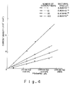
- The relationship between current density (A/m²) and partial pressure of oxygen (mmHg) when the area of the responsive portion of the electrode is varied from 2.826 x 10⁻¹¹ m² to 2.826 x 10⁻⁹ m² is illustrated in Table 1 and in Fig. 4, in which this relationship is plotted. The oxygen sensor used was that fabricated in
Embodiment 1. Measurement was performed at different partial pressures of oxygen of 20, 60, 85 and 128 mmHg using N₂ gas as an inert gas. When residual current is obtained from the relationship between current density and the pO₂ partial pressure, the result is the residual-current column of Table 1.
- As a result, when the area of the responsive portion of the electrode is less than 8.478 x 10⁻⁶ cm2 (a bundle of five fibers), residual current converges to a value between 1.484 A/m² and 1.770 A/m².
- By using the oxygen sensor of the embodiment in the same manner as
Experiment 2, electrode drift (a variance in current density) due to the influence of flow of the specimen solution was examined in an electrolyte solution (a phosphate buffer solution having a pH of 7.4) under constant conditions where the oxygen concentration was 140 mmHg and temperature was adjusted to 37 ± 0.05°C. The results are shown in Fig. 5A, where the stirring speed of a stirrer for stirring the specimen solution was varied and flow rate was changed over between 250 ml/min and 1200 ml/min. - The Figure shows that drift tends to increase as electrode area increases in the manner 2.826 x 10⁻¹¹ m², 2.826 x 10⁻¹⁰ m², 8.478 x 10⁻¹⁰ m² and 2.826 x 10⁻⁹ m². Accordingly, electrode area should be between 2.826 x 10⁻¹¹ m² (one carbon fiber) and 2.826 x 10⁻¹⁰ m² (ten carbon fibers). The value of 2.826 x 10⁻¹¹ m² (one carbon fiber) is preferred, as drift becomes small at this value. This is deemed to be best for attaining the present object.
- Thus, the oxygen sensor of the present embodiment has the following advantages:
- (i) As for the electrochemical behavior (the redox reaction response) of Fe(CN)₆3-, Fe(CN)₆⁴⁻ of a carbon electrode, the redox wave is symmetrical and the current value is substantially constanr, irrespective of electrode surface area, when the sectional area of the responsive portion of the electrode is less than 10⁻⁹ m², preferably 2.83 x 10⁻¹¹ m².
- (ii) Drift is almost non-existent as a result of using a film-coated oxygen electrode in which a carbon electrode base is directly coated with an oxygen gas-responsive reducing film.
- (iii) Though the residual current value calculated from oxygen partial pressure vs. current density increases as the sectional area of the carbon electrode decreases, the residual current is constant, on the order of 1 (A/m²), for a sectional area of less than 10⁻⁹ m².
- (iv) As for the electrolytic conditions of the film coating when the carbon electrode is coated with the oxygen gas-responsive reducing film, control of electrolytic reaction time is limited to a very short time of less than 10 seconds, by way of example, if the sectional area of the responsive portion of the electrode is greater than 10⁻⁹ m². However, if this sectional area is less than 10⁻⁹ m², control of the electrolytic film coating is possible over an extended time period of more than 60 seconds (more than one minute).
- By using the oxygen sensor fabricated in
Embodiment 1, the surface concentration of the electrolytic polymeric film (the Co-TAPP film) was measured with respect to electrode area when the area of the responsive portion of the electrode was made 7.85 x 10⁻¹¹ m², 7.85 x 10⁻¹⁰ m² and 7.85 x 10⁻⁹ m². - As shown in Fig. 5b, the surface concentration of the Co-TAPP increases as electrode area increases at areas greater than 7.85 x 10⁻¹⁰ m². However, there is almost no change at areas less than 7.85 x 10⁻¹⁰ m². This facilitates uniformalization of sensor characteristics and make possible mass production of the film-coated sensor.
- Measurement was performed at an oxygen concentration of 0 Pa (bubbling in N₂) in an electrolytic solution (a phosphate buffer solution having a pH of 7.4) at room temperature.
- By using the oxygen sensor fabricated in
embodiment 1, the relationship between the density of peak current and potential sweep speed {v1/2 = (mV/sec)1/2} of a voltammogram) obtained when the area of the responsive portion of the electrode is made 7.85 x 10⁻¹¹ m², 3.14 x 10⁻¹⁰ m² and 7.85 x 10⁻¹⁰ m² was investigated. - As evident from Fig. 5C, peak current becomes constant over a wide range, and it will be understood that the sensor has satisfactory characteristics for use as a miniature electrode.
- Measurement was performed in an electrolyte solution (a phosphate buffer solution having a pH of 7.4) saturated with oxygen (500 mmHg) at room temperature.
- In the present embodiment, the sensor is fabricated by integrating the
main portion 1b and thecapillary portion 1a. However, the sensor can be fabricated by coating and insulating the carbon fiber, with the exception of both ends thereof, with an insulator such as a polyethylene fluoride tube or enamel, coating one end with theelectrolytic polymeric film 7, connecting the other end to the lead wire via the electricallyconductive bonding agent 6, thereby forming the main-body portion 1b and thecapillary portion 1a separately, and then uniting these two portions. - The film-coated sensor of the embodiment described next is an ultraminiature oxygen sensor in which one filament of a carbon fiber is adopted as an electrically conductive substrate the surface whereof is coated with a cobalt-porphyrin polymeric film, which possesses an oxygen-reducing catalytic function, using an electrolytic polymerization process. It is possible to make the outer diameter of the
sensor tip 10 to 50 »m to measure a very small sample on the microliter order or to measure oxygen concentration in cells or the nervous system, etc. Since a carbon fiber of less than 10 »m is used as the electrically conductive substrate, speed of response is very high and it is possible to measure oxygen concentration within one second at 90% response. In addition, there is almost no influence from pulsation. - <
Embodiment 2> - The structure of an oxygen sensor fabricated according to this embodiment is shown schematically in Fig. 6. The procedure for fabrication will now be described.
- (1) A
conductor 12 is connected to one end of a carbon fiber 11 (10 »mφ, manufactured by Union Carbide) by means of an electricallyconductive bonding agent 13. The fiber is inserted into aglass capillary 14 and the periphery thereof is insulated by anepoxy bonding agent 15, thereby completing an electrode. - (2) By using a three-electrode cell having this electrode as an active electrode, an Ag/AgCl electrode available on the market as a reference electrode and a platinum coil as an opposing electrode, electrolytic polymerization of mesotetra (o-aminophenyl) cobalt porphyrin (Co-TAPP) is performed in an electrolyte having the following composition:

- After sweeping potential from 0 to +1.8 V (vs. SSCE) at 50 mV/sec in the electrolyte, constant-potential electrolysis is carried out at +1.8 V to complete deposition of a
Co-TAPP film 16. - The film thickness of the
Co-TAPP film 16 in this case was 0.5 »m. A film thickness of 400 A - 50 »m is preferred, particularly a film thickness of 1 - 10 »m. Sensor characteristics are unsatisfactory below 400 Å, and peeling of the film easily occurs above 50 »m. - The oxygen sensor fabricated in
Embodiment 2 and an Ag/AgCl electrode available on the market were immersed in a 50 mmol/l phosphate buffer solution (pH: 7.4), a potential of -0.6 V with respect to the Ag/AgCl electrode was applied to the sensor, and the value of current flow was measured while changing the O₂ concentration of the gas passes through the solution. The results are plotted in Fig. 7A. A voltage of -0.6 V was decided from the result of measurement current vs. voltage shown in Fig. 7B. - Excellent linearity over a wide range is established between oxygen concentration (pO₂) and current value, and it was found that the sensor acts as an oxygen sensor.
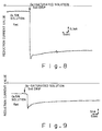
- Measurement was performed in a solution having a constant oxygen concentration by a method similar to that of
Experiment 6; a solution saturated with oxygen gas was added to this solution, and a change in the current value was investigated. The resulting graph is shown in Fig. 8. It was found that the sensor responded quickly when the solution was added, and that the speed of response was a very quick one to two seconds. - By using a carbon electrode having a diameter of 0.1 mm, an oxygen sensor having a large area was fabricated by coating the surface of the electrode with a Co-TAPP film (film thickness: 0.5 »m) using a method similar to that of
Embodiment 2. - Measurement similar to that of
Experiment 6 was performed in order to compare the sensor of Comparative Example 1 with the sensor fabricated according toEmbodiment 2. The results are illustrated in Fig. 9. It was found that current rise is slow and that five to ten seconds were required for response. -
- Oxygen sensors created in accordance with
Embodiment 2 and Comparative Example 1 were immersed in a phosphate buffer solution along with a reference electrode, current value when a potential of -0.6 V was applied to the reference electrode and the solution was stirred was compared with a case in which the solution was not stirred, and susceptibility to the influence of fluid flow was evaluated. The results are shown in Figs. 10A and 10B. With the oxygen sensor ofEmbodiment 2, current value does not change regardless of whether the solution is or is not stirred, as shown in Fig. 10A. With the sensor of Comparative Example 1, however, as shown in Fig. 10B, it was found that while current fluctuates when stirring is performed, fluctuation ceases when stirring is stopped but the current value decreases at such time. On the basis of these results, it was confirmed that the sensor fabricated in accordance withEmbodiment 2 is capable of accurate measurement without being influenced by flow of the fluid. - As described in detail above, an oxygen sensor having a quick 90% response of less than one second is obtained by using an electrode having a very small area, namely the cross section of a carbon fiber, and coating this electrode with a film having an oxygen-reducing function. In addition, the oxygen sensor is capable of measuring oxygen concentration without being influenced by other coexisting chemical substances and without being influenced by fluid flow. Furthermore, since the electrode portion is extremely small, measurement is possible with a minute amount of a sample or at a very small region.
- In an embodiment described next, an ultraminiature enzyme sensor is provided by achieving miniaturization using one filament of a carbon fiber and forming a thin film on a minute portion using electrolytic polymerization. The purpose is to realize miniaturization and high-speed response and measure substrate concentration in vitro (in tissue) or in a minute amount of a sample. A sensor is provided in which speed of response is less than three seconds for 95% response and the outer diameter of the sensor tip is less than 100 »m (where the responsive portion is less than 10 »m).
- Examples of chemical compounds which take part in enzyme reactions and are produced or consumed and exhibit electrode activity are 0₂, H₂O₂, CO₂, etc. A cobalt porphyrin polymeric film is preferred as an O₂-reducing catalytic film, a poly(4,4′-biphenol) film as an H₂O₂-oxidizing catalytic film, and a film comprising polythiophene film/silver/rhenium as a CO₂-reducing catalyst. An electrolytic polymerization process is preferred as the coating process for applying these films.
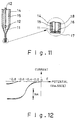
- A schematic view showing the construction of an ultraminiature enzyme sensor according to this embodiment is illustrated in Fig. 11. Reference numerals identical with those in Fig. 6 designate the same constituent substances. One end of the
carbon fiber 11 is connected to thelead wire 12 using the electricallyconductive bonding agent 13, the tip of the carbon fiber is inserted into the finely extendedglass capillary 14, and the capillary is subsequently filled with theinsulative bonding agent 15 to achieve electrical insulation. Next, a portion of the tip of this capillary electrode is cut off and the cut tip is polished to fabricate a carbon-disk electrode for an ultraminiature enzyme sensor. - By using a potentiostat and a three-electrode system having this ultraminiature disk electrode as an active electrode, a saturated sodium chloride calomel electrode (SSCE) as a reference electrode and a platinum wire as an opposing electrode, electrolysis was performed under the electrolytic conditions indicated below, thereby depositing an electrolytic polymeric film (an oxygen-reducing catalytic film) 16. Using acetonitrile containing 1 mmol/l mesotetra (o-aminophenyl) cobalt porphyrin (hereinafter abbreviated to Co-TAPP) and 0.1 mol/l sodium perchlorate, potential was swept from 0V to 1.8 V (vs. SSCE) at 50 mV/sec, after which constant-potential electrolysis was carried out for 10 minutes at 1.8 V to form a Co-TAPP polymeric film having a film thickness of 0.5 »m.
- It will be understood from the cyclic voltammogram shown in Fig. 12 that the electrode thus manufactured catalyzes the electrolytic reducing reaction of oxygen in solution. Specifically, in comparison solely with a carbon-fiber electrode, the oxygen reducing reaction occurs at a potential of -500 to -600 mV, and a steady current is obtained even at a sweep speed of 50 mV/sec.
- It was found that by using this electrode, sufficient characteristics as an electrode for a subminiature enzyme sensor were obtained, namely a response time of less than one second when the electrolytic potential was held at -0.6 V (vs. SSCE) and the concentration of oxygen in solution was changed from PO₂ = 150 mmHg to 300 mmHg. It will be understood that this oxygen-reducing catalytic-film electrode functions as an oxygen sensor with a very high speed of response.
- The surface of the electrolytic polymeric film (the oxygen-reducing catalytic film) was coated with an enzyme-fixing
film 17 by a method described below. - An oxygen-reducing catalytic-film electrode was immersed five times in a solution obtained by dissolving 100 mg/ml of glucose oxidase and 15 weight-% of bovine serum albumin in a pH 8.0 phosphate buffer solution. After the electrode was allowed to dry, a cross-linking reaction was allowed to take place for 12 hours in a glutaric aldehyde vapor of a 50% glutaric aldehyde solution. This was followed by washing with a 20% glycine solution.
- Thus, a glucose oxidase-fixing film was formed (film thickness: 10 »m) to fabricate an ultraminiature enzyme sensor.
- Constant-potential electrolysis at -0.6 V vs. SSCE was performed with a three-electrode cell using the subminiature enzyme sensor of Embodiment 4 (carbon-fiber cross section: 7.85 x 10⁻¹¹ m²) as an sectional area electrode, a saturated sodium chloride calomel electrode (SSCE) as a reference electrode and a platinum wire as an opposing electrode. A plot of current response at this time with respect to glucose concentration in the solution is shown in Fig. 13. A region of linear current response was obtained over a range of glucose concentration of 0 - 105 mg/dl. It was found that response time in this case is less than two seconds for a 95% response, which is indicative of a very high speed of response. The specimen solution was stirred gently with a stirrer at 25°C and measured using a 5 mM phosphate buffer solution (pH: 6.2).
- After an ultraminiature enzyme sensor was manufactured in the same manner as in
Embodiment 4, a glucose-permeable film 18 (20 »m) was formed by repeatedly dipping the sensor in a dichloromethane solution of 5% cellulose acetate, and allowing it to dry, three times. The enzyme-fixed film preferably is 400 Å - 50 »m, with 1 - 10 »m being particularly desirable. The enzyme is not fixed sufficiently and lifetime is short below 400 Å, and speed of response diminishes when 100 »m is exceeded. - The subminiature enzyme sensor of
Embodiment 5 was treated as inExperiment 9 and current response with respect to glucose concentration was investigated. As a result, it was found that the region of linear current covered a wide range of 0 - 240 mg/dl. It was found that speed of response in this case was less than three seconds for a 95% response, and that a slowing of the response due to the glucose-permeable film was small. - As described in detail above, the electrode area is ultraminiaturized in the enzyme sensor of the present embodiment. The following advantages are obtained as a result:
- (1) Basic concentration measurement in a living body or tissue is possible.
- (2) Measurement of trace amounts of a sample on the »l order is of course possible.
- (3) Since the sensor substrate is ultraminiaturized, response is a very quick three seconds and rapid measurement is possible.
- (4) Cost is low since inexpensive carbon fiber can be used.
- (5) A change in concentration caused by reaction is negligible owing to the very small responsive area.
- (6) The influence of solution fluidity and flow is negligible.
- It should be noted that material other than a slender carbon material, such as a metal (e.g., gold) or metal oxide [iridium oxide, indium tin oxide (ITO)], may be used as the electrically conductive substrate.
- Furthermore, though the film-coated sensors of these embodiments are typified by oxygen sensors and enzyme sensors, as stated at the beginning of the description of the embodiments, the present invention can be similarly applied to other film-coated sensors.
Claims (2)
- A film-coated sensor comprising :
a capillary (1, 14) ;
an electrically conductive substrate (2, 11), composed of carbon fibers, a carbon rod-shaped member, gold wire or a metal oxide, which is connected to a lead wire (5, 12) at one end of said capillary (1, 14) and inscribed in said capillary (1, 14), the sectional area of said electrically conductive substrate (2, 11) being less than 10⁻⁹ m²; and
a solid coating film (7, 16) which coats, to a predetermined depth, an end face of said electrically conductive substrate at another end, which is open, of said capillary (1, 14). - The film-coated sensor according to claim 1, wherein the solid coating film (7, 16) has a film which responds only to a gas or electrolyte of interest from an activated substance contained in blood or a related biological fluid.
Applications Claiming Priority (5)
| Application Number | Priority Date | Filing Date | Title |
|---|---|---|---|
| JP1741488 | 1988-01-29 | ||
| JP17414/88 | 1988-01-29 | ||
| JP63081419A JP2672561B2 (en) | 1988-01-29 | 1988-04-04 | Membrane cover sensor |
| JP81419/88 | 1988-04-04 | ||
| PCT/JP1989/000085 WO1989007262A1 (en) | 1988-01-29 | 1989-01-27 | Film-coated sensor |
Publications (3)
| Publication Number | Publication Date |
|---|---|
| EP0397868A1 EP0397868A1 (en) | 1990-11-22 |
| EP0397868A4 EP0397868A4 (en) | 1993-08-04 |
| EP0397868B1 true EP0397868B1 (en) | 1995-03-22 |
Family
ID=26353916
Family Applications (1)
| Application Number | Title | Priority Date | Filing Date |
|---|---|---|---|
| EP89901741A Expired - Lifetime EP0397868B1 (en) | 1988-01-29 | 1989-01-27 | Film-coated sensor |
Country Status (6)
| Country | Link |
|---|---|
| US (1) | US5186808A (en) |
| EP (1) | EP0397868B1 (en) |
| JP (1) | JP2672561B2 (en) |
| AU (1) | AU2939289A (en) |
| DE (1) | DE68921881T2 (en) |
| WO (1) | WO1989007262A1 (en) |
Families Citing this family (22)
| Publication number | Priority date | Publication date | Assignee | Title |
|---|---|---|---|---|
| NO903011L (en) * | 1990-07-05 | 1992-01-06 | Sinvent As | ELECTROCHEMICAL ION SELECTIVE SENSOR. |
| EP0592805A3 (en) * | 1992-09-09 | 1996-07-24 | Agency Ind Science Techn | Carbon sensor electrode and process for producing the same |
| US5503728A (en) * | 1992-09-09 | 1996-04-02 | Agency Of Industrial Science And Technology | Carbon sensor electrode and process for producing the same |
| US5611900A (en) * | 1995-07-20 | 1997-03-18 | Michigan State University | Microbiosensor used in-situ |
| US5989409A (en) * | 1995-09-11 | 1999-11-23 | Cygnus, Inc. | Method for glucose sensing |
| US6331163B1 (en) | 1998-01-08 | 2001-12-18 | Microsense Cardiovascular Systems (1196) Ltd. | Protective coating for bodily sensor |
| US7192766B2 (en) * | 2001-10-23 | 2007-03-20 | Medtronic Minimed, Inc. | Sensor containing molded solidified protein |
| US7101472B2 (en) * | 2002-03-13 | 2006-09-05 | The Charles Stark Draper Laboratory, Inc. | Microfluidic ion-selective electrode sensor system |
| US7407570B2 (en) * | 2002-03-13 | 2008-08-05 | The Charles Stark Draper Laboratory, Inc. | Disposable, self-administered electrolyte test |
| CN1754097A (en) * | 2003-02-24 | 2006-03-29 | 汤浅真 | Active oxygen species measuring device |
| US7291503B2 (en) * | 2003-05-21 | 2007-11-06 | Massachusetts Institute Of Technology | Reversible resistivity-based sensors |
| GB0316075D0 (en) * | 2003-07-09 | 2003-08-13 | Molecular Sensing Plc | Protease detection assay |
| JP2006242783A (en) * | 2005-03-04 | 2006-09-14 | Makoto Yuasa | Porphyrin electrolytic polymerization film modified platinum linear sensor |
| US9044178B2 (en) * | 2007-08-30 | 2015-06-02 | Pepex Biomedical, Llc | Electrochemical sensor and method for manufacturing |
| WO2009032760A2 (en) | 2007-08-30 | 2009-03-12 | Pepex Biomedical Llc | Electrochmical sensor and method for manufacturing |
| WO2010056878A2 (en) | 2008-11-14 | 2010-05-20 | Pepex Biomedical, Llc | Electrochemical sensor module |
| WO2010056876A2 (en) | 2008-11-14 | 2010-05-20 | Pepex Biomedical, Llc | Manufacturing electrochemical sensor module |
| US8951377B2 (en) | 2008-11-14 | 2015-02-10 | Pepex Biomedical, Inc. | Manufacturing electrochemical sensor module |
| US9504162B2 (en) | 2011-05-20 | 2016-11-22 | Pepex Biomedical, Inc. | Manufacturing electrochemical sensor modules |
| EP2925229A4 (en) | 2012-12-03 | 2017-01-25 | Pepex Biomedical, Inc. | Sensor module and method of using a sensor module |
| BR112016028536B1 (en) | 2014-06-04 | 2021-11-30 | Pepex Biomedical, Inc | SENSOR COMPRISING A SKIN DRILLING MEMBER AND A BLOOD SAMPLE ANALYSIS ZONE |
| CN104947066B (en) * | 2014-09-16 | 2017-08-15 | 山东省科学院激光研究所 | Capillary glass pipe surface plates carbon technology |
Family Cites Families (20)
| Publication number | Priority date | Publication date | Assignee | Title |
|---|---|---|---|---|
| US3476670A (en) * | 1967-04-10 | 1969-11-04 | Us Agriculture | Polarographic electrode structure |
| GB1571282A (en) * | 1976-03-11 | 1980-07-09 | City Tech | Gas sensor |
| US4134798A (en) * | 1978-03-13 | 1979-01-16 | Fmc Corporation | Isocyanurate specific electrode and method of analysis and quaternary ammonium isocyanuric acid salts therefore |
| US4198851A (en) * | 1978-05-22 | 1980-04-22 | University Of Utah | Method and structure for detecting the concentration of oxygen in a substance |
| JPS5746154A (en) * | 1980-09-05 | 1982-03-16 | Toyota Motor Corp | Detecting method for concentration of oxygen |
| DE3278334D1 (en) * | 1981-10-23 | 1988-05-19 | Genetics Int Inc | Sensor for components of a liquid mixture |
| US4563263A (en) * | 1982-01-15 | 1986-01-07 | Terumo Corporation | Selectively permeable film and ion sensor |
| JPS58200157A (en) * | 1982-05-18 | 1983-11-21 | Nippon Telegr & Teleph Corp <Ntt> | oxygen sensor |
| JPS59142451A (en) * | 1983-02-03 | 1984-08-15 | Terumo Corp | Ion sensor |
| JPS60106609U (en) * | 1983-12-26 | 1985-07-20 | 塩野義製薬株式会社 | microelectrode |
| US4615954A (en) * | 1984-09-27 | 1986-10-07 | Eltech Systems Corporation | Fast response, high rate, gas diffusion electrode and method of making same |
| KR900008847B1 (en) * | 1985-05-27 | 1990-11-30 | 테루모가부시끼가이샤 | Ion sensor and manufacturing method |
| DK626986A (en) * | 1985-12-25 | 1987-06-26 | Terumo Corp | ion sensor |
| DE3687123T2 (en) * | 1986-01-24 | 1993-05-13 | Terumo Corp | ION SENSITIVE FET PROBE. |
| JPS62180263A (en) * | 1986-02-04 | 1987-08-07 | Terumo Corp | Oxygen sensor |
| US4871442A (en) * | 1986-05-01 | 1989-10-03 | Terumo Corporation | Ion sensor |
| JPS62277547A (en) * | 1986-05-26 | 1987-12-02 | Terumo Corp | Gas sensor |
| JPS636451A (en) * | 1986-06-27 | 1988-01-12 | Terumo Corp | Enzyme sensor |
| JPS63131057A (en) * | 1986-11-20 | 1988-06-03 | Terumo Corp | Enzyme sensor |
| JPH06133644A (en) * | 1992-02-05 | 1994-05-17 | Akira Oguri | Lightweight admixture and manufacturing method thereof |
-
1988
- 1988-04-04 JP JP63081419A patent/JP2672561B2/en not_active Expired - Lifetime
-
1989
- 1989-01-27 WO PCT/JP1989/000085 patent/WO1989007262A1/en not_active Ceased
- 1989-01-27 EP EP89901741A patent/EP0397868B1/en not_active Expired - Lifetime
- 1989-01-27 AU AU29392/89A patent/AU2939289A/en not_active Abandoned
- 1989-01-27 US US07/548,931 patent/US5186808A/en not_active Expired - Fee Related
- 1989-01-27 DE DE68921881T patent/DE68921881T2/en not_active Expired - Fee Related
Also Published As
| Publication number | Publication date |
|---|---|
| AU2939289A (en) | 1989-08-25 |
| WO1989007262A1 (en) | 1989-08-10 |
| EP0397868A4 (en) | 1993-08-04 |
| EP0397868A1 (en) | 1990-11-22 |
| JP2672561B2 (en) | 1997-11-05 |
| DE68921881T2 (en) | 1995-09-14 |
| DE68921881D1 (en) | 1995-04-27 |
| US5186808A (en) | 1993-02-16 |
| JPH021536A (en) | 1990-01-05 |
Similar Documents
| Publication | Publication Date | Title |
|---|---|---|
| US5186808A (en) | Film-coated sensor | |
| US4927516A (en) | Enzyme sensor | |
| US5205920A (en) | Enzyme sensor and method of manufacturing the same | |
| Zhang et al. | Glucose nanosensor based on Prussian‐blue modified carbon‐fiber cone nanoelectrode and an integrated reference electrode | |
| JP2740587B2 (en) | Micro composite electrode and method of manufacturing the same | |
| US4861454A (en) | Oxygen sensor | |
| EP0304933A2 (en) | A reference electrode and a measuring apparatus using the same | |
| US5078856A (en) | Ion carrier membrane, and ion sensor having same | |
| US5269903A (en) | Microbioelectrode and method of fabricating the same | |
| US5256271A (en) | Method of immobilizing biofunctional material, and element prepared thereby, and measurement by using the same element | |
| Jaffari et al. | Novel hexacyanoferrate (III)-modified carbon electrodes: application in miniaturized biosensors with potential for in vivo glucose sensing | |
| WO1997015827A9 (en) | Coated wire sensor | |
| EP0592805A2 (en) | Carbon sensor electrode and process for producing the same | |
| Yang et al. | An Integrated Needle‐Type Biosensor for Intravascular Glucose and Lactate Monitoring | |
| Ikariyama et al. | High performance micro-enzyme sensor using platinized microelectrode. | |
| JPH0557538B2 (en) | ||
| JPH05203608A (en) | Biosensor | |
| JP3258365B2 (en) | Biosensor | |
| JP3778680B2 (en) | Cathode for oxygen electrode | |
| JP3035572B2 (en) | Cholesterol sensor | |
| JP2866865B2 (en) | Manufacturing method of enzyme sensor | |
| JPH021537A (en) | Oxygen sensor | |
| JPS6162855A (en) | Electrode for measuring concentration of electrochemically active substance | |
| JPH0430544B2 (en) | ||
| JPH0694671A (en) | Carbon sensor electrode and prodcuction thereof |
Legal Events
| Date | Code | Title | Description |
|---|---|---|---|
| PUAI | Public reference made under article 153(3) epc to a published international application that has entered the european phase |
Free format text: ORIGINAL CODE: 0009012 |
|
| 17P | Request for examination filed |
Effective date: 19900726 |
|
| AK | Designated contracting states |
Kind code of ref document: A1 Designated state(s): BE DE FR IT NL SE |
|
| A4 | Supplementary search report drawn up and despatched |
Effective date: 19930614 |
|
| AK | Designated contracting states |
Kind code of ref document: A4 Designated state(s): BE DE FR IT NL SE |
|
| 17Q | First examination report despatched |
Effective date: 19931116 |
|
| GRAA | (expected) grant |
Free format text: ORIGINAL CODE: 0009210 |
|
| AK | Designated contracting states |
Kind code of ref document: B1 Designated state(s): BE DE FR IT NL SE |
|
| PG25 | Lapsed in a contracting state [announced via postgrant information from national office to epo] |
Ref country code: NL Free format text: LAPSE BECAUSE OF FAILURE TO SUBMIT A TRANSLATION OF THE DESCRIPTION OR TO PAY THE FEE WITHIN THE PRESCRIBED TIME-LIMIT Effective date: 19950322 Ref country code: BE Effective date: 19950322 |
|
| REF | Corresponds to: |
Ref document number: 68921881 Country of ref document: DE Date of ref document: 19950427 |
|
| ITF | It: translation for a ep patent filed | ||
| PG25 | Lapsed in a contracting state [announced via postgrant information from national office to epo] |
Ref country code: SE Effective date: 19950622 |
|
| ET | Fr: translation filed | ||
| NLV1 | Nl: lapsed or annulled due to failure to fulfill the requirements of art. 29p and 29m of the patents act | ||
| PLBE | No opposition filed within time limit |
Free format text: ORIGINAL CODE: 0009261 |
|
| STAA | Information on the status of an ep patent application or granted ep patent |
Free format text: STATUS: NO OPPOSITION FILED WITHIN TIME LIMIT |
|
| 26N | No opposition filed | ||
| PGFP | Annual fee paid to national office [announced via postgrant information from national office to epo] |
Ref country code: DE Payment date: 19991231 Year of fee payment: 12 |
|
| PGFP | Annual fee paid to national office [announced via postgrant information from national office to epo] |
Ref country code: FR Payment date: 20000112 Year of fee payment: 12 |
|
| PG25 | Lapsed in a contracting state [announced via postgrant information from national office to epo] |
Ref country code: FR Free format text: LAPSE BECAUSE OF NON-PAYMENT OF DUE FEES Effective date: 20010928 |
|
| PG25 | Lapsed in a contracting state [announced via postgrant information from national office to epo] |
Ref country code: DE Free format text: LAPSE BECAUSE OF NON-PAYMENT OF DUE FEES Effective date: 20011101 |
|
| REG | Reference to a national code |
Ref country code: FR Ref legal event code: ST |
|
| PG25 | Lapsed in a contracting state [announced via postgrant information from national office to epo] |
Ref country code: IT Free format text: LAPSE BECAUSE OF NON-PAYMENT OF DUE FEES Effective date: 20050127 |