EP0397850B1 - Brake apparatus with blind cable installing means - Google Patents
Brake apparatus with blind cable installing means Download PDFInfo
- Publication number
- EP0397850B1 EP0397850B1 EP90901101A EP90901101A EP0397850B1 EP 0397850 B1 EP0397850 B1 EP 0397850B1 EP 90901101 A EP90901101 A EP 90901101A EP 90901101 A EP90901101 A EP 90901101A EP 0397850 B1 EP0397850 B1 EP 0397850B1
- Authority
- EP
- European Patent Office
- Prior art keywords
- spring
- lever
- backing plate
- ramp
- assembly
- Prior art date
- Legal status (The legal status is an assumption and is not a legal conclusion. Google has not performed a legal analysis and makes no representation as to the accuracy of the status listed.)
- Expired - Lifetime
Links
- 239000002184 metal Substances 0.000 claims abstract description 8
- 230000001154 acute effect Effects 0.000 claims abstract description 7
- 238000006073 displacement reaction Methods 0.000 claims description 5
- 238000003780 insertion Methods 0.000 claims description 5
- 230000037431 insertion Effects 0.000 claims description 5
- 230000000717 retained effect Effects 0.000 claims description 2
- 238000010276 construction Methods 0.000 abstract description 4
- 238000004519 manufacturing process Methods 0.000 description 6
- 230000004048 modification Effects 0.000 description 3
- 238000012986 modification Methods 0.000 description 3
- 230000000712 assembly Effects 0.000 description 2
- 238000000429 assembly Methods 0.000 description 2
- 238000005452 bending Methods 0.000 description 2
- 238000009434 installation Methods 0.000 description 2
- 230000000295 complement effect Effects 0.000 description 1
- 238000003754 machining Methods 0.000 description 1
Images


Classifications
-
- F—MECHANICAL ENGINEERING; LIGHTING; HEATING; WEAPONS; BLASTING
- F16—ENGINEERING ELEMENTS AND UNITS; GENERAL MEASURES FOR PRODUCING AND MAINTAINING EFFECTIVE FUNCTIONING OF MACHINES OR INSTALLATIONS; THERMAL INSULATION IN GENERAL
- F16D—COUPLINGS FOR TRANSMITTING ROTATION; CLUTCHES; BRAKES
- F16D51/00—Brakes with outwardly-movable braking members co-operating with the inner surface of a drum or the like
- F16D51/16—Brakes with outwardly-movable braking members co-operating with the inner surface of a drum or the like shaped as brake-shoes pivoted on a fixed or nearly-fixed axis
- F16D51/18—Brakes with outwardly-movable braking members co-operating with the inner surface of a drum or the like shaped as brake-shoes pivoted on a fixed or nearly-fixed axis with two brake-shoes
- F16D51/20—Brakes with outwardly-movable braking members co-operating with the inner surface of a drum or the like shaped as brake-shoes pivoted on a fixed or nearly-fixed axis with two brake-shoes extending in opposite directions from their pivots
- F16D51/22—Brakes with outwardly-movable braking members co-operating with the inner surface of a drum or the like shaped as brake-shoes pivoted on a fixed or nearly-fixed axis with two brake-shoes extending in opposite directions from their pivots mechanically actuated
-
- B—PERFORMING OPERATIONS; TRANSPORTING
- B60—VEHICLES IN GENERAL
- B60T—VEHICLE BRAKE CONTROL SYSTEMS OR PARTS THEREOF; BRAKE CONTROL SYSTEMS OR PARTS THEREOF, IN GENERAL; ARRANGEMENT OF BRAKING ELEMENTS ON VEHICLES IN GENERAL; PORTABLE DEVICES FOR PREVENTING UNWANTED MOVEMENT OF VEHICLES; VEHICLE MODIFICATIONS TO FACILITATE COOLING OF BRAKES
- B60T11/00—Transmitting braking action from initiating means to ultimate brake actuator without power assistance or drive or where such assistance or drive is irrelevant
- B60T11/04—Transmitting braking action from initiating means to ultimate brake actuator without power assistance or drive or where such assistance or drive is irrelevant transmitting mechanically
- B60T11/046—Using cables
-
- F—MECHANICAL ENGINEERING; LIGHTING; HEATING; WEAPONS; BLASTING
- F16—ENGINEERING ELEMENTS AND UNITS; GENERAL MEASURES FOR PRODUCING AND MAINTAINING EFFECTIVE FUNCTIONING OF MACHINES OR INSTALLATIONS; THERMAL INSULATION IN GENERAL
- F16D—COUPLINGS FOR TRANSMITTING ROTATION; CLUTCHES; BRAKES
- F16D65/00—Parts or details
- F16D65/14—Actuating mechanisms for brakes; Means for initiating operation at a predetermined position
- F16D65/16—Actuating mechanisms for brakes; Means for initiating operation at a predetermined position arranged in or on the brake
- F16D65/22—Actuating mechanisms for brakes; Means for initiating operation at a predetermined position arranged in or on the brake adapted for pressing members apart, e.g. for drum brakes
-
- F—MECHANICAL ENGINEERING; LIGHTING; HEATING; WEAPONS; BLASTING
- F16—ENGINEERING ELEMENTS AND UNITS; GENERAL MEASURES FOR PRODUCING AND MAINTAINING EFFECTIVE FUNCTIONING OF MACHINES OR INSTALLATIONS; THERMAL INSULATION IN GENERAL
- F16C—SHAFTS; FLEXIBLE SHAFTS; ELEMENTS OR CRANKSHAFT MECHANISMS; ROTARY BODIES OTHER THAN GEARING ELEMENTS; BEARINGS
- F16C1/00—Flexible shafts; Mechanical means for transmitting movement in a flexible sheathing
- F16C1/10—Means for transmitting linear movement in a flexible sheathing, e.g. "Bowden-mechanisms"
- F16C1/12—Arrangements for transmitting movement to or from the flexible member
-
- F—MECHANICAL ENGINEERING; LIGHTING; HEATING; WEAPONS; BLASTING
- F16—ENGINEERING ELEMENTS AND UNITS; GENERAL MEASURES FOR PRODUCING AND MAINTAINING EFFECTIVE FUNCTIONING OF MACHINES OR INSTALLATIONS; THERMAL INSULATION IN GENERAL
- F16C—SHAFTS; FLEXIBLE SHAFTS; ELEMENTS OR CRANKSHAFT MECHANISMS; ROTARY BODIES OTHER THAN GEARING ELEMENTS; BEARINGS
- F16C2326/00—Articles relating to transporting
- F16C2326/01—Parts of vehicles in general
-
- F—MECHANICAL ENGINEERING; LIGHTING; HEATING; WEAPONS; BLASTING
- F16—ENGINEERING ELEMENTS AND UNITS; GENERAL MEASURES FOR PRODUCING AND MAINTAINING EFFECTIVE FUNCTIONING OF MACHINES OR INSTALLATIONS; THERMAL INSULATION IN GENERAL
- F16D—COUPLINGS FOR TRANSMITTING ROTATION; CLUTCHES; BRAKES
- F16D2125/00—Components of actuators
- F16D2125/18—Mechanical mechanisms
- F16D2125/58—Mechanical mechanisms transmitting linear movement
- F16D2125/60—Cables or chains, e.g. Bowden cables
-
- F—MECHANICAL ENGINEERING; LIGHTING; HEATING; WEAPONS; BLASTING
- F16—ENGINEERING ELEMENTS AND UNITS; GENERAL MEASURES FOR PRODUCING AND MAINTAINING EFFECTIVE FUNCTIONING OF MACHINES OR INSTALLATIONS; THERMAL INSULATION IN GENERAL
- F16D—COUPLINGS FOR TRANSMITTING ROTATION; CLUTCHES; BRAKES
- F16D2125/00—Components of actuators
- F16D2125/18—Mechanical mechanisms
- F16D2125/58—Mechanical mechanisms transmitting linear movement
- F16D2125/60—Cables or chains, e.g. Bowden cables
- F16D2125/62—Fixing arrangements therefor, e.g. cable end attachments
Definitions
- This invention relates to an improved parking brake arrangement of the blind cable installation type.
- a parking brake assembly in which blind cable connecting means are provided for connecting a flexible resilient parking brake cable with a parking brake lever, use being made of a helical guide spring for guiding the cable toward an inclined ramp surface on the lever.
- the fabrication of the ramp portion of the lever is rather complex and requires a number of manufacturing steps, owing to the provision of a rather unique slot configuration in the ramp surface, and the requirement for a curved wall surface with a retaining lip extremity for maintaining the cable extremity in line during the blind assembly of the parking brake cable.
- the manufacture of the parking brake lever requires a relatively large number of manufacturing steps, thereby increasing the resulting cost of the lever.
- disassembly of the cable member from the lever is most awkward and difficult to achieve.
- the present invention was developed to avoid the above and other drawbacks of the known blind parking brake assembly, and to provide an improved construction in which the parking brake lever is easily and economically fabricated from a blank of flat metal stock.
- a primary object of the present invention is to provide an improved parking brake assembly of the blind cable connection type in which the parking brake lever is formed from a blank of flat metal stock and includes an inclined ramp surface contained in a plane that is parallel with the axis of the lever and inclined at an acute angle relative to the axis of the cable, the ramp being bifurcated in a simple manner to define a slot that receives the cable member when in the connection condition.
- a pair of cooperating semi-circular arms integral with the lever define a generally annular spring support portion spaced forwardly of the ramp surface, which support portion receives one end of the guide spring.
- the guide spring includes portions of compacted tightly-wound coil turns for improving the connection of the spring to the lever and/or the backing plate.
- the tightly wound turns are provided at the ends of the spring.
- the turns of the spring portion that extend through the opening in the backing plate are tightly wound to prevent lateral movement of the spring relative to the opening.
- the tightly wound turns enhance the entry of the spring end into the generally annular spring support portion of the lever.
- the tightly wound turns define bell-shaped portions of enlarged outer diameter spaced from the associated spring ends.
- one bell-shaped portion limits the extent of outward travel of the spring relative to the backing plate opening in which the spring is mounted, and the other bell-shaped portion limits the extent to which the spring enters the annular spring support portion of the lever.
- a further object of the invention is to provide a lever construction having the aforementioned bifurcated ramp structure, whereby the flexible parking brake cable member may be readily connected and disconnected from the lever.
- the lever is fabricated from a blank of flat metal stock by a limited number of simple pressing, forming and machining steps, thereby reducing the cost of the lever.
- the annular spring support portion on the lever is formed from two oppositely extending tabs that are rolled to define cooperating semi-circular arms.
- the semi-circular arms may be provided with radially inwardly extending tabs that serve as stops for the springs.
- the ramp portion of the lever includes an integral extension arranged to abut the associated brake shoe during the blind assembly of the cable to the ramp portion, thereby spacing the ramp portion from the shoe to a sufficient extent to permit the cable extremity to ride over the peak of the ramp and to permit entry of the cable member into the retaining slot contained in the ramp.
- Still another object of the invention is to provide a blind entry cable installation arrangement in which the manufacturer is permitted to completely assemble the brake assemblies and drums to the axle housing member at one location and to install the flexible cable member at another time or location, thereby virtually eliminating the possibility of damaging parts and eliminating the need for costly and time consuming reworking to remove and replace the damaged parts, resulting in a considerable cost savings to the manufacturer.
- a further object of the invention is to provide a mechanical brake actuating lever means that is simple and economical to manufacture and assemble and that is readily adaptable to a variety of brake type and size applications.
- the blind-connection parking brake assembly in accordance with the present invention is defined in claim 1.
- the brake apparatus for a vehicle includes a stationary backing plate 2 to which are connected a pair of brake shoes 4 and 6 that are operable by a conventional brake cylinder 8.
- a rigid strut element 10 Arranged between the brake shoes is a rigid strut element 10, and conventional threaded adjusting means 12 are connected with the brake shoes on the opposite side of the strut member from the brake cylinder 8.
- a parking brake lever 14 is pivotally mounted on the strut member 10 for operating the brake shoes toward a locked condition, said parking brake lever being pivotally operable about pivot axis 15 by the inner cable member 16 of a parking brake cable assembly including an outer conduit member 18.
- the inner cable member extends longitudinally through a helical guide spring 20 that extends at one end through an opening contained in the backing plate 2, and the other end of the spring being connected with a transversely arranged spring support portion 14a integral with the parking brake lever 14.
- a ramp portion 14b Spaced from the spring support portion 14a is a ramp portion 14b including an inclined ramp wall 14c having a ramp surface that extends at an acute angle ⁇ to the axis of the spring support portion 14a, as shown in Fig. 2, said ramp surface also being inclined at an acute complementary angle ⁇ to the longitudinal axis of lever 14.
- the ramp portion 14b has a generally U-shaped cross-sectional configuration and includes a ramp wall 14c which contains a vertical slot 24 that receives the inner cable member 16 when the cable is connected with the ramp portion 14b, as will described below.
- the enlarged extremity 16a of the inner cable member 16 is progressively introduced via the guide spring 20 until it passes through the annular spring support portion 14a of the lever 14 as shown in Fig. 5a.
- the extremity 16a is guided up the ramp surface 14c as shown in Figs. 5b and 5c.
- the cable extremity 16a enters the enlarged upper end of slot 24 as shown in Fig.
- the enlarged portion 16a rides over the corresponding edge of the slot and the cable, owing to its inherent resiliency, returns to its original linear configuration as shown in Figs. 5e and 5f, whereupon the enlarged extremity 16a seats in a corresponding recess contained in the ramp portion 14b, thereby to lock the inner cable member 16 with the lever 14, as shown in Fig. 5f.
- tensioning of the cable causes lever 14 to pivot in the clockwise direction about the pivot axis 14 defined by the strut 10, thereby to displace the brake shoes outwardly toward positions in locking engagement with the associated brake drum.
- the end extremity 16a of the inner cable member is contained between the parallel surfaces of the tab portion 14b and the lever 14 as the cable is displaced toward the locked condition shown in Fig. 5f, and therefore the inner cable member is relatively inaccessible in the event it should be wished to disassemble the same from the parking brake lever 14.
- the lever 14 is preferably fabricated from a blank of flat metal stock, a relatively large number of folding and pressing steps being required to form the slotted ramp portion 14 of the lever.
- the generally annular spring support portion 14a is formed by bending a single tab member into a generally circular configuration, thereby to define an axial opening for receiving the corresponding end of the helical guide spring 20.
- the improved parking brake apparatus of the present invention includes an improved parking brake lever 114 that is pressed and formed from a blank of flat metal stock and includes at one end a generally annular spring support portion 114a, and a ramp portion 114b.
- the transversely arranged annular spring support portion 114a includes a pair of integral arm portions 114g and 114h (Fig. 8) that are bent to define cooperating semi-circular configurations, thereby to define a generally annular opening for receiving the associated end of the helical guide spring 120.
- the ramp wall surface 114c has an angle of inclination ⁇ ′ relative to the axis of the spring support portion 114a, as shown in Fig. 9, said ramp surface being contained in a plane generally parallel with the longitudinal axis of lever 114.
- This ramp wall 114c is bifurcated by means of a simple slot opening 140 that extends downwardly from the upper edge of the ramp wall 114c.
- the ramp portion 114b includes an extension 114f that extends outwardly from the right hand side of the lever as shown in Figs. 7 and 10a thereby to engage the associated brake shoe 106 to space the ramp wall 114c from the brake shoe and to permit the connection of the inner brake cable member 116 to the lever 114. More particularly, as the inner brake cable is progressively introduced through the end portion of the helical guide spring 120, though the opening 122 in the backing plate, through the guide spring 120, and through the spring support portion 114a, the enlarged extremity 116a engages the ramp surface 114c, as shown in Figs.
- the inner cable member may be readily disassembled from the parking brake lever. More particularly, as shown in Fig. 10j, there is provided a space 142 between the inner cable member 116 and the adjacent lever surface, thereby to permit the insertion of a suitable screwdriver, awl or the like to lift the inner cable member to the position of Fig. 10h, whereupon the inner cable member 116 may be laterally displaced from the lever 114, and may be longitudinally withdrawn from the brake assembly via the helical guide spring 120.
- the ramp wall 114c is maintained spaced from the associated surface of the brake shoe 116 by the extension 114f, as shown in phantom in Figure 10a, whereby interference with the enlarged end portion 116a by the brake shoe 106 is avoided.
- the generally-annular spring support portion 214a is defined by a pair of cooperating semi-circular tab portions 214g and 214h, as in the previous embodiment.
- the arms 214g and 214h are provided with radially inwardly directed stop tabs 214i and 214j, respectively, as shown in Fig. 13.
- the stop tabs limit the extent of insertion of the spring 220, as shown in Fig. 15a.
- the ramp surface is inclined to the axis of the spring support portion 214a by the acute angle ⁇ ⁇ , which ramp surface is contained in a plane generally parallel with the longitudinal axis of the lever 214.
- the cable is progressively introduced via the guide spring to cause the enlarged extremity 216a to ride up the inclined ramp surface 214c until the enlarged extremity rides over the upper edge of the inclined ramp wall 214c (as shown in Fig. 15h), whereupon the inner cable member 216 is received by the slot 240, and the enlarged head portion 216a is seated behind the inclined ramp wall 214c, thereby to connect the inner cable member 216 with the parking brake lever 214.
- the parking brake lever 214 is formed from a blank of flat metal stock by a minimum number of simple pressing and forming steps.
- the inclined wall 214c is deformed upwardly from the plane of the lever 214, whereupon the slot 240 is machined in the ramp wall 214c to define the bifurcated portions 214m and 214n.
- the spring support portion 214a is formed merely by bending upwardly in a semi-circular configuration the integral arm portions 214g and 214h.
- the parking brake lever is formed by a limited number of manufacturing operations, and at a minimal cost.
- the helical guide spring is provided with selected portions having tightly wound turns, thereby to improve the connection of the spring with the backing plate and/or the parking brake lever.
- the spring 320 is provided with a bell-shaped enlarged portion 320a of tightly wound turns adjacent the backing plate 302, thereby to limit the extent of travel of the spring outwardly of the backing plate. At its right hand end, the spring 320 extends within the spring support portion 314a of the parking brake lever 314.
- the spring includes bell shaped portions 420a and 420b spaced from the spring ends, thereby to limit the outward extent of travel of the spring 420 relative to the backing plate 402, and the inward extent of travel of the spring relative to the spring support portion 414a of the parking brake lever 414.
- the spring is accurately positioned and maintained connected with the backing plate 402 and the parking brake 414 when in the assembled condition of Fig. 17.
- the spring is provided at one end extremity with a tightly wound portion 520a that extends within the backing plate opening, and at the other end the spring includes a tightly wound extremity 420b that extends within the generally annular spring support portion 514a of a parking brake lever 514. Owing to the tightly wound turns of the portion 520a, lateral displacement of the spring relative to the opening in the backing plate 502 is prevented, and at the other end, the tightly wound spring portion 520b permits simple entry of the spring end within the annular spring support 514a.
- the spring extends to some extent at one end through the opening contained in the backing plate.
- the outer conduit member 617 is provided with a self-connecting fitting 650 as is known in the art, for example, as shown by the Gordy et al Reissue Patent No. US-RE-30 850.
- the enlarged end extremity 616a of the inner cable member is introduced into the protruding end portion 620c of the spring 620, whereupon the parking brake conduit is progressively introduced until the fitting 650 is snapped within the opening contained in the backing plate 602, as shown in Fig. 21.
- the spring 620 has been compressed by the fitting 650 to the point that the bell-shaped portion 620a and the end portion 620c of the spring 620 are now on the right hand side of the backing plate 620 of Fig. 21.
Landscapes
- Engineering & Computer Science (AREA)
- General Engineering & Computer Science (AREA)
- Mechanical Engineering (AREA)
- Transportation (AREA)
- Braking Arrangements (AREA)
- Flexible Shafts (AREA)
- Braking Elements And Transmission Devices (AREA)
- Braking Systems And Boosters (AREA)
Abstract
Description
- This invention relates to an improved parking brake arrangement of the blind cable installation type.
- In the prior Jaksic patent US-A-4 753 325 a parking brake assembly is disclosed in which blind cable connecting means are provided for connecting a flexible resilient parking brake cable with a parking brake lever, use being made of a helical guide spring for guiding the cable toward an inclined ramp surface on the lever. As the extremity of the cable end progressively rides up the ramp surface during insertion of the inner cable member via the guide spring, a position is reached in which the cable extremity extends through an opening in the ramp surface, whereby the cable is introduced into a retaining slot to automatically connect the cable end with the lever. In this known construction, the fabrication of the ramp portion of the lever is rather complex and requires a number of manufacturing steps, owing to the provision of a rather unique slot configuration in the ramp surface, and the requirement for a curved wall surface with a retaining lip extremity for maintaining the cable extremity in line during the blind assembly of the parking brake cable. Thus, the manufacture of the parking brake lever requires a relatively large number of manufacturing steps, thereby increasing the resulting cost of the lever. Furthermore, owing to the provision of the aforementioned curved wall with the overhanging retaining lip, disassembly of the cable member from the lever is most awkward and difficult to achieve.
- The present invention was developed to avoid the above and other drawbacks of the known blind parking brake assembly, and to provide an improved construction in which the parking brake lever is easily and economically fabricated from a blank of flat metal stock.
- A primary object of the present invention is to provide an improved parking brake assembly of the blind cable connection type in which the parking brake lever is formed from a blank of flat metal stock and includes an inclined ramp surface contained in a plane that is parallel with the axis of the lever and inclined at an acute angle relative to the axis of the cable, the ramp being bifurcated in a simple manner to define a slot that receives the cable member when in the connection condition. A pair of cooperating semi-circular arms integral with the lever define a generally annular spring support portion spaced forwardly of the ramp surface, which support portion receives one end of the guide spring.
- According to another object of the invention, the guide spring includes portions of compacted tightly-wound coil turns for improving the connection of the spring to the lever and/or the backing plate. In one embodiment, the tightly wound turns are provided at the ends of the spring. Thus, the turns of the spring portion that extend through the opening in the backing plate are tightly wound to prevent lateral movement of the spring relative to the opening. At the other end, the tightly wound turns enhance the entry of the spring end into the generally annular spring support portion of the lever. In a second spring embodiment, the tightly wound turns define bell-shaped portions of enlarged outer diameter spaced from the associated spring ends. Thus, one bell-shaped portion limits the extent of outward travel of the spring relative to the backing plate opening in which the spring is mounted, and the other bell-shaped portion limits the extent to which the spring enters the annular spring support portion of the lever.
- A further object of the invention is to provide a lever construction having the aforementioned bifurcated ramp structure, whereby the flexible parking brake cable member may be readily connected and disconnected from the lever.
- According to another object of the invention, the lever is fabricated from a blank of flat metal stock by a limited number of simple pressing, forming and machining steps, thereby reducing the cost of the lever. According to the preferred embodiment, the annular spring support portion on the lever is formed from two oppositely extending tabs that are rolled to define cooperating semi-circular arms. In order to limit movement of the spring end relative to this spring support portion, the semi-circular arms may be provided with radially inwardly extending tabs that serve as stops for the springs.
- According to a further feature of the invention, the ramp portion of the lever includes an integral extension arranged to abut the associated brake shoe during the blind assembly of the cable to the ramp portion, thereby spacing the ramp portion from the shoe to a sufficient extent to permit the cable extremity to ride over the peak of the ramp and to permit entry of the cable member into the retaining slot contained in the ramp.
- Still another object of the invention is to provide a blind entry cable installation arrangement in which the manufacturer is permitted to completely assemble the brake assemblies and drums to the axle housing member at one location and to install the flexible cable member at another time or location, thereby virtually eliminating the possibility of damaging parts and eliminating the need for costly and time consuming reworking to remove and replace the damaged parts, resulting in a considerable cost savings to the manufacturer.
- A further object of the invention is to provide a mechanical brake actuating lever means that is simple and economical to manufacture and assemble and that is readily adaptable to a variety of brake type and size applications.
- The blind-connection parking brake assembly in accordance with the present invention is defined in claim 1.
- Other objects and advantages of the invention will become apparent from a study of the following specification, when viewed in the light of the accompanying drawings, in which:
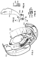
- Fig. 1 is a perspective front view of a modification of the prior art parking brake apparatus with blind cable connecting means.
- Fig. 2 is a front elevational view of the parking brake lever of Fig. 1;
- Fig. 3 is a detailed right side view of the lever taken along line 3-3 of Fig. 1;
- Fig. 4 is a sectional view taken along line 4-4 of Fig. 2;
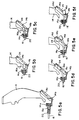
- Fig. 5a-5f are detailed front elevational views, with certain parts broken away for clarity, illustrating the manner of blind cable connection of the flexible inner brake cable member with the lever of Figs. 1-4;
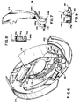
- Fig. 6 is a perspective front view of the improved parking brake assembly of the present invention;
- Fig. 7 and 8 are front elevation and right side views, respectively, of the parking brake lever of Fig. 6;
- Fig. 9 is a sectional view taken along line 9-9 of Fig. 7;
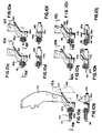
- Figs. 10a-10j are detailed elevation and corresponding sectional views respectively, illustrating the blind cable connection of the inner brake cable member to the lever of Fig. 6;
- Fig. 11 is a perspective view of a modified second embodiment of the improved parking brake apparatus of the present invention as applied to one rear wheel of the vehicle;
- Fig. 12 is a front elevational view of a reversed modification of the lever of Fig. 11, and Figs. 13 and 14 are sectional views taken along lines 13-13 and 14-14 of Fig. 12, respectively;
- Figs. 15a-15j are detailed elevation and companion sectional views respectively, illustrating the blind cable connection of the inner brake cable member to the lever of Fig. 11;
- Figs. 16 and 17 illustrate parking brake lever and cable assemblies including first and second guide spring embodiments, respectively;
- Fig. 18 illustrates a third guide spring embodiment arranged between a backing plate and the associated parking brake lever; and
- Figs. 19-21 illustrate the manner in which the guide spring is longitudinally compressed during the connection to the backing plate of a self-connecting fitting on an outer conduit member.
- Referring first more particularly to Figs. 1-4, the brake apparatus for a vehicle includes a stationary backing plate 2 to which are connected a pair of
brake shoes 4 and 6 that are operable by aconventional brake cylinder 8. Arranged between the brake shoes is arigid strut element 10, and conventional threaded adjusting means 12 are connected with the brake shoes on the opposite side of the strut member from thebrake cylinder 8. Aparking brake lever 14 is pivotally mounted on thestrut member 10 for operating the brake shoes toward a locked condition, said parking brake lever being pivotally operable aboutpivot axis 15 by theinner cable member 16 of a parking brake cable assembly including anouter conduit member 18. The inner cable member extends longitudinally through ahelical guide spring 20 that extends at one end through an opening contained in the backing plate 2, and the other end of the spring being connected with a transversely arrangedspring support portion 14a integral with theparking brake lever 14. Spaced from thespring support portion 14a is aramp portion 14b including aninclined ramp wall 14c having a ramp surface that extends at an acute angle α to the axis of thespring support portion 14a, as shown in Fig. 2, said ramp surface also being inclined at an acute complementary angle β to the longitudinal axis oflever 14. Thus, as shown in Fig. 4, theramp portion 14b has a generally U-shaped cross-sectional configuration and includes aramp wall 14c which contains avertical slot 24 that receives theinner cable member 16 when the cable is connected with theramp portion 14b, as will described below. - Referring now to Figs. 5a-5f, to connect the inner cable member with the
lever 14, the enlargedextremity 16a of theinner cable member 16 is progressively introduced via theguide spring 20 until it passes through the annularspring support portion 14a of thelever 14 as shown in Fig. 5a. When the rounded extremity of theinner cable member 16 engages theramp wall surface 14c as shown in Fig. 5b, theextremity 16a is guided up theramp surface 14c as shown in Figs. 5b and 5c. When thecable extremity 16a enters the enlarged upper end ofslot 24 as shown in Fig. 5d, the enlargedportion 16a rides over the corresponding edge of the slot and the cable, owing to its inherent resiliency, returns to its original linear configuration as shown in Figs. 5e and 5f, whereupon the enlargedextremity 16a seats in a corresponding recess contained in theramp portion 14b, thereby to lock theinner cable member 16 with thelever 14, as shown in Fig. 5f. Following connection of the inner cable member to the lever, tensioning of the cable causeslever 14 to pivot in the clockwise direction about thepivot axis 14 defined by thestrut 10, thereby to displace the brake shoes outwardly toward positions in locking engagement with the associated brake drum. - As shown in Figs. 5b-5f, the
end extremity 16a of the inner cable member is contained between the parallel surfaces of thetab portion 14b and thelever 14 as the cable is displaced toward the locked condition shown in Fig. 5f, and therefore the inner cable member is relatively inaccessible in the event it should be wished to disassemble the same from theparking brake lever 14. Thelever 14 is preferably fabricated from a blank of flat metal stock, a relatively large number of folding and pressing steps being required to form the slottedramp portion 14 of the lever. Furthermore, the generally annularspring support portion 14a is formed by bending a single tab member into a generally circular configuration, thereby to define an axial opening for receiving the corresponding end of thehelical guide spring 20. - Referring now to Figs. 6-9, the improved parking brake apparatus of the present invention includes an improved
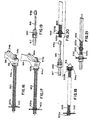
parking brake lever 114 that is pressed and formed from a blank of flat metal stock and includes at one end a generally annular spring support portion 114a, and aramp portion 114b. The transversely arranged annular spring support portion 114a includes a pair ofintegral arm portions helical guide spring 120. Theramp wall surface 114c, has an angle of inclination α′ relative to the axis of the spring support portion 114a, as shown in Fig. 9, said ramp surface being contained in a plane generally parallel with the longitudinal axis oflever 114. Thisramp wall 114c is bifurcated by means of asimple slot opening 140 that extends downwardly from the upper edge of theramp wall 114c. - In accordance with an important feature of this embodiment, the
ramp portion 114b includes anextension 114f that extends outwardly from the right hand side of the lever as shown in Figs. 7 and 10a thereby to engage the associatedbrake shoe 106 to space theramp wall 114c from the brake shoe and to permit the connection of the innerbrake cable member 116 to thelever 114. More particularly, as the inner brake cable is progressively introduced through the end portion of thehelical guide spring 120, though theopening 122 in the backing plate, through theguide spring 120, and through the spring support portion 114a, theenlarged extremity 116a engages theramp surface 114c, as shown in Figs. 10c and 10d, whereupon therounded extremity 116a rides up theramp surface 114c, as shown in Figs. 10e and 10f. Further insertion of theinner cable member 116 causes theenlarged portion 116a to ride over the upper edge of the ramp wall 114 (Figs. 10g and 10h), whereupon theinner cable member 116 is laterally displaced downwardly through theslot 140 to the position of Figs. 10i and 10j, whereupon theenlarged head portion 116a reaches a seated position behind thebifurcated ramp portion 114c, and is retained in this position as shown in Fig. 10j. The inner cable member is now connected with theparking brake lever 114, whereupon tensioning of theinner cable member 116 causes pivotal movement of thelever 114 to lock the brake shoes against the associated drum. - It is important to note that in the improved embodiment of Figs. 6-10, the inner cable member may be readily disassembled from the parking brake lever. More particularly, as shown in Fig. 10j, there is provided a space 142 between the
inner cable member 116 and the adjacent lever surface, thereby to permit the insertion of a suitable screwdriver, awl or the like to lift the inner cable member to the position of Fig. 10h, whereupon theinner cable member 116 may be laterally displaced from thelever 114, and may be longitudinally withdrawn from the brake assembly via thehelical guide spring 120. During the assembly and disassembly of the apparatus, theramp wall 114c is maintained spaced from the associated surface of thebrake shoe 116 by theextension 114f, as shown in phantom in Figure 10a, whereby interference with theenlarged end portion 116a by thebrake shoe 106 is avoided. - Referring now to the second embodiment of Figs. 11-15, the generally-annular spring support portion 214a is defined by a pair of cooperating
semi-circular tab portions helical guide spring 220 in the direction of theinclined ramp portion 214b, thearms stop tabs spring 220, as shown in Fig. 15a. Referring to Fig. 15b, the ramp surface is inclined to the axis of the spring support portion 214a by the acute angle α˝, which ramp surface is contained in a plane generally parallel with the longitudinal axis of thelever 214. As shown in Figs. 15c-15j, in order to connect theinner cable member 216 to theparking brake lever 214, the cable is progressively introduced via the guide spring to cause theenlarged extremity 216a to ride up theinclined ramp surface 214c until the enlarged extremity rides over the upper edge of theinclined ramp wall 214c (as shown in Fig. 15h), whereupon theinner cable member 216 is received by theslot 240, and theenlarged head portion 216a is seated behind theinclined ramp wall 214c, thereby to connect theinner cable member 216 with theparking brake lever 214. - It will become apparent that the
parking brake lever 214 is formed from a blank of flat metal stock by a minimum number of simple pressing and forming steps. Thus, theinclined wall 214c is deformed upwardly from the plane of thelever 214, whereupon theslot 240 is machined in theramp wall 214c to define thebifurcated portions integral arm portions - In accordance with another important feature of the invention, the helical guide spring is provided with selected portions having tightly wound turns, thereby to improve the connection of the spring with the backing plate and/or the parking brake lever. Referring to Fig. 16, it will be noted that the
spring 320 is provided with a bell-shaped enlarged portion 320a of tightly wound turns adjacent thebacking plate 302, thereby to limit the extent of travel of the spring outwardly of the backing plate. At its right hand end, thespring 320 extends within thespring support portion 314a of theparking brake lever 314. - In the modification of Fig. 17, the spring includes bell shaped
portions spring 420 relative to the backing plate 402, and the inward extent of travel of the spring relative to the spring support portion 414a of theparking brake lever 414. Thus, the spring is accurately positioned and maintained connected with the backing plate 402 and theparking brake 414 when in the assembled condition of Fig. 17. - Referring now to Fig. 18, the spring is provided at one end extremity with a tightly wound portion 520a that extends within the backing plate opening, and at the other end the spring includes a tightly wound
extremity 420b that extends within the generally annular spring support portion 514a of aparking brake lever 514. Owing to the tightly wound turns of the portion 520a, lateral displacement of the spring relative to the opening in thebacking plate 502 is prevented, and at the other end, the tightly woundspring portion 520b permits simple entry of the spring end within the annular spring support 514a. - In each of the spring embodiments, the spring extends to some extent at one end through the opening contained in the backing plate. Referring to Figs. 19-21, the
outer conduit member 617 is provided with a self-connecting fitting 650 as is known in the art, for example, as shown by the Gordy et al Reissue Patent No. US-RE-30 850. As shown in Fig. 20, theenlarged end extremity 616a of the inner cable member is introduced into theprotruding end portion 620c of thespring 620, whereupon the parking brake conduit is progressively introduced until the fitting 650 is snapped within the opening contained in thebacking plate 602, as shown in Fig. 21. It will be noted that thespring 620 has been compressed by the fitting 650 to the point that the bell-shaped portion 620a and theend portion 620c of thespring 620 are now on the right hand side of thebacking plate 620 of Fig. 21. - Consequently, the
spring 620 has been changed from the non-compressed condition of Fig. 20, to the compressed condition shown in Fig. 21, thereby to bias the parking brake lever toward the brake release condition.
Claims (13)
- A blind-connection type parking brake assembly for operating brake shoe means relative to a brake surface associated with a wheel of a vehicle, comprising:(a) a backing plate (102,202);(b) a flat parking brake lever (114, 214) pivotally connected at a first end to said backing plate for pivotal movement parallel with and spaced from said backing plate;(c) a helical guide spring (120, 220) extending at one end through a first opening contained in said backing plate, said parking brake lever being provided at its second end with a transversly arranged spring support portion (114a, 214a) for supporting the other end of said guide spring;(d) a co-axial parking brake cable assembly including a flexible resilient inner cable member (116,216) extending through said guide spring and terminating at one end in an enlarged extremity (116a, 216a); and(e) a means connecting said inner cable member one end with said lever second end, including an integral ramp portion (114b, 214b), said ramp portion having a ramp surface (114c, 214c), facing and inclined at an acute angle (α′, α′′) relative to the axis of said spring support portion (114a, 214a), said ramp portion so arranged and of such a size and configuration that said enlarged extremity of said inner cable member is operable for successive introduction through said backing plate opening, through said spring and through said spring support portion into sliding engagement with that ramp portion, whereby during the blind connection of said inner cable member with said lever, the enlarged end extremity of said inner cable member initially rides up said ramp portion and subsequently extends through a cable mounting opening (140, 240) for displacement in the opposite direction toward a connected position in which the inner cable member is retained in said mounting opening by the engagement of said enlarged extremity with the rear surface of said ramp portion and wherein
said ramp portion (114b, 214b) of the brake lever which is formed from a flat member contains said cable mounting opening (140, 240) and is arranged on one side of the lever one end, whereby said ramp surface (114c, 214c) is contained in a plane that is inclined at said acute angle (α′, α˝) relative to the surface of said lever (114, 214), and said spring support portion (114a, 214a) is arranged directly opposite and spaced from said ramp portion (114b, 214b) on the other side of the lever second end. - A blind-connection type parking brake assembly according to Claim 1, wherein
said flat member for forming a brake lever (114, 214) is a blank of flat metal stock. - Assembly as defined in claim 2, wherein said ramp portion (114b, 214b) includes stop means (114f) for spacing said ramp surface from the associated brake shoe surface during the blind connection of said inner cable member.
- Assembly as defined in claim 2, wherein said ramp portion (114b, 214b) is bifurcated to define a slot (140, 240) in which said inner cable member (116, 216) is received when the cable is in the connected position.
- Assembly as defined in claim 2, wherein said spring support portion (214a) is generally annular and is defined by a pair of oppositely-extending cooperating integral semi-circular arm portions (214g, 214h), said spring (220) extending at one end within said annular support portion in the direction of said ramp surface; and further including means (214i, 214j, 420b, 520b) limiting the extent of insertion of said spring relative to said annular portion in the direction of said ramp surface.
- Assembly as defined in claim 5, wherein said spring limiting means includes at least one radially inwardly directed tab portion (214i, 214j) arranged on said spring support portion of said lever adjacent said ramp surface.
- Assembly as defined in claim 5, wherein said spring limiting means comprises a first enlarged portion (420b) on said spring (420), said enlarged portion having a greater diameter than that of said spring support portion (414a).
- Assembly as defined in claim 7, wherein said spring (420) includes a second enlarged portion (420a) adjacent and spaced from said other end of said spring, the diameter of said second enlarged portion being greater than that of the backing plate opening, thereby to limit the extent of movement of said spring (420) outwardly of said backing plate opening.
- Assembly as defined in claim 8, wherein said parking brake conduit includes an outer conduit member (617); and further including a self-connecting fitting (650) mounted on the extremity of said outer conduit member (617) for connecting said outer conduit member with said backing plate (602) when said outer conduit member is displaced toward said backing plate to axially compress said helical guide spring (620).
- Assembly as defined in one of the former claims, wherein said helical guide spring (520) is supported at one end by said spring support means (514), said spring extending, when in its initial noncompressed condition, at its other end through, and terminating at an end extremity arranged slightly beyond an opening contained in said backing plate, the end portion (520a) of said spring other end from said spring extremity to a point on the spring intermediate said backing plate and said lever being tightly wound relative to the center portion of the spring, thereby to prevent lateral displacement of said spring releative to said backing plate (502).
- Assembly as defined in claim 10, wherein said spring support means (514a) is annular, and further wherein said spring means terminates at said one end in a second tightly-wound portion (520b) that extends within said annular support means (514a).
- Assembly according to one of the claims 1 to 9, wherein said helical guide spring (320,420) is supported at one end by said spring support means (314a,414a), said spring extending, when in its initial normal non-compressed condition, at its other end through, and terminating at an extremity arranged slightly beyond an opening contained in said backing plate (302,402), said spring including a bell-shaped portion (320a,420a) of enlarged outer diameter having turns that are tightly wound relative to the remaining portion of the spring, said bell-shaped portion being in engagement with the side of said backing plate (302,402) adjacent said lever, thereby to limit the extent of longitudinal displacement of said spring away from said lever (314,414).
- Assembly as defined in claim 12, wherein said spring support means (314a,414a) is generally annular; and further wherein said spring (320,420) includes a second tightly wound bell-shaped portion (420b) of englarged outer diamenter intermediate said spring support means and said backing plate, said second bell-shaped portion having a diameter greater than that of said annular spring support means and being arranged to abutt and thereby limit the extent of longitudinal displacement of said spring away from said backing plate.
Applications Claiming Priority (3)
| Application Number | Priority Date | Filing Date | Title |
|---|---|---|---|
| US275390 | 1988-11-23 | ||
| US07/275,390 US4872533A (en) | 1988-11-23 | 1988-11-23 | Brake apparatus with blind cable installing means |
| PCT/US1989/003691 WO1990005857A1 (en) | 1988-11-23 | 1989-08-30 | Brake apparatus with blind cable installing means |
Publications (3)
| Publication Number | Publication Date |
|---|---|
| EP0397850A1 EP0397850A1 (en) | 1990-11-22 |
| EP0397850A4 EP0397850A4 (en) | 1991-05-08 |
| EP0397850B1 true EP0397850B1 (en) | 1994-12-21 |
Family
ID=23052091
Family Applications (1)
| Application Number | Title | Priority Date | Filing Date |
|---|---|---|---|
| EP90901101A Expired - Lifetime EP0397850B1 (en) | 1988-11-23 | 1989-08-30 | Brake apparatus with blind cable installing means |
Country Status (8)
| Country | Link |
|---|---|
| US (1) | US4872533A (en) |
| EP (1) | EP0397850B1 (en) |
| JP (1) | JPH02150519A (en) |
| AT (1) | ATE116037T1 (en) |
| AU (1) | AU4662789A (en) |
| BR (1) | BR8907195A (en) |
| DE (1) | DE68920137T2 (en) |
| WO (1) | WO1990005857A1 (en) |
Families Citing this family (13)
| Publication number | Priority date | Publication date | Assignee | Title |
|---|---|---|---|---|
| FR2642128B2 (en) * | 1988-06-27 | 1991-03-08 | Bendix France | DRUM BRAKE DELAYED FROM MECHANICAL CONTROL CABLE |
| JPH0714664Y2 (en) * | 1989-05-16 | 1995-04-10 | 曙ブレーキ工業株式会社 | Drum brake |
| US5137120A (en) * | 1991-06-11 | 1992-08-11 | Orschorn Co. | Blind cable lever arm stamping |
| US5377789A (en) * | 1993-03-11 | 1995-01-03 | General Motors Corporation | Snap-in park brake cable |
| DE9314350U1 (en) * | 1993-09-22 | 1995-01-26 | Lucas Industries Plc, Solihull, West Midlands | Mechanical actuation device, in particular for motor vehicle brakes |
| US5706914A (en) * | 1997-01-29 | 1998-01-13 | Robert Bosch Technology Corporation | Brake cable lever arm |
| GB9726440D0 (en) | 1997-12-16 | 1998-02-11 | Automotive Prod Co Ltd | Drum brakes |
| FR2772704B1 (en) * | 1997-12-22 | 2000-02-11 | Bosch Syst Freinage | DRUM BRAKE FOR BLIND CABLE MOUNTING |
| JP2001323955A (en) * | 2000-05-18 | 2001-11-22 | Nisshinbo Ind Inc | Brake cable connection device for drum brake |
| JP2006105209A (en) * | 2004-10-01 | 2006-04-20 | Nisshinbo Ind Inc | Brake cable connection device for drum brake |
| US7261190B1 (en) * | 2005-08-23 | 2007-08-28 | Robert Bosch Gmbh | Reaction lever for a parking brake |
| JP5213577B2 (en) * | 2008-08-06 | 2013-06-19 | 中央発條株式会社 | Cable type operation device |
| FR3108691B1 (en) * | 2020-03-27 | 2022-04-01 | Foundation Brakes France | Arrangement for blind mounting of a brake cable on an actuating lever of a motor vehicle drum brake |
Family Cites Families (14)
| Publication number | Priority date | Publication date | Assignee | Title |
|---|---|---|---|---|
| US1391457A (en) * | 1921-04-20 | 1921-09-20 | Nadeau | Wire-rope choker-sling |
| US1757437A (en) * | 1925-12-08 | 1930-05-06 | Henry Hyman | Plug socket |
| US1948268A (en) * | 1932-08-20 | 1934-02-20 | Hoover Co | Motor brush |
| US2094391A (en) * | 1936-07-27 | 1937-09-28 | Kelsey Hayes Wheel Co | Brake construction |
| US2260645A (en) * | 1939-09-18 | 1941-10-28 | Kelsey Hayes Wheel Co | Brake |
| US2404054A (en) * | 1944-12-13 | 1946-07-16 | Bendix Aviat Corp | Brake construction |
| US3064767A (en) * | 1959-11-13 | 1962-11-20 | Bendix Corp | Brake actuator |
| US3517779A (en) * | 1968-10-15 | 1970-06-30 | Bendix Corp | Parking brake lever |
| US3661233A (en) * | 1969-03-01 | 1972-05-09 | Girling Ltd | Internal shoe drum brakes |
| US4364456A (en) * | 1981-04-13 | 1982-12-21 | The Bendix Corporation | Drum brake having duo mode |
| US4731902A (en) * | 1982-08-09 | 1988-03-22 | National Manufacturing Co. | Door and gate spring |
| FR2554193B1 (en) * | 1983-10-26 | 1985-12-27 | Dba | LEVER FOR A MECHANICAL CONTROL DEVICE OF A DRUM BRAKE, SIDEBOARD FOR ITS IMPLEMENTATION AND DRUM BRAKE COMPRISING SUCH A LEVER |
| IT207806Z2 (en) * | 1986-06-06 | 1988-02-15 | Fiat Auto Spa | MECHANICAL DRIVE BRAKE CONTROL DEVICE FOR VEHICLES |
| US4753325A (en) * | 1987-10-05 | 1988-06-28 | Babcock Industries Inc. | Parking brake assembly including automatic latching device associated with brake lever and cable, and method of connecting cable thereof |
-
1988
- 1988-11-23 US US07/275,390 patent/US4872533A/en not_active Expired - Fee Related
-
1989
- 1989-08-30 AT AT90901101T patent/ATE116037T1/en not_active IP Right Cessation
- 1989-08-30 BR BR898907195A patent/BR8907195A/en unknown
- 1989-08-30 DE DE68920137T patent/DE68920137T2/en not_active Expired - Fee Related
- 1989-08-30 WO PCT/US1989/003691 patent/WO1990005857A1/en not_active Ceased
- 1989-08-30 EP EP90901101A patent/EP0397850B1/en not_active Expired - Lifetime
- 1989-08-30 AU AU46627/89A patent/AU4662789A/en not_active Abandoned
- 1989-09-01 JP JP1224777A patent/JPH02150519A/en active Pending
Also Published As
| Publication number | Publication date |
|---|---|
| BR8907195A (en) | 1991-03-05 |
| ATE116037T1 (en) | 1995-01-15 |
| AU4662789A (en) | 1990-06-12 |
| JPH02150519A (en) | 1990-06-08 |
| DE68920137T2 (en) | 1995-05-04 |
| EP0397850A4 (en) | 1991-05-08 |
| US4872533A (en) | 1989-10-10 |
| EP0397850A1 (en) | 1990-11-22 |
| WO1990005857A1 (en) | 1990-05-31 |
| DE68920137D1 (en) | 1995-02-02 |
Similar Documents
| Publication | Publication Date | Title |
|---|---|---|
| US4930605A (en) | Brake apparatus with blind cable installing means | |
| US4872533A (en) | Brake apparatus with blind cable installing means | |
| US7654372B2 (en) | Shoe-hold apparatus for drum brake device | |
| EP1156231B1 (en) | Brake cable connecting apparatus for drum brake | |
| US5137120A (en) | Blind cable lever arm stamping | |
| US5092428A (en) | Drum brake | |
| JP3495372B2 (en) | Mechanical operating mechanism for automobile brakes | |
| US6105732A (en) | Positive lock parking brake assembly | |
| EP0733172B1 (en) | Drum brake with cam operated parking brake lever | |
| US6241051B1 (en) | Brake cable connecting device for drum brake | |
| US5706914A (en) | Brake cable lever arm | |
| US4974708A (en) | Drum brake with postponed fitting of the mechanical control cable | |
| GB2260588A (en) | A clutch cable adjuster | |
| JP4549852B2 (en) | Cable-driven drum brake | |
| US7100746B2 (en) | Motor vehicle drum brake and related assembling method | |
| US5538116A (en) | Brake assembly for blind cable installation | |
| WO1999031401A1 (en) | Drum brakes | |
| EP0462731B1 (en) | Internal shoe-drum brake | |
| EP1474619A2 (en) | A system for fixing an electrial connection element to the caliper of a disk brake | |
| EP1239179A2 (en) | A brake cable mounting structure for a drum brake device | |
| US4753327A (en) | Drum brake shoe return spring support | |
| JP3910460B2 (en) | Drum brake cable guide | |
| JPS634663Y2 (en) | ||
| JPS645140Y2 (en) | ||
| EP1340659A2 (en) | Parking brake actuating mechanisms |
Legal Events
| Date | Code | Title | Description |
|---|---|---|---|
| PUAI | Public reference made under article 153(3) epc to a published international application that has entered the european phase |
Free format text: ORIGINAL CODE: 0009012 |
|
| AK | Designated contracting states |
Kind code of ref document: A1 Designated state(s): AT BE CH DE FR GB IT LI LU NL SE |
|
| RIN1 | Information on inventor provided before grant (corrected) |
Inventor name: HAYES, WILLIAM, K. Inventor name: SOUCIE, WAYLE, L. Inventor name: NELSON, LLOYD, M. Inventor name: BOYER, BILLY, G. |
|
| 17P | Request for examination filed |
Effective date: 19901130 |
|
| RIN1 | Information on inventor provided before grant (corrected) |
Inventor name: HAYES, WILLIAM, K. Inventor name: SOUCIE, WAYLE, L. Inventor name: NELSON, LLOYD, M. Inventor name: BOYER, BILLY, G. |
|
| A4 | Supplementary search report drawn up and despatched |
Effective date: 19910319 |
|
| AK | Designated contracting states |
Kind code of ref document: A4 Designated state(s): AT BE CH DE FR GB IT LI LU NL SE |
|
| 17Q | First examination report despatched |
Effective date: 19920827 |
|
| GRAA | (expected) grant |
Free format text: ORIGINAL CODE: 0009210 |
|
| AK | Designated contracting states |
Kind code of ref document: B1 Designated state(s): AT BE CH DE FR GB IT LI LU NL SE |
|
| PG25 | Lapsed in a contracting state [announced via postgrant information from national office to epo] |
Ref country code: NL Effective date: 19941221 Ref country code: LI Effective date: 19941221 Ref country code: CH Effective date: 19941221 Ref country code: AT Effective date: 19941221 |
|
| REF | Corresponds to: |
Ref document number: 116037 Country of ref document: AT Date of ref document: 19950115 Kind code of ref document: T |
|
| REF | Corresponds to: |
Ref document number: 68920137 Country of ref document: DE Date of ref document: 19950202 |
|
| ITF | It: translation for a ep patent filed | ||
| PG25 | Lapsed in a contracting state [announced via postgrant information from national office to epo] |
Ref country code: SE Effective date: 19950321 |
|
| ET | Fr: translation filed | ||
| REG | Reference to a national code |
Ref country code: CH Ref legal event code: PL |
|
| NLV1 | Nl: lapsed or annulled due to failure to fulfill the requirements of art. 29p and 29m of the patents act | ||
| PG25 | Lapsed in a contracting state [announced via postgrant information from national office to epo] |
Ref country code: LU Free format text: LAPSE BECAUSE OF NON-PAYMENT OF DUE FEES Effective date: 19950831 |
|
| PLBE | No opposition filed within time limit |
Free format text: ORIGINAL CODE: 0009261 |
|
| STAA | Information on the status of an ep patent application or granted ep patent |
Free format text: STATUS: NO OPPOSITION FILED WITHIN TIME LIMIT |
|
| 26N | No opposition filed | ||
| PGFP | Annual fee paid to national office [announced via postgrant information from national office to epo] |
Ref country code: DE Payment date: 19990827 Year of fee payment: 11 |
|
| PGFP | Annual fee paid to national office [announced via postgrant information from national office to epo] |
Ref country code: FR Payment date: 20000811 Year of fee payment: 12 |
|
| PGFP | Annual fee paid to national office [announced via postgrant information from national office to epo] |
Ref country code: GB Payment date: 20000830 Year of fee payment: 12 |
|
| PGFP | Annual fee paid to national office [announced via postgrant information from national office to epo] |
Ref country code: BE Payment date: 20001024 Year of fee payment: 12 |
|
| PG25 | Lapsed in a contracting state [announced via postgrant information from national office to epo] |
Ref country code: DE Free format text: LAPSE BECAUSE OF NON-PAYMENT OF DUE FEES Effective date: 20010501 |
|
| PG25 | Lapsed in a contracting state [announced via postgrant information from national office to epo] |
Ref country code: GB Free format text: LAPSE BECAUSE OF NON-PAYMENT OF DUE FEES Effective date: 20010830 |
|
| PG25 | Lapsed in a contracting state [announced via postgrant information from national office to epo] |
Ref country code: BE Free format text: LAPSE BECAUSE OF NON-PAYMENT OF DUE FEES Effective date: 20010831 |
|
| BERE | Be: lapsed |
Owner name: ORSCHELN CO. Effective date: 20010831 |
|
| PG25 | Lapsed in a contracting state [announced via postgrant information from national office to epo] |
Ref country code: FR Free format text: LAPSE BECAUSE OF NON-PAYMENT OF DUE FEES Effective date: 20020430 |
|
| REG | Reference to a national code |
Ref country code: FR Ref legal event code: ST |
|
| PG25 | Lapsed in a contracting state [announced via postgrant information from national office to epo] |
Ref country code: IT Free format text: LAPSE BECAUSE OF NON-PAYMENT OF DUE FEES;WARNING: LAPSES OF ITALIAN PATENTS WITH EFFECTIVE DATE BEFORE 2007 MAY HAVE OCCURRED AT ANY TIME BEFORE 2007. THE CORRECT EFFECTIVE DATE MAY BE DIFFERENT FROM THE ONE RECORDED. Effective date: 20050830 |