EP0397638A2 - Shaving instrument with high energy beam induced microstretch element - Google Patents
Shaving instrument with high energy beam induced microstretch element Download PDFInfo
- Publication number
- EP0397638A2 EP0397638A2 EP90890094A EP90890094A EP0397638A2 EP 0397638 A2 EP0397638 A2 EP 0397638A2 EP 90890094 A EP90890094 A EP 90890094A EP 90890094 A EP90890094 A EP 90890094A EP 0397638 A2 EP0397638 A2 EP 0397638A2
- Authority
- EP
- European Patent Office
- Prior art keywords
- improvement
- guard bar
- texture
- shaving instrument
- mound
- Prior art date
- Legal status (The legal status is an assumption and is not a legal conclusion. Google has not performed a legal analysis and makes no representation as to the accuracy of the status listed.)
- Granted
Links
- 239000000463 material Substances 0.000 claims abstract description 20
- 238000005520 cutting process Methods 0.000 claims abstract description 11
- 239000000155 melt Substances 0.000 claims description 2
- 238000007711 solidification Methods 0.000 claims description 2
- 230000008023 solidification Effects 0.000 claims description 2
- 230000000694 effects Effects 0.000 description 3
- 239000004033 plastic Substances 0.000 description 3
- 229920003023 plastic Polymers 0.000 description 3
- 230000002787 reinforcement Effects 0.000 description 3
- 229920000106 Liquid crystal polymer Polymers 0.000 description 2
- 239000004977 Liquid-crystal polymers (LCPs) Substances 0.000 description 2
- PXHVJJICTQNCMI-UHFFFAOYSA-N Nickel Chemical compound [Ni] PXHVJJICTQNCMI-UHFFFAOYSA-N 0.000 description 2
- 230000003628 erosive effect Effects 0.000 description 2
- 239000011521 glass Substances 0.000 description 2
- 239000000314 lubricant Substances 0.000 description 2
- 238000004519 manufacturing process Methods 0.000 description 2
- 229910052751 metal Inorganic materials 0.000 description 2
- 239000002184 metal Substances 0.000 description 2
- 150000002739 metals Chemical class 0.000 description 2
- 239000010959 steel Substances 0.000 description 2
- 229910000838 Al alloy Inorganic materials 0.000 description 1
- 229910000851 Alloy steel Inorganic materials 0.000 description 1
- RYGMFSIKBFXOCR-UHFFFAOYSA-N Copper Chemical compound [Cu] RYGMFSIKBFXOCR-UHFFFAOYSA-N 0.000 description 1
- 229910000881 Cu alloy Inorganic materials 0.000 description 1
- 229910000990 Ni alloy Inorganic materials 0.000 description 1
- 229910000831 Steel Inorganic materials 0.000 description 1
- 238000005299 abrasion Methods 0.000 description 1
- 238000009825 accumulation Methods 0.000 description 1
- XAGFODPZIPBFFR-UHFFFAOYSA-N aluminium Chemical compound [Al] XAGFODPZIPBFFR-UHFFFAOYSA-N 0.000 description 1
- 125000003118 aryl group Chemical group 0.000 description 1
- 230000015572 biosynthetic process Effects 0.000 description 1
- 238000004140 cleaning Methods 0.000 description 1
- 239000010949 copper Substances 0.000 description 1
- 230000001419 dependent effect Effects 0.000 description 1
- 229920006351 engineering plastic Polymers 0.000 description 1
- 229920003247 engineering thermoplastic Polymers 0.000 description 1
- 229910001092 metal group alloy Inorganic materials 0.000 description 1
- 229920000728 polyester Polymers 0.000 description 1
- 239000011148 porous material Substances 0.000 description 1
- 238000003825 pressing Methods 0.000 description 1
- 238000007788 roughening Methods 0.000 description 1
- 239000008257 shaving cream Substances 0.000 description 1
- 239000000344 soap Substances 0.000 description 1
- 239000010935 stainless steel Substances 0.000 description 1
- 229910001220 stainless steel Inorganic materials 0.000 description 1
- 239000000126 substance Substances 0.000 description 1
- 229920006230 thermoplastic polyester resin Polymers 0.000 description 1
- 238000012876 topography Methods 0.000 description 1
- 238000011282 treatment Methods 0.000 description 1
- 230000005641 tunneling Effects 0.000 description 1
Images
Classifications
-
- B—PERFORMING OPERATIONS; TRANSPORTING
- B26—HAND CUTTING TOOLS; CUTTING; SEVERING
- B26B—HAND-HELD CUTTING TOOLS NOT OTHERWISE PROVIDED FOR
- B26B21/00—Razors of the open or knife type; Safety razors or other shaving implements of the planing type; Hair-trimming devices involving a razor-blade; Equipment therefor
- B26B21/40—Details or accessories
- B26B21/4012—Housing details, e.g. for cartridges
- B26B21/4018—Guard elements
Definitions
- the invention relates to a shaving instrument having at least one razor blade firmly attached to a base part or handle which is provided with a guard bar arranged in front of the blade cutting edge for contact with the skin of the user.
- the guard bar exerts a degree of drag or friction to cause the skin to be pulled slightly so that the hair is properly positioned for cutting by the razor blade edge.
- This shaving instrument may also include a cover plate provided with a glide surface which faces the skin and is positioned rearward of the razor blade edge to promote sliding across the skin of the user.
- the quality of a shaving instrument not only depends upon the exact position of the blade cutting edge relative to the face but also on the effectiveness of the guard bar to properly stretch and knead the skin and orient hair in correct position for optimum cutting by the blade edge.
- U.S. Patent 2,048,565 to Rodrigues a safety razor is provided with a guard to impart a certain degree of friction upon the face of the user to cause the proper passage or what he calls "flow" of skin from the guard to the cutting edge of the blade.
- This razor guard presents the section of skin being shaved to the blade edge with the shaft of the hair extending out of the skin as far as possible when the edge of the blade sliding over the lather lubricated skin comes in contact with the hair.
- Greek Patent No. 64526 to Gyllerstrom discloses a razor having a front bar which is mechanically or chemically treated to have pores, knurls, lines or other surface feature to increase the friction upon the skin while shaving.
- U.S. Patent 4,502,217 to Shuchter discloses a guard bar having a plurality of elements which are formed by coining, thereby displacing substantial amounts of material to achieve sharp edges extending parallel to the bar. These elements may be arranged symmetrically and are positioned on the surface portion of the guard bar which faces the blade in front of a tangential plane extending through the blade cutting edge and the surface of the guard bar. These teeth provide the necessary friction effects on the skin of the user.
- the present invention provides a novel method of manufacturing guard bars having a uniform texture for providing proper friction and drag on the skin of the user to facilitate optimal hair removal therefrom.
- the depression includes at least one groove.
- a plurality of such grooves each oriented essentially parallel to the blade edge may be used.
- a single groove in the form of a meander is also useful.
- a mound of resolidified material which has been removed from the groove is present on at least one side of the groove to define its boundary or outline.
- the high energy beam melts and partially evaporates the material of the guard bar to form the depression or depressions and the mound is formed by resolidification of a portion of the molten and condensed guard bar material.
- the most preferred high energy beam is a laser beam, and it is oscillated relative to the guard bar to prepare the texture, generally by rocking laser beam reflecting means, preferably a mirror or mirrors, and/or by moving the guard bars, to direct the beam upon the guard bar in the desired location.
- a shaving head 10 including guard bar 12, razor blade 14, base member 16 and cover member 18. Razor blade 14 is firmly clamped between base member 16 and cover 18 and cannot be exchanged.
- the base member 16 is firmly attached to a handle member, which is preferably made of a plastic material.
- This guard bar 12 is provided with what may be termed microstretch elements constituting recessed portions 22 as best illustrated in FIGS. 2 and 3, and raised textured mounds 24 as best illustrated in FIG. 3.
- Recessed portions 22 have narrow mounds on their boundaries and form a meander or wavy line as they extend across the exterior surface 25 of the guard bar for engagement with the skin 20 of the user of the shaving instrument.
- These grooves 22 and raised mounds 24 are provided by a high energy beam, such as that of a laser or the like.
- the laser beam provides uniform, exactly reproducible groove and mound patterns upon the guard bar so long as suitable operating parameters are established and maintained, while the coined, stamped or embossed patterns, which have previously been provided as the roughened surface of the guard bars, were produced by tools subject to wear which results in non-uniform and uncontrolled textures.
- the textures obtained by chemical and/or abrasive treatments are also uncontrollable erosions.
- Such erosive removals of material from the surface of the bars are substantially dependent upon grain structure and may decrease, rather than increase, the desired friction upon the skin.
- a wire of approximately the same dimensions as disclosed in the applicant's earlier U.S. Patent 4,502,217 has its end portions 26 bent at right angles thereto for initial orientation with respect to the laser beam and future positioning in the shaving head 10.
- a series of adjacently aligned guard bars pass below a YAG-Nd laser.
- This laser is of the type which is conventionally used to scribe lines, text or alpha-numeric characters on steel or other metals.
- This laser is operated at a power output of between 30 and 60 watts and is focused to a beam of between 0.005 to 0.015 millimeters diameter so as to provide a groove width of about 50 to 150 microns and a depth of between about 3 and 8 microns below the original guard bar surface.
- the mounds outlining each groove consist of a resolidified portion of the material removed to create the groove, and have a height of between about 1 and 3 microns above the original surface, and a width of 3 to 10 microns.
- the topography of the textured mounds includes surface features forming millions of submicroscopic peaks per square millimeter which can be observed, for example, by a scanning tunneling microscope.
- the energy input from the laser beam should be such that the macroscopic shape of guard bars are not substantially deformed therefrom.
- the relative speed of movement in the X and Y directions between the guard bars and the laser beam can be as desired to impart a meander configuration upon the surface of the bar. Speeds between about 10 and 200, and preferably between 40 and 100, millimeters per second, provide acceptable groove and mound configurations.
- the guard bars are moved relative to the laser beam in a slot or other fixture capable of orienting the desired portion of the guard bar exterior surface to the beam.
- the laser beam is oscillated in a Y-direction across the surface of the guard bar by a rocking motion of a mirror or other laser reflecting source, or by moving the guard bar in the Y direction as it passes under the laser beam, produces a 0.8 millimeter band in the Y-direction.
- an imprint of the meander across a 60° arc of the guard bar surface can be used, as shown in FIG. 3.
- the energy of the laser beam causes a portion of the surface of the guard bar to be melted and vaporized to form the groove 22, with side mounds 24 being formed by solidification of a part of this melted guard bar material.
- the meander 22 is provided on the exterior surface of the guard bar in orientation for optimum contact with the skin of the user of the shaving instrument. If the line at which the guard bar outer surface is perpendicular to the razor blade is assumed to represent a twelve o'clock position, then the most preferred usable region of the guard bar outer surface would be a band spanning a 60 degree circumference ranging from 45 degrees on the counterclockwise side of the twelve o'clock position and to 15 degrees on the clockwise side, as shown in FIG. 3.
- the meander 22 can be placed on any region of the outer surface of the guard bar from a position of nine o'clock to and including two o'clock relative to the twelve o'clock position stated above, as shown in FIG. 1.
- the width of the groove 22 and the height of the side mounds 24 can be varied to provide different effects upon the skin of the user. While the focus of the laser beam normal to the surface of the guard bar results in a groove having substantially symmetrical mounds on each side, a variation of the incident angle of the beam, such as by applying the beam at a tangential direction, could result in a groove or depression having uneven or one sided mounds.
- an elongated groove 22 in the meander configuration it is also possible to utilize the laser beam to make a plurality of discrete craters or dots upon the surface of the guard bar in the desired position with respect to the skin of the user. These dots can be round, oval or arcuate, discrete as mentioned above, or partially touching or overlaping each other.
- a meander a plurality of straight lines each of which are formed by the groove 22 and the mound boundaries 24 as described above with regard to the meander.
- the importance of the use of the laser in forming these shapes or designs is that some of the material which is liquified by the laser beam forms the mounds, and that these mounds form a periphery or boundary on at least one side of the depression.
- the guard bar is currently stainless steel, it is conceivable that the bar can be made of other metals such as steel, aluminum, copper, nickel or metallic alloys. Also, it is possible to utilize engineering plastics which have a high stiffness and sufficient mechanical strength for providing the appropriate degree of friction and drag upon the skin of the user without the texture being changed during the useful life of the shaving instrument. Suitable plastics include the engineering thermoplastics and in particular, a new type material known as the aromatic polyester liquid crystal polymers. These liquid crystal polymers are sold by Dupont under the tradename HX 3000 High Temperature Thermoplastic Polyester Resins. In addition to the 3000 grade, it is also possible to use either the 2000 or 4000 grade, all with or without glass reinforcement.
- glass or other reinforcement is not necessary to enhance the appropriate mechanical strength of the plastic material, but it may be advantageous to utilize such reinforcement in order to provide additional abrasion characteristics to the groove 22 and mounds 24 to assist in providing the appropriate degree of tension, friction and drag upon the skin of the user.
- the invention is applicable to various forms of shaving instruments but has been illustrated as applicable to a disposable unit having a single edge flat blade on a platform.
- the invention should not be limited beyond the true spirit and scope of the appended claims as interpreted by those skilled in the art having this specification before them.
Landscapes
- Life Sciences & Earth Sciences (AREA)
- Forests & Forestry (AREA)
- Engineering & Computer Science (AREA)
- Mechanical Engineering (AREA)
- Dry Shavers And Clippers (AREA)
- Laser Beam Processing (AREA)
- Measurement Of The Respiration, Hearing Ability, Form, And Blood Characteristics Of Living Organisms (AREA)
- Surgical Instruments (AREA)
Abstract
Description
- The invention relates to a shaving instrument having at least one razor blade firmly attached to a base part or handle which is provided with a guard bar arranged in front of the blade cutting edge for contact with the skin of the user. The guard bar exerts a degree of drag or friction to cause the skin to be pulled slightly so that the hair is properly positioned for cutting by the razor blade edge. This shaving instrument may also include a cover plate provided with a glide surface which faces the skin and is positioned rearward of the razor blade edge to promote sliding across the skin of the user.
- The quality of a shaving instrument not only depends upon the exact position of the blade cutting edge relative to the face but also on the effectiveness of the guard bar to properly stretch and knead the skin and orient hair in correct position for optimum cutting by the blade edge.
- One of the first patents to recognize this problem and suggest a solution is U.S. Patent 2,048,565 to Rodrigues. In this patent, a safety razor is provided with a guard to impart a certain degree of friction upon the face of the user to cause the proper passage or what he calls "flow" of skin from the guard to the cutting edge of the blade. This razor guard presents the section of skin being shaved to the blade edge with the shaft of the hair extending out of the skin as far as possible when the edge of the blade sliding over the lather lubricated skin comes in contact with the hair. In effect, the action of the guard bar is likened to taking the portion of the skin immediately ahead of the blade edge between the fingers of the user and gently but firmly pressing it into a slightly convex form which naturally projects the shaft of the hair out of the cuticle as far as its roots will permit. The guard bar of this patent has a knurled or roughened area which contacts the skin to cause a slight accumulation of skin ahead of the bar.
- A later development is disclosed in U.S. Patent 2,349,252 to Douglass, wherein a wire guard is bent to a wavy or corrugated form which contacts the skin of the user prior to the razor blade.
- Greek Patent No. 64526 to Gyllerstrom discloses a razor having a front bar which is mechanically or chemically treated to have pores, knurls, lines or other surface feature to increase the friction upon the skin while shaving.
- U.S. Patent 4,502,217 to Schächter discloses a guard bar having a plurality of elements which are formed by coining, thereby displacing substantial amounts of material to achieve sharp edges extending parallel to the bar. These elements may be arranged symmetrically and are positioned on the surface portion of the guard bar which faces the blade in front of a tangential plane extending through the blade cutting edge and the surface of the guard bar. These teeth provide the necessary friction effects on the skin of the user.
- In each of these prior art devices, the teeth or roughened area of the bar cannot be uniformly reproduced, since the tools used to form such teeth or roughened areas wear. This difficulty in preparing uniform roughening causes the guard bar to have unpredictable or ineffective areas which cannot achieve the desired results.
- The present invention provides a novel method of manufacturing guard bars having a uniform texture for providing proper friction and drag on the skin of the user to facilitate optimal hair removal therefrom.
- The invention relates to improvements in the guard bar of a shaving instrument which includes a razor blade having an edge attached to one end of a support and a guard bar arranged in precise spaced relation parallel to the razor blade edge. This improvement comprises a patterned texture on a region of an outer surface of the guard bar, wherein the texture includes one or more depressions each having a mound of minute height which constitutes a border of each depression. The material of each mound is formed by a solidified part of the material which was melted and displaced from the guard bar to form the depressions. The texture is positioned such that when the shaving instrument is slidingly applied to skin having hair extending therefrom, the texture exerts a degree of drag or friction thereto which causes the skin to be pulled slightly and the hair to be properly positioned for cutting by the blade edge.
- In one embodiment, the depression includes at least one groove. A plurality of such grooves each oriented essentially parallel to the blade edge may be used. In addition, a single groove in the form of a meander is also useful. For either embodiment, a mound of resolidified material which has been removed from the groove is present on at least one side of the groove to define its boundary or outline.
- A further embodiment relates to depressions which comprise a plurality of arcuate craters having an outline formed by the narrow mound. These craters may be positioned in a line essentially parallel to the blade edge, or arranged in a two dimensional pattern. Also, the craters may be positioned in a line which follows the configuration of a meander. This improvement is obtained by preparing the patterned texture upon an outer surface of the guard bar with a high energy beam. The bar is then assembled bar onto the shaving instrument so that the patterned texture is positioned for contact with skin along a tangent extending between the blade edge and the texture. Generally, the texture is prepared before assembling the guard bar onto the shaving instrument, and can include any of the types of depressions mentioned above.
- In operation, the high energy beam melts and partially evaporates the material of the guard bar to form the depression or depressions and the mound is formed by resolidification of a portion of the molten and condensed guard bar material. The most preferred high energy beam is a laser beam, and it is oscillated relative to the guard bar to prepare the texture, generally by rocking laser beam reflecting means, preferably a mirror or mirrors, and/or by moving the guard bars, to direct the beam upon the guard bar in the desired location.
- Further benefits and advantages of the invention will become apparent from a consideration of the following description given with reference to the accompanying drawing figures which specify and show preferred embodiments of the invention and wherein:
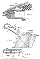
- FIG. 1 is an enlarged section illustrating the contact of the guard bar and blade upon the skin of a user of the shaving instrument of the invention;
- FIG. 2 is an enlarged section of the guard bar illustrating the texture thereon;
- FIG. 3 is an enlarged, partial cross-sectional view of the guard bar taken along
lines 3--3 of FIG. 2; and - FIG. 4 is a top view of the shaving instrument of the invention to illustrate the top cover and guard bar.
- The invention disclosed in this application is an improvement upon the applicant,s prior U.S. Patent 4,502,217, the disclosure of which is expressly incorporated herein by reference thereto specifically with regard to the position of the shaving head upon the shaving instrument, as well as to the attachment of the guard bar to the shaving head.
- Referring now to FIG. 1, there is illustrated a shaving
head 10 includingguard bar 12,razor blade 14,base member 16 andcover member 18. Razorblade 14 is firmly clamped betweenbase member 16 andcover 18 and cannot be exchanged. Thebase member 16 is firmly attached to a handle member, which is preferably made of a plastic material. - This
guard bar 12 is provided with what may be termed microstretch elements constituting recessedportions 22 as best illustrated in FIGS. 2 and 3, and raisedtextured mounds 24 as best illustrated in FIG. 3. Recessedportions 22 have narrow mounds on their boundaries and form a meander or wavy line as they extend across theexterior surface 25 of the guard bar for engagement with theskin 20 of the user of the shaving instrument. - These
grooves 22 and raisedmounds 24 are provided by a high energy beam, such as that of a laser or the like. The laser beam provides uniform, exactly reproducible groove and mound patterns upon the guard bar so long as suitable operating parameters are established and maintained, while the coined, stamped or embossed patterns, which have previously been provided as the roughened surface of the guard bars, were produced by tools subject to wear which results in non-uniform and uncontrolled textures. The textures obtained by chemical and/or abrasive treatments are also uncontrollable erosions. Such erosive removals of material from the surface of the bars are substantially dependent upon grain structure and may decrease, rather than increase, the desired friction upon the skin. - In the manufacturing sequence, a wire of approximately the same dimensions as disclosed in the applicant's earlier U.S. Patent 4,502,217 has its
end portions 26 bent at right angles thereto for initial orientation with respect to the laser beam and future positioning in the shavinghead 10. Thereafter, a series of adjacently aligned guard bars pass below a YAG-Nd laser. This laser is of the type which is conventionally used to scribe lines, text or alpha-numeric characters on steel or other metals. This laser is operated at a power output of between 30 and 60 watts and is focused to a beam of between 0.005 to 0.015 millimeters diameter so as to provide a groove width of about 50 to 150 microns and a depth of between about 3 and 8 microns below the original guard bar surface. The mounds outlining each groove consist of a resolidified portion of the material removed to create the groove, and have a height of between about 1 and 3 microns above the original surface, and a width of 3 to 10 microns. The topography of the textured mounds includes surface features forming millions of submicroscopic peaks per square millimeter which can be observed, for example, by a scanning tunneling microscope. The energy input from the laser beam should be such that the macroscopic shape of guard bars are not substantially deformed therefrom. - The relative speed of movement in the X and Y directions between the guard bars and the laser beam can be as desired to impart a meander configuration upon the surface of the bar. Speeds between about 10 and 200, and preferably between 40 and 100, millimeters per second, provide acceptable groove and mound configurations. Generally, the guard bars are moved relative to the laser beam in a slot or other fixture capable of orienting the desired portion of the guard bar exterior surface to the beam. The laser beam is oscillated in a Y-direction across the surface of the guard bar by a rocking motion of a mirror or other laser reflecting source, or by moving the guard bar in the Y direction as it passes under the laser beam, produces a 0.8 millimeter band in the Y-direction. Alternately, an imprint of the meander across a 60° arc of the guard bar surface can be used, as shown in FIG. 3.
- The energy of the laser beam causes a portion of the surface of the guard bar to be melted and vaporized to form the
groove 22, withside mounds 24 being formed by solidification of a part of this melted guard bar material. Themeander 22 is provided on the exterior surface of the guard bar in orientation for optimum contact with the skin of the user of the shaving instrument. If the line at which the guard bar outer surface is perpendicular to the razor blade is assumed to represent a twelve o'clock position, then the most preferred usable region of the guard bar outer surface would be a band spanning a 60 degree circumference ranging from 45 degrees on the counterclockwise side of the twelve o'clock position and to 15 degrees on the clockwise side, as shown in FIG. 3. However, depending upon the nature of the texture desired for imparting the appropriate surface friction and drag, themeander 22 can be placed on any region of the outer surface of the guard bar from a position of nine o'clock to and including two o'clock relative to the twelve o'clock position stated above, as shown in FIG. 1. - The width of the
groove 22 and the height of theside mounds 24 can be varied to provide different effects upon the skin of the user. While the focus of the laser beam normal to the surface of the guard bar results in a groove having substantially symmetrical mounds on each side, a variation of the incident angle of the beam, such as by applying the beam at a tangential direction, could result in a groove or depression having uneven or one sided mounds. - Instead of an
elongated groove 22 in the meander configuration, it is also possible to utilize the laser beam to make a plurality of discrete craters or dots upon the surface of the guard bar in the desired position with respect to the skin of the user. These dots can be round, oval or arcuate, discrete as mentioned above, or partially touching or overlaping each other. - It is also possible to use instead of a meander a plurality of straight lines each of which are formed by the
groove 22 and themound boundaries 24 as described above with regard to the meander. The importance of the use of the laser in forming these shapes or designs is that some of the material which is liquified by the laser beam forms the mounds, and that these mounds form a periphery or boundary on at least one side of the depression. Thus, after continuously applying or pulsing the beam, by varying the focus of or the current supplied to the beam, or by controlling the movement of the part relative to the beam, a wide variety of closely controlled shapes, configurations and textures can be obtained, all of which contemplated by the present invention. - Although the preferred material for the guard bar is currently stainless steel, it is conceivable that the bar can be made of other metals such as steel, aluminum, copper, nickel or metallic alloys. Also, it is possible to utilize engineering plastics which have a high stiffness and sufficient mechanical strength for providing the appropriate degree of friction and drag upon the skin of the user without the texture being changed during the useful life of the shaving instrument. Suitable plastics include the engineering thermoplastics and in particular, a new type material known as the aromatic polyester liquid crystal polymers. These liquid crystal polymers are sold by Dupont under the tradename HX 3000 High Temperature Thermoplastic Polyester Resins. In addition to the 3000 grade, it is also possible to use either the 2000 or 4000 grade, all with or without glass reinforcement. It is believed that glass or other reinforcement is not necessary to enhance the appropriate mechanical strength of the plastic material, but it may be advantageous to utilize such reinforcement in order to provide additional abrasion characteristics to the
groove 22 andmounds 24 to assist in providing the appropriate degree of tension, friction and drag upon the skin of the user. - As noted in applicant,s earlier patent, the distance between the texture surface of the guard bar and the razor blade should be maintained at between about 1 and 2 millimeters to allow for cut hair and skin lubricants (i.e. soap or shaving cream) to be removed while the blade is passing over the skin. This distance facilitates instant cleaning and removal of the hair and lubricants from the blade.
- Thus, it can be seen that, by use of the guard bar and shaving instrument according to the present invention, a formation of the skin surface which presents the hair properly to the cutting edge of blade is achieved. This skin is deformed by the pressure of the razor and guard bar against the face, plus the movement of the guard bar across the skin to extent that it causes a proper positioning of the skin at the point contacted by the blade. In addition, the guard bar provides a degree of drag or friction which causes the proper passage for what is termed, according to the invention of the Rodriques patent, the "flow" of skin from the guard bar to the cutting edge of the blade. This feature can now be achieved by the novel and uniformly controlled texture provided by the present invention.
- The invention is applicable to various forms of shaving instruments but has been illustrated as applicable to a disposable unit having a single edge flat blade on a platform. However, the invention should not be limited beyond the true spirit and scope of the appended claims as interpreted by those skilled in the art having this specification before them.
Claims (25)
Applications Claiming Priority (2)
| Application Number | Priority Date | Filing Date | Title |
|---|---|---|---|
| US07/348,630 US4998347A (en) | 1989-05-08 | 1989-05-08 | Shaving instrument with high energy beam induced microstretch element |
| US348630 | 1994-12-02 |
Publications (3)
| Publication Number | Publication Date |
|---|---|
| EP0397638A2 true EP0397638A2 (en) | 1990-11-14 |
| EP0397638A3 EP0397638A3 (en) | 1991-07-24 |
| EP0397638B1 EP0397638B1 (en) | 1994-06-15 |
Family
ID=23368862
Family Applications (1)
| Application Number | Title | Priority Date | Filing Date |
|---|---|---|---|
| EP90890094A Expired - Lifetime EP0397638B1 (en) | 1989-05-08 | 1990-03-30 | Shaving instrument with high energy beam induced microstretch element |
Country Status (6)
| Country | Link |
|---|---|
| US (1) | US4998347A (en) |
| EP (1) | EP0397638B1 (en) |
| AT (1) | ATE107218T1 (en) |
| CA (1) | CA2014883C (en) |
| DE (1) | DE69009858T2 (en) |
| ES (1) | ES2058882T3 (en) |
Cited By (6)
| Publication number | Priority date | Publication date | Assignee | Title |
|---|---|---|---|---|
| WO1996035558A1 (en) * | 1995-05-08 | 1996-11-14 | Warner-Lambert Company | Shaving implement |
| EP0761393A2 (en) * | 1995-07-26 | 1997-03-12 | Friedrich SCHÄCHTER | Device for conditioning hairy skin before shaving |
| WO1997025190A1 (en) * | 1996-01-12 | 1997-07-17 | The Gillette Company | Razor blade unit |
| WO1997033729A1 (en) * | 1996-03-11 | 1997-09-18 | The Gillette Company | Safety razors |
| US6298557B1 (en) | 1996-03-11 | 2001-10-09 | The Gillette Company | Safety razors |
| US6516518B1 (en) | 1996-01-12 | 2003-02-11 | The Gillette Company | Razor blade unit |
Families Citing this family (30)
| Publication number | Priority date | Publication date | Assignee | Title |
|---|---|---|---|---|
| GB9022128D0 (en) * | 1990-10-11 | 1990-11-21 | Gillette Co | Safety razors |
| IL97531A (en) * | 1991-03-12 | 1995-12-31 | Kelman Elliot | Hair cutting apparatus |
| US5402697A (en) * | 1993-11-18 | 1995-04-04 | Brooks; Shirley E. | Depilatory applicating razor |
| US6041503A (en) * | 1998-02-25 | 2000-03-28 | Calwell; Stuart | Aroma therapy delivery system |
| US6681665B2 (en) * | 1998-02-25 | 2004-01-27 | Stuart Calwell | Aroma therapy delivery system |
| US6131287A (en) * | 1998-06-08 | 2000-10-17 | American Safety Razor Company | Razor cartridge with dimpled blade guard |
| US20040194316A1 (en) * | 2003-04-04 | 2004-10-07 | Ray-Ming Lin | Shaver having germ-killing device |
| JP2007515190A (en) * | 2003-12-12 | 2007-06-14 | ビック−ヴァイオレックス ソシエテ アノニム | Improved method of manufacturing a wet shaving device with a protective bar |
| US20050188539A1 (en) * | 2004-02-26 | 2005-09-01 | Prudden John Jr. | Shaving blade unit |
| US20050235495A1 (en) * | 2004-04-22 | 2005-10-27 | Aviza Gregory D | Shaving systems with exfoliation |
| ATE501819T1 (en) * | 2004-10-05 | 2011-04-15 | Eveready Battery Inc | RAZOR |
| US7827894B2 (en) * | 2005-02-23 | 2010-11-09 | Feather Safety Razor Co., Ltd. | Microtome blade |
| US20060218794A1 (en) * | 2005-04-05 | 2006-10-05 | Eveready Battery Company, Inc. | Razor cartridge |
| US20070227008A1 (en) * | 2006-03-29 | 2007-10-04 | Andrew Zhuk | Razors |
| US7448135B2 (en) * | 2006-03-29 | 2008-11-11 | The Gillette Company | Multi-blade razors |
| US7882640B2 (en) * | 2006-03-29 | 2011-02-08 | The Gillette Company | Razor blades and razors |
| US8499462B2 (en) | 2006-04-10 | 2013-08-06 | The Gillette Company | Cutting members for shaving razors |
| US8011104B2 (en) | 2006-04-10 | 2011-09-06 | The Gillette Company | Cutting members for shaving razors |
| JP4796646B2 (en) * | 2007-04-20 | 2011-10-19 | フェザー安全剃刀株式会社 | Replacement blade and curl suppression plate for microtome |
| US20090071006A1 (en) * | 2007-09-14 | 2009-03-19 | The Gillette Company | Safety razor with enhanced shaving aid member |
| US20090071007A1 (en) * | 2007-09-14 | 2009-03-19 | The Gillette Company | Safety razor with enhanced shaving aid member having protuberances |
| KR20110011630A (en) * | 2008-05-23 | 2011-02-08 | 더 질레트 컴퍼니 | Razor comprising a three dimensional, microstructured abrasion material |
| US9248579B2 (en) * | 2008-07-16 | 2016-02-02 | The Gillette Company | Razors and razor cartridges |
| US9221185B2 (en) * | 2008-09-10 | 2015-12-29 | The Gillette Company | Shaving razors and cartridges |
| US8209867B2 (en) * | 2008-10-02 | 2012-07-03 | The Gillette Company | Shaving razors and cartridges |
| US8782903B2 (en) * | 2009-05-29 | 2014-07-22 | The Gillette Company | Shaving razor comb guard for a trimming blade |
| US8726518B2 (en) * | 2010-03-16 | 2014-05-20 | The Gillette Company | Shaving razors and cartridges |
| US8448339B2 (en) * | 2010-08-03 | 2013-05-28 | The Gillette Company | Shaving cartridge with supressed blade geometry |
| US8413334B2 (en) * | 2010-08-03 | 2013-04-09 | The Gillette Company | Shaving cartridge guard for supporting skin |
| US9492933B2 (en) | 2011-09-30 | 2016-11-15 | The Gillette Company | Guard for a shaving razor |
Citations (4)
| Publication number | Priority date | Publication date | Assignee | Title |
|---|---|---|---|---|
| US2048565A (en) * | 1932-11-29 | 1936-07-21 | Magazine Repeating Razor Co | Razor |
| US3138865A (en) * | 1960-08-13 | 1964-06-30 | Meyer Eugen | Safety razor having skin-stretching and guiding means |
| US3626143A (en) * | 1969-04-02 | 1971-12-07 | American Can Co | Scoring of materials with laser energy |
| US4502217A (en) * | 1980-04-10 | 1985-03-05 | Schaechter Friedrich | Shaving instrument |
Family Cites Families (4)
| Publication number | Priority date | Publication date | Assignee | Title |
|---|---|---|---|---|
| US2349252A (en) * | 1943-08-18 | 1944-05-23 | Edward R Douglass | Combined knife and razor |
| US3172202A (en) * | 1963-09-19 | 1965-03-09 | Claude W Sooter | Protective cover for safety razor |
| US3399455A (en) * | 1967-07-13 | 1968-09-03 | Steere Entpr Inc | Seamless plastic razor head cover |
| US3786563A (en) * | 1971-08-31 | 1974-01-22 | Gillette Co | Shaving system |
-
1989
- 1989-05-08 US US07/348,630 patent/US4998347A/en not_active Expired - Lifetime
-
1990
- 1990-03-30 ES ES90890094T patent/ES2058882T3/en not_active Expired - Lifetime
- 1990-03-30 AT AT90890094T patent/ATE107218T1/en not_active IP Right Cessation
- 1990-03-30 DE DE69009858T patent/DE69009858T2/en not_active Expired - Lifetime
- 1990-03-30 EP EP90890094A patent/EP0397638B1/en not_active Expired - Lifetime
- 1990-04-19 CA CA002014883A patent/CA2014883C/en not_active Expired - Lifetime
Patent Citations (4)
| Publication number | Priority date | Publication date | Assignee | Title |
|---|---|---|---|---|
| US2048565A (en) * | 1932-11-29 | 1936-07-21 | Magazine Repeating Razor Co | Razor |
| US3138865A (en) * | 1960-08-13 | 1964-06-30 | Meyer Eugen | Safety razor having skin-stretching and guiding means |
| US3626143A (en) * | 1969-04-02 | 1971-12-07 | American Can Co | Scoring of materials with laser energy |
| US4502217A (en) * | 1980-04-10 | 1985-03-05 | Schaechter Friedrich | Shaving instrument |
Cited By (8)
| Publication number | Priority date | Publication date | Assignee | Title |
|---|---|---|---|---|
| WO1996035558A1 (en) * | 1995-05-08 | 1996-11-14 | Warner-Lambert Company | Shaving implement |
| US5689883A (en) * | 1995-05-08 | 1997-11-25 | Warner-Lambert Company | Shaving implement |
| EP0761393A2 (en) * | 1995-07-26 | 1997-03-12 | Friedrich SCHÄCHTER | Device for conditioning hairy skin before shaving |
| EP0761393A3 (en) * | 1995-07-26 | 1999-01-20 | Friedrich SCHÄCHTER | Device for conditioning hairy skin before shaving |
| WO1997025190A1 (en) * | 1996-01-12 | 1997-07-17 | The Gillette Company | Razor blade unit |
| US6516518B1 (en) | 1996-01-12 | 2003-02-11 | The Gillette Company | Razor blade unit |
| WO1997033729A1 (en) * | 1996-03-11 | 1997-09-18 | The Gillette Company | Safety razors |
| US6298557B1 (en) | 1996-03-11 | 2001-10-09 | The Gillette Company | Safety razors |
Also Published As
| Publication number | Publication date |
|---|---|
| EP0397638A3 (en) | 1991-07-24 |
| DE69009858T2 (en) | 1995-01-05 |
| ATE107218T1 (en) | 1994-07-15 |
| DE69009858D1 (en) | 1994-07-21 |
| ES2058882T3 (en) | 1994-11-01 |
| EP0397638B1 (en) | 1994-06-15 |
| CA2014883A1 (en) | 1990-11-08 |
| CA2014883C (en) | 1999-10-19 |
| US4998347A (en) | 1991-03-12 |
Similar Documents
| Publication | Publication Date | Title |
|---|---|---|
| EP0397638B1 (en) | Shaving instrument with high energy beam induced microstretch element | |
| EP3854546B1 (en) | Electric beard trimmer | |
| JP6392992B2 (en) | Dry shaver | |
| JP3860297B2 (en) | Hair clipper for cutting hair | |
| RU2119424C1 (en) | Device for shaving, method and device for manufacture of razor blade | |
| EP0521086B1 (en) | Safety razor | |
| WO2009095198A1 (en) | Trimmer comb, hair trimmer comprising a trimmer comb and method of manufacturing a trimmer comb | |
| US20090025228A1 (en) | Inner cutter with cutter blades at different radii, method for manufacturing such unit, shaver head and rotary shaver provided therewith | |
| KR20040002958A (en) | Razor blade | |
| JP2006524104A (en) | Razor blade having non-linear cutting edge and manufacturing method thereof | |
| WO1999014019A1 (en) | Improved long hair cutting and beard lifting foil construction | |
| JP2008023122A (en) | Cutter for electric razor | |
| US20090038166A1 (en) | Sharp undercutter and undercutter fabrication | |
| US10583574B2 (en) | Integrated shaving mechanism | |
| JP3454619B2 (en) | Electric razor | |
| JP2002001693A (en) | Sheet/cord type material and cutting device for it | |
| JP2006509588A (en) | Gradual hair surface | |
| JP2001113066A (en) | Spare blade with round rugged single edge | |
| GB2286984A (en) | Reciprocatory dry shaver |
Legal Events
| Date | Code | Title | Description |
|---|---|---|---|
| PUAI | Public reference made under article 153(3) epc to a published international application that has entered the european phase |
Free format text: ORIGINAL CODE: 0009012 |
|
| AK | Designated contracting states |
Kind code of ref document: A2 Designated state(s): AT DE ES FR GB GR IT SE |
|
| PUAL | Search report despatched |
Free format text: ORIGINAL CODE: 0009013 |
|
| AK | Designated contracting states |
Kind code of ref document: A3 Designated state(s): AT DE ES FR GB GR IT SE |
|
| 17P | Request for examination filed |
Effective date: 19910911 |
|
| 17Q | First examination report despatched |
Effective date: 19911219 |
|
| GRAA | (expected) grant |
Free format text: ORIGINAL CODE: 0009210 |
|
| AK | Designated contracting states |
Kind code of ref document: B1 Designated state(s): AT DE ES FR GB GR IT SE |
|
| REF | Corresponds to: |
Ref document number: 107218 Country of ref document: AT Date of ref document: 19940715 Kind code of ref document: T |
|
| RAP2 | Party data changed (patent owner data changed or rights of a patent transferred) |
Owner name: BIC |
|
| RIN2 | Information on inventor provided after grant (corrected) |
Free format text: SCHAECHTER, FRIEDRICH |
|
| REF | Corresponds to: |
Ref document number: 69009858 Country of ref document: DE Date of ref document: 19940721 |
|
| ET | Fr: translation filed | ||
| ITF | It: translation for a ep patent filed | ||
| REG | Reference to a national code |
Ref country code: ES Ref legal event code: FG2A Ref document number: 2058882 Country of ref document: ES Kind code of ref document: T3 |
|
| REG | Reference to a national code |
Ref country code: GR Ref legal event code: FG4A Free format text: 3013145 |
|
| EAL | Se: european patent in force in sweden |
Ref document number: 90890094.7 |
|
| PLBE | No opposition filed within time limit |
Free format text: ORIGINAL CODE: 0009261 |
|
| STAA | Information on the status of an ep patent application or granted ep patent |
Free format text: STATUS: NO OPPOSITION FILED WITHIN TIME LIMIT |
|
| 26N | No opposition filed | ||
| REG | Reference to a national code |
Ref country code: GB Ref legal event code: IF02 |
|
| PGFP | Annual fee paid to national office [announced via postgrant information from national office to epo] |
Ref country code: SE Payment date: 20040330 Year of fee payment: 15 |
|
| PG25 | Lapsed in a contracting state [announced via postgrant information from national office to epo] |
Ref country code: SE Free format text: LAPSE BECAUSE OF NON-PAYMENT OF DUE FEES Effective date: 20050331 |
|
| EUG | Se: european patent has lapsed | ||
| PGFP | Annual fee paid to national office [announced via postgrant information from national office to epo] |
Ref country code: IT Payment date: 20060331 Year of fee payment: 17 |
|
| PGFP | Annual fee paid to national office [announced via postgrant information from national office to epo] |
Ref country code: AT Payment date: 20090304 Year of fee payment: 20 Ref country code: ES Payment date: 20090326 Year of fee payment: 20 |
|
| PGFP | Annual fee paid to national office [announced via postgrant information from national office to epo] |
Ref country code: GR Payment date: 20090330 Year of fee payment: 20 |
|
| PGFP | Annual fee paid to national office [announced via postgrant information from national office to epo] |
Ref country code: DE Payment date: 20090327 Year of fee payment: 20 |
|
| PG25 | Lapsed in a contracting state [announced via postgrant information from national office to epo] |
Ref country code: IT Free format text: LAPSE BECAUSE OF NON-PAYMENT OF DUE FEES Effective date: 20070330 |
|
| PGFP | Annual fee paid to national office [announced via postgrant information from national office to epo] |
Ref country code: FR Payment date: 20090317 Year of fee payment: 20 |
|
| PGFP | Annual fee paid to national office [announced via postgrant information from national office to epo] |
Ref country code: GB Payment date: 20090403 Year of fee payment: 20 |
|
| REG | Reference to a national code |
Ref country code: GB Ref legal event code: PE20 Expiry date: 20100329 |
|
| REG | Reference to a national code |
Ref country code: ES Ref legal event code: FD2A Effective date: 20100331 |
|
| PG25 | Lapsed in a contracting state [announced via postgrant information from national office to epo] |
Ref country code: GB Free format text: LAPSE BECAUSE OF EXPIRATION OF PROTECTION Effective date: 20100329 |
|
| PG25 | Lapsed in a contracting state [announced via postgrant information from national office to epo] |
Ref country code: ES Free format text: LAPSE BECAUSE OF EXPIRATION OF PROTECTION Effective date: 20100331 |
|
| PG25 | Lapsed in a contracting state [announced via postgrant information from national office to epo] |
Ref country code: DE Free format text: LAPSE BECAUSE OF EXPIRATION OF PROTECTION Effective date: 20100330 |