EP0397274B1 - Mastitis detector for diary cattle - Google Patents
Mastitis detector for diary cattle Download PDFInfo
- Publication number
- EP0397274B1 EP0397274B1 EP90201176A EP90201176A EP0397274B1 EP 0397274 B1 EP0397274 B1 EP 0397274B1 EP 90201176 A EP90201176 A EP 90201176A EP 90201176 A EP90201176 A EP 90201176A EP 0397274 B1 EP0397274 B1 EP 0397274B1
- Authority
- EP
- European Patent Office
- Prior art keywords
- milk
- measuring chamber
- electrodes
- detector
- mastitis
- Prior art date
- Legal status (The legal status is an assumption and is not a legal conclusion. Google has not performed a legal analysis and makes no representation as to the accuracy of the status listed.)
- Expired - Lifetime
Links
Images

Classifications
-
- A—HUMAN NECESSITIES
- A01—AGRICULTURE; FORESTRY; ANIMAL HUSBANDRY; HUNTING; TRAPPING; FISHING
- A01J—MANUFACTURE OF DAIRY PRODUCTS
- A01J5/00—Milking machines or devices
- A01J5/013—On-site detection of mastitis in milk
- A01J5/0136—On-site detection of mastitis in milk by using milk flow characteristics, e.g. differences between udder quarters or differences with previous milking runs
-
- A—HUMAN NECESSITIES
- A01—AGRICULTURE; FORESTRY; ANIMAL HUSBANDRY; HUNTING; TRAPPING; FISHING
- A01J—MANUFACTURE OF DAIRY PRODUCTS
- A01J5/00—Milking machines or devices
- A01J5/013—On-site detection of mastitis in milk
- A01J5/0133—On-site detection of mastitis in milk by using electricity, e.g. conductivity or capacitance
-
- G—PHYSICS
- G01—MEASURING; TESTING
- G01N—INVESTIGATING OR ANALYSING MATERIALS BY DETERMINING THEIR CHEMICAL OR PHYSICAL PROPERTIES
- G01N33/00—Investigating or analysing materials by specific methods not covered by groups G01N1/00 - G01N31/00
- G01N33/02—Food
- G01N33/04—Dairy products
Definitions
- This invention relates to a mastitis detector of the throughflow type, comprising an inlet stub and an outlet stub by means of which the mastitis detector can be coupled with a milk tube; a measuring chamber having side walls, a closed bottom, and an opening opposite said bottom in spaced relationship to said inlet stub, through which opening the milk to be monitored, supplied through the inlet stub, can flow into the measuring chamber, and through which the milk can again leave the measuring chamber when the level of the milk within the measuring chamber exceeds the height of the lowest side wall portion; and a pair of electrodes in the bottom of said measuring chamber for measuring the electrical conductivity of the milk.
- a similar detector is disclosed in German Offenlegungsschrift 3,308,361.
- One advantage of the throughflow type of mastitis detector is that such a detector can be permanently mounted in the milk tube of a milking machine, so that the milk can be checked automatically and directly each time a cow is milked, without it being necessary for separate samples to be taken, which should then be examined later and often elsewhere.
- a throughflow detector lends itself particularly well for being permanently mounted in the short milk tubes, i.e., in the milk tubes between the milk claw and the teat cups. If a throughflow type of mastitits detector is provided in each of the short milk tubes, an incipient mastitis can be most rapidly detected, and in addition it can be directly detected in which part of the udder the inflammation occurs.
- German Offenlegungsschrift 3.308.361 One disadvantage of the mastitis detector disclosed in German Offenlegungsschrift 3.308.361 is that it has electrodes which are electrically spaced very closely together. Consequently, when this detector is used for measuring the conductivity of the milk in the measuring chamber, only a short measuring path through the milk is available. As a consequence, spurious factors, such as the transition resistance between the electrodes and the milk have a relatively great influence on the result of the measurement. Indeed, the accuracy of a conductivity measurement of the milk in the measuring chamber using the known throughflow meter leaves something to be desired. By way of an alternative, the known detector could be equipped with a much wider measuring chamber, but this gives the detector a bulky size, which is undesirable.
- Another disadvantage of the known throughflow detector is that a gap can be formed along the circumference of the electrodes, as a result of the electrodes and the plastic material of the bottom having different coefficients of thermal expansion. Such gaps are difficult to clean, and there is the danger that a bacterial colony develops in such gaps.
- the present invention provides a mastitis detector as defined in the opening paragraph of this specification, which is characterized in that at least one of the electrodes has a convex head projecting above the bottom surface and a shank extending through an opening in the bottom.
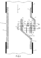
- Fig. 1 shows diagrammatically and in longitudinal sectional view an example of a mastitis detector 1 according to the present invention.
- the detector comprises a housing or body 2 with an inlet stub 3 and an outlet stub 4, with which the body can be mounted in a milk tube 5.
- the direction of the milk stream is indicated by an arrow 6.
- the housing or body is made of an electrically insulating material, for example, a suitable synthetic plastics.
- a measuring chamber 7 Formed in body 1 is a measuring chamber 7, which is laterally off-set relative to the longitudinal axis of the inlet stub.
- the measuring chamber has a closed bottom 8, and side walls 9 and 10, partly merging with the wall of the inlet stub and partly with the wall of the outlet stub.
- the side walls are formed so as to provide a lowered portion 11 through which milk collected by the measuring chamber may flow out of the chamber.
- a minimum level of milk is maintained in the measuring chamber, defined by the height of the lowered portion relative to bottom 8.
- the measuring chamber forms, as it were, a cup provided against the inner wall of body 2, whose opening faces the inlet stub.
- the electrodes are each approximately mushroom-shaped with a convex head 14, 15, projecting above the surface of bottom 8 of the measuring chamber, and a shank 16, 17 extending through an opening in the bottom.
- the electrodes are preferably made of stainless steel and are preferably hollow with thin walls. Furthermore, the electrodes are preferably finished smooth on the outside, so as to prevent fouling. Owing to the convex shape, a relatively large contacting surface is presented to the milk supplied to the measuring chamber, which, like the smooth finish, promotes effective electrical contact with the milk.
- the electrodes are provided with connecting wires 18, 19, which in the example shown are attached to the shanks 16, 17.
- the shanks extend through bottom 8 into a mass 20 of electrically and thermally insulating material, for example, epoxy resin.
- a partition 21 serving to lengthen the measuring path between the electrodes. The effect of any transition resistance between the electrodes and the milk during the measurement of the conductivity of the milk is thus still further reduced.
- the measuring chamber may be relatively small, and accordingly, the entire mastitis detector may be of small design.
- a mastitis detector according to the present invention is thus highly suitable for being permanently mounted in the milk tubes.
- the shank of an electrode has a smaller diameter than the convex part.
- This provides a shoulder 22, by which the convex part rests on the bottom 8 of the measuring chamber, and with a suitable construction of the shank can be pulled with some force into contact with the bottom 8. If desired, the shoulder may be somewhat undercut. Any gap which may be formed during use between the shank and the bore in the bottom in which the shank is placed will then remain inaccessible to the milk in the measuring chamber, so that no fouling can take place in such a gap.
- a temperature sensor 23 is provided in one of the electrodes, which can be done without any problems owing to the convex and hollow shape of the electrodes.
- the temperature sensor has connecting wires 24 and may be a temperature-sensitive resistor, such as an MTC resistor.
- the temperature sensor is preferably brought into proper thermal contact with the electrode concerned by means of known per se heat-conductive paste.
- the convex electrode shape and the thin wall of the electrodes promote a good thermal contact with the milk, so that an accurate measurement of the temperature is possible.
- mastitis leads to an increase in temperature of the milk, a highly reliable mastitis detection can be realized by comparing the result of the conductivity measurement with the result of the temperature measurement.
- the design of the mastitis detector shown is such that it can be cleaned in a simple manner. By reversing the detector or the tube or milk claw mounting the detector, all residual milk or cleaning fluid will flow out of the detector.
- the operation of the mastitis detector is as follows.
- the mastitis detector When the mastitis detector is placed in the milking system, it should be so positioned that the milk flows over the electrodes in the measuring chamber. Furthermore, it is of importance that the milk does not experience undue resistance from the mastitis detector and its housing.
- the milk, or a representative part thereof is supplied to the detector in a space specially provided for the purpose, formed by the housing, periodical measurements of the electrical conductivity and temperature of the milk start.
- the results of the measurements can be processed in a process computer which compares the results of the measurements with the history of the conductivity and the temperature of the milk and provides an attention signal when substantial differences are detected.
- Mastitis can be detected in a simple manner at any desired point in the milking system by means of the detector according to the present invention. It is recommendable, however, for the mastitis detector to be mounted in a milk claw or in a milk tube of a milking system, and this preferably one detector for the milk stream of each individual teat.
- An important advantage of measuring per teat, and hence per (udder) quarter is that the alterations in conductivity can be measured more clearly than after the milk from the four quarters has been mixed. The fact is that mastitis virtually always arises in one of the quarters. Moreover, if desired, any contaminated milk can be separately discharged per quarter through an electrically operated valve.
- a temperature sensor may be placed in both electrodes.
- the partition may be formed with a broadened upper edge to increase the measuring path still further.
- the electrodes may have a threaded shank, so that they may be mounted by means of a nut screwed on the shank against the bottom surface of bottom 8.
- the electrodes may, for example, be provided with a solid thinner central shank.
- the measuring chamber provided with electrodes and partition, as described above, may be made as a loose unit, and then mounted, for example, in the milk claw or any other part of a milking system.
- a loose measuring chamber unit is shown diagrammatically in the accompanying Fig. 4.
Landscapes
- Life Sciences & Earth Sciences (AREA)
- Animal Husbandry (AREA)
- Environmental Sciences (AREA)
- Engineering & Computer Science (AREA)
- Food Science & Technology (AREA)
- Health & Medical Sciences (AREA)
- Chemical & Material Sciences (AREA)
- Physics & Mathematics (AREA)
- Medicinal Chemistry (AREA)
- Analytical Chemistry (AREA)
- Biochemistry (AREA)
- General Health & Medical Sciences (AREA)
- General Physics & Mathematics (AREA)
- Immunology (AREA)
- Pathology (AREA)
- Investigating Or Analyzing Materials By The Use Of Electric Means (AREA)
- Feed For Specific Animals (AREA)
- Investigating Or Analysing Biological Materials (AREA)
- Dairy Products (AREA)
Abstract
Description
- This invention relates to a mastitis detector of the throughflow type, comprising an inlet stub and an outlet stub by means of which the mastitis detector can be coupled with a milk tube; a measuring chamber having side walls, a closed bottom, and an opening opposite said bottom in spaced relationship to said inlet stub, through which opening the milk to be monitored, supplied through the inlet stub, can flow into the measuring chamber, and through which the milk can again leave the measuring chamber when the level of the milk within the measuring chamber exceeds the height of the lowest side wall portion; and a pair of electrodes in the bottom of said measuring chamber for measuring the electrical conductivity of the milk.
- A similar detector is disclosed in German Offenlegungsschrift 3,308,361. One advantage of the throughflow type of mastitis detector is that such a detector can be permanently mounted in the milk tube of a milking machine, so that the milk can be checked automatically and directly each time a cow is milked, without it being necessary for separate samples to be taken, which should then be examined later and often elsewhere. In addition, a throughflow detector lends itself particularly well for being permanently mounted in the short milk tubes, i.e., in the milk tubes between the milk claw and the teat cups. If a throughflow type of mastitits detector is provided in each of the short milk tubes, an incipient mastitis can be most rapidly detected, and in addition it can be directly detected in which part of the udder the inflammation occurs. This also creates the possibility for the milk from the affected part of the udder to be discharged to a separate container through a controllable valve in the short milk tube and/or the milk claw, provided for the purpose. The milk from the other parts of the udder, which at that moment is still excellently fit for human consumption, can be collected and processed further in the usual way..
- It is known that both clinical and subclinical mastitis infections in milk cattle can be diagnosed, among other means, on the ground of the altered pattern in the electrical conductivity of the milk which, in the case of a mastitis infection is substantially increased in a characteristic way. During the milking process of, for example, a cow, the variation of the conductivity of the milk is recorded per quarter - i.e., the part of a cow's udder drained by one teat. From the history of the conductivity, it can be derived whether it is substantially increased at a particular moment. The electrical conductivity can be measured, for example, by means of electrodes between which an A.C. voltage prevails. Such a method is known from Netherlands patent application No. 83,01231.
- One disadvantage of the mastitis detector disclosed in German Offenlegungsschrift 3.308.361 is that it has electrodes which are electrically spaced very closely together. Consequently, when this detector is used for measuring the conductivity of the milk in the measuring chamber, only a short measuring path through the milk is available. As a consequence, spurious factors, such as the transition resistance between the electrodes and the milk have a relatively great influence on the result of the measurement. Indeed, the accuracy of a conductivity measurement of the milk in the measuring chamber using the known throughflow meter leaves something to be desired. By way of an alternative, the known detector could be equipped with a much wider measuring chamber, but this gives the detector a bulky size, which is undesirable.
- Another disadvantage of the known throughflow detector is that a gap can be formed along the circumference of the electrodes, as a result of the electrodes and the plastic material of the bottom having different coefficients of thermal expansion. Such gaps are difficult to clean, and there is the danger that a bacterial colony develops in such gaps.
- It is an object of the present invention to overcome the disadvantages outlined above and, quite generally, to provide a reliable mastitis detector of the throughflow type.
- For this purpose, the present invention provides a mastitis detector as defined in the opening paragraph of this specification, which is characterized in that at least one of the electrodes has a convex head projecting above the bottom surface and a shank extending through an opening in the bottom.
- One embodiment of the invention will now be described, by way of example, with reference to the accompanying diagrammatic drawings. In said drawings,
- Fig. 1 shows a longitudinal sectional view of one embodiment of a mastitis detector according to the present invention;
- Fig. 2 shows a cross-sectional view, taken on the line II-II of Fig. 1; and
- Fig. 3 shows a cross-sectional view, taken on the line III-III of Fig. 1; and
- Fig. 4 shows a loose measuring chamber unit for a mastitis detector according to the present invention.
- Fig. 1 shows diagrammatically and in longitudinal sectional view an example of a mastitis detector 1 according to the present invention. The detector comprises a housing or
body 2 with aninlet stub 3 and anoutlet stub 4, with which the body can be mounted in amilk tube 5. The direction of the milk stream is indicated by anarrow 6. The housing or body is made of an electrically insulating material, for example, a suitable synthetic plastics. - Formed in body 1 is a
measuring chamber 7, which is laterally off-set relative to the longitudinal axis of the inlet stub. The measuring chamber has a closed bottom 8, andside walls - The measuring chamber forms, as it were, a cup provided against the inner wall of
body 2, whose opening faces the inlet stub. - Provided in the bottom of the measuring chamber are two
electrodes convex head shank - The electrodes are provided with connecting
wires shanks mass 20 of electrically and thermally insulating material, for example, epoxy resin. - Provided in the measuring chamber between
electrodes partition 21, serving to lengthen the measuring path between the electrodes. The effect of any transition resistance between the electrodes and the milk during the measurement of the conductivity of the milk is thus still further reduced. - By virtue of the use of the convex electrodes and the partition, the measuring chamber may be relatively small, and accordingly, the entire mastitis detector may be of small design. A mastitis detector according to the present invention is thus highly suitable for being permanently mounted in the milk tubes.
- In the embodiment shown, the shank of an electrode has a smaller diameter than the convex part. This provides a
shoulder 22, by which the convex part rests on the bottom 8 of the measuring chamber, and with a suitable construction of the shank can be pulled with some force into contact with the bottom 8. If desired, the shoulder may be somewhat undercut. Any gap which may be formed during use between the shank and the bore in the bottom in which the shank is placed will then remain inaccessible to the milk in the measuring chamber, so that no fouling can take place in such a gap. - Furthermore, in the embodiment shown, a
temperature sensor 23 is provided in one of the electrodes, which can be done without any problems owing to the convex and hollow shape of the electrodes. The temperature sensor has connectingwires 24 and may be a temperature-sensitive resistor, such as an MTC resistor. The temperature sensor is preferably brought into proper thermal contact with the electrode concerned by means of known per se heat-conductive paste. The convex electrode shape and the thin wall of the electrodes promote a good thermal contact with the milk, so that an accurate measurement of the temperature is possible. As mastitis leads to an increase in temperature of the milk, a highly reliable mastitis detection can be realized by comparing the result of the conductivity measurement with the result of the temperature measurement. - The design of the mastitis detector shown is such that it can be cleaned in a simple manner. By reversing the detector or the tube or milk claw mounting the detector, all residual milk or cleaning fluid will flow out of the detector.
- The operation of the mastitis detector is as follows. When the mastitis detector is placed in the milking system, it should be so positioned that the milk flows over the electrodes in the measuring chamber. Furthermore, it is of importance that the milk does not experience undue resistance from the mastitis detector and its housing. When the milk, or a representative part thereof, is supplied to the detector in a space specially provided for the purpose, formed by the housing, periodical measurements of the electrical conductivity and temperature of the milk start. The results of the measurements can be processed in a process computer which compares the results of the measurements with the history of the conductivity and the temperature of the milk and provides an attention signal when substantial differences are detected. Mastitis can be detected in a simple manner at any desired point in the milking system by means of the detector according to the present invention. It is recommendable, however, for the mastitis detector to be mounted in a milk claw or in a milk tube of a milking system, and this preferably one detector for the milk stream of each individual teat. An important advantage of measuring per teat, and hence per (udder) quarter is that the alterations in conductivity can be measured more clearly than after the milk from the four quarters has been mixed. The fact is that mastitis virtually always arises in one of the quarters. Moreover, if desired, any contaminated milk can be separately discharged per quarter through an electrically operated valve.
- It is observed that, after reading the foregoing, various modifications will readily occur to one skilled in the art. Thus, if desired, a temperature sensor may be placed in both electrodes. Also, the partition may be formed with a broadened upper edge to increase the measuring path still further. The electrodes may have a threaded shank, so that they may be mounted by means of a nut screwed on the shank against the bottom surface of bottom 8. Also the electrodes may, for example, be provided with a solid thinner central shank.
- It is further observed that the measuring chamber, provided with electrodes and partition, as described above, may be made as a loose unit, and then mounted, for example, in the milk claw or any other part of a milking system. One embodiment of such a loose measuring chamber unit is shown diagrammatically in the accompanying Fig. 4.
Claims (9)
- A throughflow-type mastitis detector comprising an inlet stub (3) and an outlet stub (4) by means of which the mastitis detector can be coupled to a milk tube (5); a measuring chamber (7) having side walls (9,10), a closed bottom (8), and an opening opposite said bottom in spaced relationship to said inlet stub, through which opening the milk to be monitored, supplied through the inlet stub, can flow into the measuring chamber, and through which the milk can again leave the measuring chamber when the level of the milk within the measuring chamber exceeds the height of the lowest side wall portion; and a pair of electrodes (12,13) in the bottom of said measuring chamber for measuring the electrical conductivity of the milk, characterized in that at least one of the electrodes has a convex head (14,15) projecting above the bottom surface and a shank (16,17) extending through an opening in the bottom.
- A mastitis detector as claimed in claim 1, characterized in that the convex head has a larger diameter than the shank and presents a shoulder portion resting on the chamber bottom.
- A mastitis detector as claimed in claim 1 or 2, characterized in that the convex head is hollow.
- A mastitis detector as claimed in any of the preceding claims, characterized by a partition (21) formed on the bottom of the measuring chamber between the electrodes, said partition being lower than the lowest side wall portion.
- A mastitis detector as claimed in claim 3, characterized in that the convex head has a thin wall.
- A mastitis detector as claimed in any of the preceding claims, characterized in that the heads of the electrodes are finished smooth.
- A mastitis detector as claimed in any of claims 3-6, characterized by a temperature sensor (23) provided in the hollow convex head of at least one of the electrodes.
- A measuring chamber unit for mastitis detection, comprising a measuring chamber (7) with side walls (9,10), a closed bottom (8), and an open top, and two electrodes (12,13) mounted in said bottom, characterized in that at least one of the electrodes is formed and designed as defined in any of claims 1-3 or 5-7.
- A unit as claimed in claim 8, characterized by a partition formed on the bottom of the measuring chamber between the electrodes.
Applications Claiming Priority (2)
| Application Number | Priority Date | Filing Date | Title |
|---|---|---|---|
| NL8901165A NL8901165A (en) | 1989-05-10 | 1989-05-10 | MASTITIS SENSOR. |
| NL8901165 | 1989-05-10 |
Publications (2)
| Publication Number | Publication Date |
|---|---|
| EP0397274A1 EP0397274A1 (en) | 1990-11-14 |
| EP0397274B1 true EP0397274B1 (en) | 1994-02-16 |
Family
ID=19854620
Family Applications (1)
| Application Number | Title | Priority Date | Filing Date |
|---|---|---|---|
| EP90201176A Expired - Lifetime EP0397274B1 (en) | 1989-05-10 | 1990-05-09 | Mastitis detector for diary cattle |
Country Status (11)
| Country | Link |
|---|---|
| US (1) | US5302903A (en) |
| EP (1) | EP0397274B1 (en) |
| AT (1) | ATE101720T1 (en) |
| AU (1) | AU633086B2 (en) |
| CA (1) | CA2016440A1 (en) |
| CZ (1) | CZ279721B6 (en) |
| DE (1) | DE69006630T2 (en) |
| DK (1) | DK0397274T3 (en) |
| IL (1) | IL94359A0 (en) |
| NL (1) | NL8901165A (en) |
| NZ (1) | NZ233620A (en) |
Families Citing this family (14)
| Publication number | Priority date | Publication date | Assignee | Title |
|---|---|---|---|---|
| SE508458C2 (en) | 1996-04-24 | 1998-10-05 | Alfa Laval Agri Ab | Apparatus for measuring an electrical quantity of milk |
| CA2229354C (en) * | 1998-02-13 | 2005-02-08 | Agricultural Instruments Canada Ltd. | Somatic cell analyser |
| US6307362B1 (en) | 1998-02-17 | 2001-10-23 | Agricultural Instruments Canada Ltd. | Somatic cell analyser |
| FR2782600B1 (en) | 1998-08-27 | 2000-11-17 | Lorraine Inst Nat Polytech | METHOD AND SYSTEM FOR MONITORING THE HEALTH CONDITION OF THE Udder AND FOR ASSESSING THE PHYSICO-CHEMICAL QUALITY OF MILK |
| US7277744B2 (en) * | 1999-03-22 | 2007-10-02 | Schaefer Allan L | Early detection of inflammation and infection using infrared thermography |
| DE19953700C2 (en) * | 1999-11-08 | 2002-11-28 | Ifu Gmbh | Device for determining the state of health of an animal udder |
| DE10131781C1 (en) † | 2001-07-03 | 2002-10-31 | Westfalia Landtechnik Gmbh | Method of selection of milk in milking parlour has milk flow in measuring chamber and monitor for particulates adjacent to floor of chamber |
| NL1019059C2 (en) * | 2001-09-28 | 2003-04-02 | Lely Entpr Ag | Device and method for milking dairy animals. |
| SE524587C2 (en) | 2003-02-18 | 2004-08-31 | Delaval Holding Ab | Method and apparatus for counting somatic cells or small drops of fat in milk |
| NZ552034A (en) * | 2004-05-13 | 2009-11-27 | Advanced Animal Diagnostics | Microfluidic device and leucocyte antigen mediated microfluidic assay |
| WO2007112332A2 (en) * | 2006-03-24 | 2007-10-04 | Advanced Animal Diagnostics | Microfluidic chamber assembly for mastitis assay |
| JP5427612B2 (en) * | 2007-03-23 | 2014-02-26 | デラヴァル ホルディング アーベー | Device for measuring electrical parameters of milk and milking device comprising such a device |
| CN102576008A (en) * | 2009-06-09 | 2012-07-11 | 塔图大学 | Method for the detection of mastitis and milk quality, and mastitis sensor |
| US9035661B2 (en) * | 2009-12-22 | 2015-05-19 | Ge Healthcare Bio-Sciences Ab | Conductivity sensor assembly |
Family Cites Families (13)
| Publication number | Priority date | Publication date | Assignee | Title |
|---|---|---|---|---|
| US2000668A (en) * | 1930-12-22 | 1935-05-07 | Clum Mfg Company | Electrode |
| US2505936A (en) * | 1949-04-23 | 1950-05-02 | Control Instr Co Inc | Temperature compensated conductivity cell electrode |
| US2836792A (en) * | 1956-01-30 | 1958-05-27 | Gen Electric | Dielectric testing device |
| DE1949559C3 (en) * | 1969-10-01 | 1979-03-29 | National Research Development Corp., London | Electrical measuring device for examining milk for pathological changes during milking |
| GB1438282A (en) * | 1972-05-15 | 1976-06-03 | Chalton Electronic Services | Conductivity measuring cell |
| US3884187A (en) * | 1973-09-21 | 1975-05-20 | Chalton Electronic Services | Mastitis detector |
| CA1003900A (en) * | 1975-01-16 | 1977-01-18 | Sed Systems Ltd. | Fluid conductivity measurement apparatus |
| FR2303286A1 (en) * | 1975-03-03 | 1976-10-01 | Crepin Jean Claude | Electrical conductivity meter for determn. of milk quality - for subsequent sepn. of good quality samples with conductivity between predetermined limits |
| DE2837102A1 (en) * | 1977-08-27 | 1979-03-01 | Malcom Ellis Liverpool | MEASURING CELL FOR MEASURING AND MONITORING THE ELECTRICAL CONDUCTIVITY OF A LIQUID |
| JPS5513842A (en) * | 1978-07-14 | 1980-01-31 | Eisai Co Ltd | Check unit for milking of udders |
| DE3308361A1 (en) * | 1983-03-09 | 1984-09-13 | WTW Wissenschaftlich-technische Werkstätten GmbH, 8120 Weilheim | Measuring cell for determining the electrolytic conductivity of milk |
| NL183741C (en) * | 1983-04-07 | 1989-01-02 | Stichting Inst Mech | METHOD FOR MEASURING THE ELECTRICAL CONDUCTIVITY OF MILK AND SENSOR TO BE USED THERE |
| US4638291A (en) * | 1984-06-13 | 1987-01-20 | Ford Motor Company | Sensor assembly for a radiator mounted coolant level monitoring system |
-
1989
- 1989-05-10 NL NL8901165A patent/NL8901165A/en not_active Application Discontinuation
-
1990
- 1990-05-09 EP EP90201176A patent/EP0397274B1/en not_active Expired - Lifetime
- 1990-05-09 DE DE69006630T patent/DE69006630T2/en not_active Expired - Fee Related
- 1990-05-09 DK DK90201176.6T patent/DK0397274T3/en active
- 1990-05-09 NZ NZ233620A patent/NZ233620A/en unknown
- 1990-05-09 AU AU54894/90A patent/AU633086B2/en not_active Ceased
- 1990-05-09 AT AT90201176T patent/ATE101720T1/en not_active IP Right Cessation
- 1990-05-10 CA CA002016440A patent/CA2016440A1/en not_active Abandoned
- 1990-05-10 CZ CS902317A patent/CZ279721B6/en unknown
- 1990-05-10 IL IL94359A patent/IL94359A0/en unknown
-
1992
- 1992-10-13 US US07/959,536 patent/US5302903A/en not_active Expired - Fee Related
Also Published As
| Publication number | Publication date |
|---|---|
| EP0397274A1 (en) | 1990-11-14 |
| US5302903A (en) | 1994-04-12 |
| CZ279721B6 (en) | 1995-06-14 |
| DE69006630T2 (en) | 1994-05-26 |
| DE69006630D1 (en) | 1994-03-24 |
| NZ233620A (en) | 1992-08-26 |
| DK0397274T3 (en) | 1994-03-28 |
| CZ231790A3 (en) | 1995-03-15 |
| IL94359A0 (en) | 1991-03-10 |
| NL8901165A (en) | 1990-12-03 |
| AU633086B2 (en) | 1993-01-21 |
| CA2016440A1 (en) | 1990-11-10 |
| ATE101720T1 (en) | 1994-03-15 |
| AU5489490A (en) | 1990-11-15 |
Similar Documents
| Publication | Publication Date | Title |
|---|---|---|
| US5302903A (en) | Mastitis detector for dairy cattle | |
| EP0836802B1 (en) | A method of and an implement for milking animals automatically | |
| US4476719A (en) | Liquid measuring devices | |
| EP1022937B1 (en) | Intelligent claw | |
| EP0748156B1 (en) | Milking claw piece with sensors for measuring the complex impedance of milk | |
| US5877417A (en) | Flow meter | |
| EP1155610B1 (en) | A Quantity meter and an implement for milking animals comprising such a meter | |
| US6307362B1 (en) | Somatic cell analyser | |
| EP0975960B1 (en) | Somatic cell analyser | |
| EP1144959A1 (en) | Method and device for measurement of pulsating milk flow | |
| US7992450B2 (en) | Device and method for measuring amounts of milk in particular during the milking process | |
| JP3992741B2 (en) | Device for measuring electrical parameters in milk | |
| US5083459A (en) | Flow meter | |
| US6497143B1 (en) | Container with automatically controlled discharge for continuous metering of liquid flow | |
| NL9401942A (en) | Method for automatic milking of animals and device for applying this method. | |
| US6324906B1 (en) | Double chamber container for metering liquid flow | |
| CA2404899A1 (en) | A device for separating milk from dairy animals | |
| NL8301231A (en) | Measuring electrical conductivity of milk - by passing it through space contg. e.g. epoxy! body with two electrodes embedded in surface | |
| WO2008118056A1 (en) | A device for measuring an electrical parameter in milk and a milking apparatus including such a device | |
| KR100447544B1 (en) | Milk flow meter for milker | |
| GR1010648B (en) | ELECTRONIC MILKOMETER | |
| NZ505956A (en) | Milk flow analyser with sensor(s) located on shoulder in passageway, with shoulder trapping milk | |
| EP1604566A1 (en) | Non-invasive direct in-line milk meter | |
| AU1011302A (en) | Apparatus for measuring and analysing fluid | |
| KR20040023871A (en) | Milk flow meter for milker |
Legal Events
| Date | Code | Title | Description |
|---|---|---|---|
| PUAI | Public reference made under article 153(3) epc to a published international application that has entered the european phase |
Free format text: ORIGINAL CODE: 0009012 |
|
| AK | Designated contracting states |
Kind code of ref document: A1 Designated state(s): AT BE CH DE DK FR GB IT LI NL SE |
|
| 17P | Request for examination filed |
Effective date: 19910326 |
|
| 17Q | First examination report despatched |
Effective date: 19930128 |
|
| GRAA | (expected) grant |
Free format text: ORIGINAL CODE: 0009210 |
|
| AK | Designated contracting states |
Kind code of ref document: B1 Designated state(s): AT BE CH DE DK FR GB IT LI NL SE |
|
| REF | Corresponds to: |
Ref document number: 101720 Country of ref document: AT Date of ref document: 19940315 Kind code of ref document: T |
|
| REF | Corresponds to: |
Ref document number: 69006630 Country of ref document: DE Date of ref document: 19940324 |
|
| REG | Reference to a national code |
Ref country code: DK Ref legal event code: T3 |
|
| ITF | It: translation for a ep patent filed | ||
| PGFP | Annual fee paid to national office [announced via postgrant information from national office to epo] |
Ref country code: SE Payment date: 19940520 Year of fee payment: 5 |
|
| PGFP | Annual fee paid to national office [announced via postgrant information from national office to epo] |
Ref country code: AT Payment date: 19940525 Year of fee payment: 5 |
|
| PGFP | Annual fee paid to national office [announced via postgrant information from national office to epo] |
Ref country code: BE Payment date: 19940527 Year of fee payment: 5 |
|
| ET | Fr: translation filed | ||
| PGFP | Annual fee paid to national office [announced via postgrant information from national office to epo] |
Ref country code: CH Payment date: 19940826 Year of fee payment: 5 |
|
| PLBE | No opposition filed within time limit |
Free format text: ORIGINAL CODE: 0009261 |
|
| STAA | Information on the status of an ep patent application or granted ep patent |
Free format text: STATUS: NO OPPOSITION FILED WITHIN TIME LIMIT |
|
| EAL | Se: european patent in force in sweden |
Ref document number: 90201176.6 |
|
| 26N | No opposition filed | ||
| PGFP | Annual fee paid to national office [announced via postgrant information from national office to epo] |
Ref country code: GB Payment date: 19950428 Year of fee payment: 6 |
|
| PG25 | Lapsed in a contracting state [announced via postgrant information from national office to epo] |
Ref country code: AT Effective date: 19950509 |
|
| PG25 | Lapsed in a contracting state [announced via postgrant information from national office to epo] |
Ref country code: SE Effective date: 19950510 |
|
| PGFP | Annual fee paid to national office [announced via postgrant information from national office to epo] |
Ref country code: FR Payment date: 19950516 Year of fee payment: 6 |
|
| PG25 | Lapsed in a contracting state [announced via postgrant information from national office to epo] |
Ref country code: LI Effective date: 19950531 Ref country code: CH Effective date: 19950531 Ref country code: BE Effective date: 19950531 |
|
| PGFP | Annual fee paid to national office [announced via postgrant information from national office to epo] |
Ref country code: DE Payment date: 19950619 Year of fee payment: 6 |
|
| BERE | Be: lapsed |
Owner name: NEDERLANDSCHE APPARATENFABRIEK NEDAP N.V. Effective date: 19950531 |
|
| REG | Reference to a national code |
Ref country code: CH Ref legal event code: PL |
|
| EUG | Se: european patent has lapsed |
Ref document number: 90201176.6 |
|
| PG25 | Lapsed in a contracting state [announced via postgrant information from national office to epo] |
Ref country code: GB Effective date: 19960509 |
|
| GBPC | Gb: european patent ceased through non-payment of renewal fee |
Effective date: 19960509 |
|
| PG25 | Lapsed in a contracting state [announced via postgrant information from national office to epo] |
Ref country code: FR Effective date: 19970131 |
|
| PG25 | Lapsed in a contracting state [announced via postgrant information from national office to epo] |
Ref country code: DE Effective date: 19970201 |
|
| REG | Reference to a national code |
Ref country code: FR Ref legal event code: ST |
|
| PG25 | Lapsed in a contracting state [announced via postgrant information from national office to epo] |
Ref country code: IT Free format text: LAPSE BECAUSE OF NON-PAYMENT OF DUE FEES;WARNING: LAPSES OF ITALIAN PATENTS WITH EFFECTIVE DATE BEFORE 2007 MAY HAVE OCCURRED AT ANY TIME BEFORE 2007. THE CORRECT EFFECTIVE DATE MAY BE DIFFERENT FROM THE ONE RECORDED. Effective date: 20050509 |
|
| PGFP | Annual fee paid to national office [announced via postgrant information from national office to epo] |
Ref country code: NL Payment date: 20090527 Year of fee payment: 20 Ref country code: DK Payment date: 20090514 Year of fee payment: 20 |
|
| REG | Reference to a national code |
Ref country code: NL Ref legal event code: V4 Effective date: 20100509 |
|
| REG | Reference to a national code |
Ref country code: DK Ref legal event code: EUP |
|
| PG25 | Lapsed in a contracting state [announced via postgrant information from national office to epo] |
Ref country code: NL Free format text: LAPSE BECAUSE OF EXPIRATION OF PROTECTION Effective date: 20100509 |