EP0397205B1 - Vacuum cleaner - Google Patents
Vacuum cleaner Download PDFInfo
- Publication number
- EP0397205B1 EP0397205B1 EP90108949A EP90108949A EP0397205B1 EP 0397205 B1 EP0397205 B1 EP 0397205B1 EP 90108949 A EP90108949 A EP 90108949A EP 90108949 A EP90108949 A EP 90108949A EP 0397205 B1 EP0397205 B1 EP 0397205B1
- Authority
- EP
- European Patent Office
- Prior art keywords
- dust
- port
- input power
- vacuum cleaner
- dust detection
- Prior art date
- Legal status (The legal status is an assumption and is not a legal conclusion. Google has not performed a legal analysis and makes no representation as to the accuracy of the status listed.)
- Expired - Lifetime
Links
Images


Classifications
-
- A—HUMAN NECESSITIES
- A47—FURNITURE; DOMESTIC ARTICLES OR APPLIANCES; COFFEE MILLS; SPICE MILLS; SUCTION CLEANERS IN GENERAL
- A47L—DOMESTIC WASHING OR CLEANING; SUCTION CLEANERS IN GENERAL
- A47L9/00—Details or accessories of suction cleaners, e.g. mechanical means for controlling the suction or for effecting pulsating action; Storing devices specially adapted to suction cleaners or parts thereof; Carrying-vehicles specially adapted for suction cleaners
- A47L9/28—Installation of the electric equipment, e.g. adaptation or attachment to the suction cleaner; Controlling suction cleaners by electric means
- A47L9/2836—Installation of the electric equipment, e.g. adaptation or attachment to the suction cleaner; Controlling suction cleaners by electric means characterised by the parts which are controlled
- A47L9/2842—Suction motors or blowers
-
- A—HUMAN NECESSITIES
- A47—FURNITURE; DOMESTIC ARTICLES OR APPLIANCES; COFFEE MILLS; SPICE MILLS; SUCTION CLEANERS IN GENERAL
- A47L—DOMESTIC WASHING OR CLEANING; SUCTION CLEANERS IN GENERAL
- A47L9/00—Details or accessories of suction cleaners, e.g. mechanical means for controlling the suction or for effecting pulsating action; Storing devices specially adapted to suction cleaners or parts thereof; Carrying-vehicles specially adapted for suction cleaners
- A47L9/28—Installation of the electric equipment, e.g. adaptation or attachment to the suction cleaner; Controlling suction cleaners by electric means
-
- A—HUMAN NECESSITIES
- A47—FURNITURE; DOMESTIC ARTICLES OR APPLIANCES; COFFEE MILLS; SPICE MILLS; SUCTION CLEANERS IN GENERAL
- A47L—DOMESTIC WASHING OR CLEANING; SUCTION CLEANERS IN GENERAL
- A47L9/00—Details or accessories of suction cleaners, e.g. mechanical means for controlling the suction or for effecting pulsating action; Storing devices specially adapted to suction cleaners or parts thereof; Carrying-vehicles specially adapted for suction cleaners
- A47L9/10—Filters; Dust separators; Dust removal; Automatic exchange of filters
- A47L9/19—Means for monitoring filtering operation
-
- A—HUMAN NECESSITIES
- A47—FURNITURE; DOMESTIC ARTICLES OR APPLIANCES; COFFEE MILLS; SPICE MILLS; SUCTION CLEANERS IN GENERAL
- A47L—DOMESTIC WASHING OR CLEANING; SUCTION CLEANERS IN GENERAL
- A47L9/00—Details or accessories of suction cleaners, e.g. mechanical means for controlling the suction or for effecting pulsating action; Storing devices specially adapted to suction cleaners or parts thereof; Carrying-vehicles specially adapted for suction cleaners
- A47L9/28—Installation of the electric equipment, e.g. adaptation or attachment to the suction cleaner; Controlling suction cleaners by electric means
- A47L9/2805—Parameters or conditions being sensed
- A47L9/281—Parameters or conditions being sensed the amount or condition of incoming dirt or dust
- A47L9/2815—Parameters or conditions being sensed the amount or condition of incoming dirt or dust using optical detectors
-
- Y—GENERAL TAGGING OF NEW TECHNOLOGICAL DEVELOPMENTS; GENERAL TAGGING OF CROSS-SECTIONAL TECHNOLOGIES SPANNING OVER SEVERAL SECTIONS OF THE IPC; TECHNICAL SUBJECTS COVERED BY FORMER USPC CROSS-REFERENCE ART COLLECTIONS [XRACs] AND DIGESTS
- Y02—TECHNOLOGIES OR APPLICATIONS FOR MITIGATION OR ADAPTATION AGAINST CLIMATE CHANGE
- Y02B—CLIMATE CHANGE MITIGATION TECHNOLOGIES RELATED TO BUILDINGS, e.g. HOUSING, HOUSE APPLIANCES OR RELATED END-USER APPLICATIONS
- Y02B40/00—Technologies aiming at improving the efficiency of home appliances, e.g. induction cooking or efficient technologies for refrigerators, freezers or dish washers
Definitions
- the invention relates to a vacuum cleaner comprising a blower motor; a dust detection means responsive to dust particles sucked in due to rotation of the blower motor for producing a dust detection signal when detecting the dust particles passing through a portion of a dust sucking passage; and an input power controlling means responsive to an output signal of the dust detection means for controlling the input power of the blower motor.
- Such a vacuum cleaner is known for instance from EP-A-0 217 216, in which the dust detection means comprises photo-transistors which produce an emitter-collector voltage difference signal of a size which is dependent on the incident light intensity.
- the voltage is subsequently amplified and used to control the blower motor either directly or, in one embodiment, via a monostable flip-flop.
- the monostable flip-flop is only triggered when sufficient signal is output from the photo-transistors thereby ensuring that control of the blower motor in dependence on the photo-transistor output only takes place when sufficient dust is being sucked in.
- a principal shortcoming of the vacuum cleaners of the prior art referred to is the direct dependence of the blower motor control on the current outputs from the photo-transistors. Limited steps have been taken in the prior art to overcome this shortcoming. For example, capacitors have been employed in an attempt to smooth out rapid fluctuations in the photo-transistor signal voltage. Also diodes have been used connected backwards in order to ensure that signals below a certain threshold are not transmitted and hence do not influence the control of the blower motor. The use of the monostable flip-flop in one embodiment of US 4 680 827 described above also falls into this category.
- the object is satisfied in a vacuum cleaner of the initially named kind in that a counting means is connected between the output signal of the dust detection means and the input power controlling means; in that the counting means is provided to count the number of dust particles passing through the portion of the dust sucking passage in a given time interval by using the output signal of the dust detection means; and in that the number of dust particles counted in this given time interval is used to control the input power controlling means.
- the vacuum cleaner is characterised in that it further comprises a pulse width detecting means connected between the output signal of the dust protection means and the input power controlling means; in that the pulse width detecting means is provided for detecting the width of pulses in the output signal of the dust detection means, these pulses arising from dust particles passing through the portion of the dust sucking passage mentioned; and in that the width of the pulses over a given time interval is used to control the input power controlling means.
- a vacuum cleaner of the initially named kind is characterised in that it further comprises a pulse width detecting means connected between the output signal of the dust detection means and the input power controlling means; in that the pulse width detecting means is provided for detecting the width of pulses in the output signal of the dust detection means, these pulses arising from dust particles passing through the portion of the dust sucking passage mentioned; and in that the width of the pulses over a given time interval is used to control the input power controlling means.
- Fig. 1 is a cross-sectional view of an optical dust detection portion and Fig. 2 is a block diagram of a dust detection circuit of a first embodiment of the invention.
- Fig. 4 is a block diagram of the first embodiment which is common to first to sixth embodiments of the invention.
- a light emitting device (LED) 3 and a light sensitive device 4 are provided to a portion of suction passage 2 where a dust particle 1 passes, the light emitting device 3 and the light sensitive device 4 facing each other.
- the light emitting and the light sensitive devices 3 and 4 are supported by transparent holders 5 respectively which are provided for shielding of air and transmitting a light signal from the light emitting device 3.
- Fig. 2 is a schematic circuit diagram of a dust detection circuit 13.
- a current is supplied to the light emitting device 3 through a resistor 6 from a dc power supply, so that the light emitting device 3 emits continuously.
- the light sensitive device 4 (hereinbelow referred as to phototransistor) receives a light signal from the light emitting device 3.
- a collector terminal of the phototransistor 4 is connected to a resistor 7 for supplying a bias current and coupled to a minus input of an amplifier 9 through a capacitor 8 for cutting off a direct current.
- a plus input of the amplifier 9 is connected to a reference potential 10. Therefore, the amplifier 9 produces an output signal varying around potential E0 of a reference voltage 10 wherein only variation of collector potential of the phototransistor 4 (ac component) is amplified.
- a minus input terminal of a comparator 11 is connected to an output terminal of the amplifier 9. A plus input thereof is connected to a reference potential 12. An analog output signal of the amplifier 9 is compared with the reference potential E1 for waveform shaping.
- a dust particle 1 passes across a light path between the light emitting device 3 and the phototransistor 4, the light particle 1 intercepts the light path between the light emitting device 3 and the phototransistor 4, so that the base current of the phototransistor 4 decreases and thus, a collector potential thereof increases.
- a potential changing component with variation in light intensity is amplified through the capacitor 8 around the reference potential E0 to detect light intensity change by the dust particle 1 as an analog signal.
- an output signal of the comparator 11 changes to H.
- the analog signal indicative of light intensity change is converted into a digital signal, i.e., a pulse signal or dust detection signal is generated.
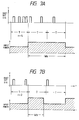
- width of a pulse 101 is short as shown by a waveform of the pulse signal of Fig. 3 because the time interval necessary for the dust particle to pass through the light path is short.
- width of a pulse 102 is large.
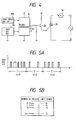
- Fig. 4 is a block diagram of a vacuum cleaner using the above-mentioned dust detection circuit 13.
- the pulse signal produced by the dust detection circuit 13 is inputted into a microprocessor 14 as a control means.
- the microprocessor 14 counts pulses in response to the dust detection signal from the dust detection circuit 13 and detects the number of pulses inputted for a given interval T, for example, in Fig. 5A showing waveform of the dust detection signal, five, two, and four pulses inputted for every given interval T respectively.
- the microprocessor 14 selects input power values for the blower motor 16 from a plurality of preset input power values P1 ⁇ Pn in accordance with count n of pulses inputted for the given interval, as shown in Fig.
- the microprocessor 14 controls a gate of a bi-directional thyristor 15 through a transistor Q1 responsive to port A of the microprocessor 14 in response to the dust detection signal and an output signal of a zero-cross detection circuit 103 to control input power to a blower motor 16 by phase controlling, as shown in Fig. 5C, according to a program stored in the microprocessor 14.
- the zero-cross detection circuit 103 detects when ac line voltage crosses zero volt.
- processing executed by the microprocessor 14 is as follows: When an operator turns on the vacuum cleaner the microprocessor 14 performs initializing, for example clears a memory and resistors and sets an initial time interval value of timer TM1 which causes timer interrupt and it enables zero-cross interrupt, interrupt INT1 in an unshown main routine. Then processing waits interrupts in the main routine.
- the microprocessor 14 starts zero-cross interrupt at step 110 shown in Fig. 6A.
- the microprocessor 14 starts interrupt INT1 processing 130 shown in Fig. 6B and counts up the number of dust particles DC in step 131 and then processing returns to the main routine.
- timer INT starts in step 150, as shown in Fig. 6c and in next step 151, the microprocessor 14 turns on thyristor 15.
- the microprocessor 14 starts zero-cross interrupt in step 110.
- the microprocessor 14 turns off thyristor 15 and set t1 to a timer TM1, built in the microprocessor 14.
- the timer TM1 is started. This causes timer TM1 interrupt when the interval corresponding to the initial value set in the main routine has passed.
- the microprocessor 14 counts up time count TC indicative of the number of zero-crossing of ac line voltage.
- a decision is made as to whether time count TC exceeds a reference value RT1. If the time count TC does not exceed RT1 processing returns to the main routine.
- step 114 a decision is made as to whether the dust count DC exceeds a reference value R1. If the dust count DC exceeds a reference value R1, input power constant P1 is set to a variable P in step 118 and the microprocessor 14 subtracts P from one to obtain off-interval t1 of the thyristor 15. Thus, interval t1 shown in Fig. 5C is changed in accordance with dust count DC. If the dust count DC does not exceed R1 processing proceeds to step 115.
- the thyristor 15 is turned off in step 111 and turned on in step 151 and the interval t1 indicative of off-state is determined (1-P1), (1-P2), and (1-P)in accordance with the number of dust detected for the given interval.
- a second embodiment of a vacuum cleaner Structure of the second embodiment is basically the same as the first embodiment. There is only difference that processing is executed in accordance with a flow chart of Fig. 8.
- Fig. 7A and 7B show control of a second embodiment of the invention.
- the microprocessor 14 counts up pulses of the pulse signal generated by the dust detection circuit 13 for a given interval T.
- the microprocessor 14 changes input power for the blower motor 16 in accordance with the number of the counted pulses and changes time interval of maintaining respective input power values correspondingly.
- Fig. 7A input power of a given value is maintained for an interval Wa corresponding to four pulses inputted for first interval T because four pulses are generated for the first interval T.
- a given input power is maintained for an interval Wb corresponding to two pulses because two pulses are generated for the first interval T.
- Processing is executed in accordance with a flow chart of Fig. 8.
- basic operation is the same as the first embodiment and there are differences in steps 161 - 167.
- the main routine and interrupt routines are basically the same as the first embodiment. Therefore, hereinbelow will be described only different portions.
- step 163, 164, 165, and 167 are added respectively.
- the microprocessor 14 sets time count W1-Wn respectively.
- step 161 is provided between steps 112 and 113 and further a decision is made in step 162. These steps detects when interval for maintaining a determined input power has passed. Thus, the input power determined in steps 117-120 is maintained for interval W1-Wn in accordance with the number of dust particles.
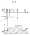
- Fig. 9 shows control of a third embodiment of the invention.
- the microprocessor 14 changes preset values of input power for the blower motor 16 by detecting pulse width and the number of pulses of the pulse signal generated by the dust detection circuit 13, pulse width varying in accordance with size of dust.
- the input power for the blower motor 16 is set in accordance with the number of detected pulses generated for a given interval T.
- the number of dust particles is compensated by pulse width information.
- the number n of detected pulses is multiplied by pulse width compensation factor k.
- the result is used for setting input power of the blower motor 16. For example, when a dust particle of large size is sucked and a pulse with large width is detected, the number of pulses detected is compensated by information of pulse width, so that the number of pulses is set to several counts of pulses equivalently. In this state, sucking force is increased considerably, so that a large power of sucking force is kept for a large size dust particle.
- step 201 a decision is made as to whether dust detection output signal is H. If the dust detection signal is H, processing proceeds to step 202. In step 202, the microprocessor 24 increases a count PWC which indicates pulse width because during H step of the dust detection signal, this count is increased at every zero-cross interrupt. Processing proceeds to step 112 of Fig. 6A. In step 201, if the dust detection signal is L, processing proceeds to step 203. In step 203, the microprocessor 14 compensates the dust count DC with the count PWC of pulse width count. For example, the number n of detected pulses is multiplied by pulse width compensation factor k. In the following step 204, the microprocessor 14 clears count PWC.
- Fig. 11 shows a fourth embodiment of the invention.
- the flow chart of Fig. 11 is used in replacement of the flow chart of Fig. 6B.
- the main routine and other interrupt routine are the same as in the first embodiment.
- interrupt processing starts.
- step 302 a waiting is performed. The interval is several milliseconds.
- the microprocessor 14 detects whether the dust detection signal is H or L. If the dust detection signal is H, the detection signal is true. Thus, in the following step 304, the microprocessor 14 counts up dust count DC. On the other hand, if the dust detection signal is L, the detected signal is not true, i.e., a noise. Thus, counting up of dust count is not performed and processing returns to the main routine directly.
- Fig. 12A shows a waveform of dust detection signal.
- a noise component detected in comparator 11 is removed, as shown in Fig. 12B.
- Figs. 13A and 13B show control of fifth embodiment of the invention.
- the rotating speed is recovered stepwise to the rotating speed set before detection of dust such that the rotating speed is changed at every predetermined interval by a given value to become equal with the initial rotating seed gradually.
- rotating speed of the blower motor 16 is increased to a level 20 from an initial rotating speed 19 and after a predetermined interval, for example one second, has passed, the rotating speed is decreased to a level 21.
- the rotating speed is decreased to a level 22 further and is recovered to the initial level 19 one second after.
- the microprocessor 14 controls rotating speed such that it changes the rotating speed from an initial value to another value; then maintains the another value for a given interval; and further repeatedly changes said rotating speed from the another value by a given value at every given interval until the rotating speed returns to said initial value.
- Fig. 14 shows a flow chart for realizing the above-mentioned embodiment. Processing starts at step 401 when an operator turns on the vacuum cleaner after unshown initializing step is executed. In step 401, the microprocessor 14 sets initial rotating speed IRS to rotating speed RS. Next, in step 402, a decision is made as to whether a dust particle is detected. If a dust particle is detected, processing proceeds to step 403. In step 403, the microprocessor 14 increases rotating speed RS. Next, in step 404, processing waits for interval WI, i.e., one second. If a dust particle is not detected, processing proceeds to step 404 directly. In the following step 405, the microprocessor 14 decreases rotating speed RS.
- WI i.e., one second.
- step 406 a decision is made as to whether rotating speed RS is equal to the initial rotating speed. If rotating speed RS is equal to the initial rotating speed, processing proceeds to step 402. If rotating speed RS is not equal to the initial rotating speed, processing proceeds to step 407. In step 407, the microprocessor 14 detects dust. If there is no dust, waiting of one second is performed in steps 408 and 409. When one second has passed, processing proceeds to step 405 and decreases rotation speed again. This routine is repeated until rotating speed RS equals the initial rotating speed. Rotating speed is controlled by steps 111 of zero-cross interrupt shown is Fig. 6A and interrupt INT1 of Fig. 6B and basic structure is shown in Fig. 4.
- Fig. 15 shows a sixth embodiment of the invention.
- the microprocessor 14 turns off the input power of the blower motor 16 shown in Fig. 4 by controlling the gate of the thyristor 15 when the dust detection circuit 13 does not detect dust for a given interval.
- Processing is executed in accordance with a flow chart of Fig. 15.
- processing starts in step 501 where the microprocessor 14 resets and starts a timer TM2 provided in the microprocessor 14.
- step 502 a decision is made as to whether dust is detected. If dust is detected processing returns to step 501. If dust is not detected, processing proceeds to step 503.
- step 503 a decision is made as to whether the time interval T2 exceeds a predetermined value T1.
- the microprocessor 14 cuts off the input power of the blower motor 16. If the time interval T2 does not exceed the predetermined value T1, processing returns to step 502. As mentioned above, in the vacuum cleaner of the sixth embodiment, the input power of the blower motor 16 is turned off if dust is not detected for a given interval.
- Fig. 16 shows a seventh embodiment of the invention.
- the basic structure of the seventh embodiment is the same as that of the first embodiment.
- plural indication elements (LED) 27 are connected to ports B1-B n of the microprocessor 14 respectively.
- the indication elements 27 are supplied with dc current through current limiting resistors 28.
- the processing of this embodiment, shown in Fig. 17, is basically the same as that of the first embodiment.
- the microprocessor 14 turns on either ports B1-B n in accordance with dust count DC through judging steps 114-116. Therefore, the degree of the dust count is indicated by the indicators 27 to show the degree of uncleanness of the floor, i.e., dust amount.
- Fig. 18 shows an eighth embodiment of the invention.
- the structure of this embodiment is basically the same as that of the seventh embodiment.
- the thyristor 15 is controlled by the microprocessor 14 through a power control circuit 41 and the output port B is connected to a D/A converter.
- the microprocessor 14 outputs dust count DC at the output port B of the microprocessor 14 similar to the seventh embodiment.
- the dust count DC of digital signal is converted into analog signal by the D/A converter 40.
- the output of the D/A converter is compared with triangular wave from a triangular wave generator 43 by a comparator 42.
- the Output of the comparator controls duty of turning on of the thyristor 15.
- the microprocessor 14 executes the process shown in Fig.
- the dust count outputted at the port B of the microprocessor 14 is used for indication of dust.
- the output signal of its ports B1-B n is used for controlling the thyristor 15.
- the above-mentioned structure is provided for separating a driving unit from a control unit.
- the driving unit comprises the D/A converter 40, the power control circuit 41 and the thyristor 15 and the blower motor 16 provided in a housing.
- the control unit comprises the microprocessor 14, the dust detection circuit 13, and the zero-cross detection circuit 17 provided in a handle portion of the vacuum cleaner.
Description
- The invention relates to a vacuum cleaner comprising a blower motor; a dust detection means responsive to dust particles sucked in due to rotation of the blower motor for producing a dust detection signal when detecting the dust particles passing through a portion of a dust sucking passage; and an input power controlling means responsive to an output signal of the dust detection means for controlling the input power of the blower motor.
- Such a vacuum cleaner is known for instance from EP-A-0 217 216, in which the dust detection means comprises photo-transistors which produce an emitter-collector voltage difference signal of a size which is dependent on the incident light intensity. The voltage is subsequently amplified and used to control the blower motor either directly or, in one embodiment, via a monostable flip-flop. The monostable flip-flop is only triggered when sufficient signal is output from the photo-transistors thereby ensuring that control of the blower motor in dependence on the photo-transistor output only takes place when sufficient dust is being sucked in.
- Another prior art vacuum cleaner incorporating many of the same features as EP-A-0 217 216 is disclosed in US 4 680 827. Once again photo-transistors are used to generate a signal related to the amount of dust sucked in, this signal is amplified and then used more or less directly as to control the blower motor. The sucking force is changed in a step like manner between high and low values. Thus, there is the draw-back that the sucking force is not varied in proportion with the amount of dust being sucked into the vacuum cleaner.
- A principal shortcoming of the vacuum cleaners of the prior art referred to is the direct dependence of the blower motor control on the current outputs from the photo-transistors. Limited steps have been taken in the prior art to overcome this shortcoming. For example, capacitors have been employed in an attempt to smooth out rapid fluctuations in the photo-transistor signal voltage. Also diodes have been used connected backwards in order to ensure that signals below a certain threshold are not transmitted and hence do not influence the control of the blower motor. The use of the monostable flip-flop in one embodiment of US 4 680 827 described above also falls into this category.
- It is thus an object of the invention to provide an improved vacuum cleaner in which the blower motor is controlled according to the amount of dust being sucked in in a more ideal manner than in the prior art.
- In a first aspect of the present invention, the object is satisfied in a vacuum cleaner of the initially named kind in that a counting means is connected between the output signal of the dust detection means and the input power controlling means; in that the counting means is provided to count the number of dust particles passing through the portion of the dust sucking passage in a given time interval by using the output signal of the dust detection means; and in that the number of dust particles counted in this given time interval is used to control the input power controlling means.
- In an advantageous development of the first aspect of the present invention, the vacuum cleaner is characterised in that it further comprises a pulse width detecting means connected between the output signal of the dust protection means and the input power controlling means; in that the pulse width detecting means is provided for detecting the width of pulses in the output signal of the dust detection means, these pulses arising from dust particles passing through the portion of the dust sucking passage mentioned; and in that the width of the pulses over a given time interval is used to control the input power controlling means.
- In a second aspect of the present invention, a vacuum cleaner of the initially named kind is characterised in that it further comprises a pulse width detecting means connected between the output signal of the dust detection means and the input power controlling means; in that the pulse width detecting means is provided for detecting the width of pulses in the output signal of the dust detection means, these pulses arising from dust particles passing through the portion of the dust sucking passage mentioned; and in that the width of the pulses over a given time interval is used to control the input power controlling means.
- It is noted that, in contrast to the first aspect of the present invention, in the second aspect of the present invention no counting means is specified.
- The object and features of the present invention will become more readily apparent from the following detailed description taken in conjunction with the accompanying drawings in which:
- Fig. 1 is a cross-sectional view of an optical dust detection portion;
- Fig. 2 is a block diagram of a dust detection circuit of a first embodiment of the invention;
- Fig. 3 shows a waveform of a dust detection signal of the first embodiment;
- Fig. 4 is a block diagram of the first embodiment which is common to first - sixth embodiments;
- Fig. 5A is an explanatory diagram of the first embodiment showing a waveform of the dust detection signal;
- Fig. 5B is a conversion table used in the first embodiment;
- Fig. 5C shows waveforms for controlling input power of Fig. 4;
- Fig. 6A shows a flow chart of the first embodiment;
- Figs. 6B and 6C are partial flow charts of the first embodiment;
- Figs. 7A and 7B show control of a second embodiment;
- Fig. 8 shows a flow chart of the second embodiment;
- Fig. 9 shows waveforms for controlling input power of blower motor of a third embodiment;
- Fig. 10 shows a partial flow chart of the third embodiment;
- Fig. 11 shows a partial flow chart of a fourth embodiment;
- Figs. 12A and 12B show waveform for removing noise component of the third embodiment;
- Fig. 13A and 13B are explanatory diagrams showing rotation speed control of a fifth embodiment;
- Fig. 14 shows a flow chart of the fifth embodiment;
- Fig. 15 shows a flow chart of a sixth embodiment;
- Fig. 16 is a block diagram of a seventh embodiment;
- Fig. 17 shows a flow chart of the seventh and eighth embodiments; and
- Fig. 18 is a block diagram of the eighth embodiment.
- The same or corresponding elements or parts are designated by like references throughout the drawings.
- Referring now to the drawings, Fig. 1 is a cross-sectional view of an optical dust detection portion and Fig. 2 is a block diagram of a dust detection circuit of a first embodiment of the invention. Fig. 4 is a block diagram of the first embodiment which is common to first to sixth embodiments of the invention.
- In Fig. 1, a light emitting device (LED) 3 and a light
sensitive device 4 are provided to a portion ofsuction passage 2 where adust particle 1 passes, thelight emitting device 3 and the lightsensitive device 4 facing each other. The light emitting and the lightsensitive devices transparent holders 5 respectively which are provided for shielding of air and transmitting a light signal from thelight emitting device 3. Fig. 2 is a schematic circuit diagram of adust detection circuit 13. In Fig. 2, a current is supplied to thelight emitting device 3 through aresistor 6 from a dc power supply, so that thelight emitting device 3 emits continuously. The light sensitive device 4 (hereinbelow referred as to phototransistor) receives a light signal from thelight emitting device 3. A collector terminal of thephototransistor 4 is connected to aresistor 7 for supplying a bias current and coupled to a minus input of anamplifier 9 through a capacitor 8 for cutting off a direct current. A plus input of theamplifier 9 is connected to areference potential 10. Therefore, theamplifier 9 produces an output signal varying around potential E₀ of areference voltage 10 wherein only variation of collector potential of the phototransistor 4 (ac component) is amplified. A minus input terminal of acomparator 11 is connected to an output terminal of theamplifier 9. A plus input thereof is connected to areference potential 12. An analog output signal of theamplifier 9 is compared with the reference potential E₁ for waveform shaping. - The operation of the above-mentioned structure, will be described hereinbelow.
- When a
dust particle 1 passes across a light path between the light emittingdevice 3 and thephototransistor 4, thelight particle 1 intercepts the light path between the light emittingdevice 3 and thephototransistor 4, so that the base current of thephototransistor 4 decreases and thus, a collector potential thereof increases. A potential changing component with variation in light intensity is amplified through the capacitor 8 around the reference potential E₀ to detect light intensity change by thedust particle 1 as an analog signal. When the detected analog signal decreases under the reference potential E₁, an output signal of thecomparator 11 changes to H. As mentioned, the analog signal indicative of light intensity change is converted into a digital signal, i.e., a pulse signal or dust detection signal is generated. There is a correlation that:
When a small dust particle passes the light path, width of apulse 101 is short as shown by a waveform of the pulse signal of Fig. 3 because the time interval necessary for the dust particle to pass through the light path is short. On the other hand, in the case of a large dust particle, for example, a paper scrap, width of apulse 102 is large. - Fig. 4 is a block diagram of a vacuum cleaner using the above-mentioned
dust detection circuit 13. In Fig. 4, the pulse signal produced by thedust detection circuit 13 is inputted into amicroprocessor 14 as a control means. Themicroprocessor 14 counts pulses in response to the dust detection signal from thedust detection circuit 13 and detects the number of pulses inputted for a given interval T, for example, in Fig. 5A showing waveform of the dust detection signal, five, two, and four pulses inputted for every given interval T respectively. Themicroprocessor 14 selects input power values for theblower motor 16 from a plurality of preset input power values P₁ ∼ Pn in accordance with count n of pulses inputted for the given interval, as shown in Fig. 5B of a data table stored in ROM of themicroprocessor 14. Themicroprocessor 14 controls a gate of abi-directional thyristor 15 through a transistor Q1 responsive to port A of themicroprocessor 14 in response to the dust detection signal and an output signal of a zero-cross detection circuit 103 to control input power to ablower motor 16 by phase controlling, as shown in Fig. 5C, according to a program stored in themicroprocessor 14. The zero-cross detection circuit 103 detects when ac line voltage crosses zero volt. - As shown in Fig. 6A, processing executed by the
microprocessor 14 is as follows:
When an operator turns on the vacuum cleaner themicroprocessor 14 performs initializing, for example clears a memory and resistors and sets an initial time interval value of timer TM1 which causes timer interrupt and it enables zero-cross interrupt, interrupt INT1 in an unshown main routine. Then processing waits interrupts in the main routine. In response to an output signal of the zero-cross detection circuit 103, themicroprocessor 14 starts zero-cross interrupt atstep 110 shown in Fig. 6A. In response to the dust detection signal, themicroprocessor 14 starts interruptINT1 processing 130 shown in Fig. 6B and counts up the number of dust particles DC instep 131 and then processing returns to the main routine. In response to timer interrupt, timer INT starts instep 150, as shown in Fig. 6c and innext step 151, themicroprocessor 14 turns onthyristor 15. - At every zero-crossing of ac line voltage, the
microprocessor 14 starts zero-cross interrupt instep 110. In thefollowing step 111, themicroprocessor 14 turns offthyristor 15 and set t1 to a timer TM1, built in themicroprocessor 14. Then, the timer TM1 is started. This causes timer TM1 interrupt when the interval corresponding to the initial value set in the main routine has passed. In the succeedingstep 112, themicroprocessor 14 counts up time count TC indicative of the number of zero-crossing of ac line voltage. In the next step, a decision is made as to whether time count TC exceeds a reference value RT1. If the time count TC does not exceed RT1 processing returns to the main routine. If the time count TC1 exceeds RT1 processing proceeds to step 114. This means that the time interval for counting the number of dust particles has passed. Instep 114, a decision is made as to whether the dust count DC exceeds a reference value R1. If the dust count DC exceeds a reference value R1, input power constant P1 is set to a variable P instep 118 and themicroprocessor 14 subtracts P from one to obtain off-interval t₁ of thethyristor 15. Thus, interval t1 shown in Fig. 5C is changed in accordance with dust count DC. If the dust count DC does not exceed R1 processing proceeds to step 115. In succeedingsteps step 114 and correspondingly given input power constant P1, P2, P3, or P4 is set to the variable P where there is a relation that R1>R2>R3 and P1>P2>P3>P4. Thus, the greater the number of dust detected for a given interval indicated by time count TC1 the larger the input power for theblower motor 16. In the succeedingstep 121 ofsteps microprocessor 14 clears dust count DC and time count TC1. Then processing returns to the main routine. Thus, thethyristor 15 is turned off instep 111 and turned on instep 151 and the interval t1 indicative of off-state is determined (1-P1), (1-P2), and (1-P)in accordance with the number of dust detected for the given interval. - Hereinbelow will be described a second embodiment of a vacuum cleaner. Structure of the second embodiment is basically the same as the first embodiment. There is only difference that processing is executed in accordance with a flow chart of Fig. 8. Fig. 7A and 7B show control of a second embodiment of the invention. The
microprocessor 14 counts up pulses of the pulse signal generated by thedust detection circuit 13 for a given interval T. Themicroprocessor 14 changes input power for theblower motor 16 in accordance with the number of the counted pulses and changes time interval of maintaining respective input power values correspondingly. - In an example of Fig. 7A, input power of a given value is maintained for an interval Wa corresponding to four pulses inputted for first interval T because four pulses are generated for the first interval T. In an example of Fig. 7B, a given input power is maintained for an interval Wb corresponding to two pulses because two pulses are generated for the first interval T. There is a relation of maintaining interval W that Wa > Wb, so that the
microprocessor 14 controls maintaining interval W such that the larger the number of pulses generated, the longer the interval is maintained. - Processing is executed in accordance with a flow chart of Fig. 8. However, basic operation is the same as the first embodiment and there are differences in steps 161 - 167. The main routine and interrupt routines are basically the same as the first embodiment. Therefore, hereinbelow will be described only different portions.
- In Fig. 8, after processing of
step steps microprocessor 14 sets time count W1-Wn respectively. On the other hand,step 161 is provided betweensteps step 162. These steps detects when interval for maintaining a determined input power has passed. Thus, the input power determined in steps 117-120 is maintained for interval W1-Wn in accordance with the number of dust particles. - Fig. 9 shows control of a third embodiment of the invention. The
microprocessor 14 changes preset values of input power for theblower motor 16 by detecting pulse width and the number of pulses of the pulse signal generated by thedust detection circuit 13, pulse width varying in accordance with size of dust. - In other words, the input power for the
blower motor 16 is set in accordance with the number of detected pulses generated for a given interval T. The number of dust particles is compensated by pulse width information. For example, the number n of detected pulses is multiplied by pulse width compensation factor k. The result is used for setting input power of theblower motor 16. For example, when a dust particle of large size is sucked and a pulse with large width is detected, the number of pulses detected is compensated by information of pulse width, so that the number of pulses is set to several counts of pulses equivalently. In this state, sucking force is increased considerably, so that a large power of sucking force is kept for a large size dust particle. - Basic processing is carried out according to the flow chart of Fig. 6A and processing shown in Fig. 10 of a flow chart is executed between
steps - Processing starts at
step 201 followingstep 112. Instep 201, a decision is made as to whether dust detection output signal is H. If the dust detection signal is H, processing proceeds to step 202. Instep 202, the microprocessor 24 increases a count PWC which indicates pulse width because during H step of the dust detection signal, this count is increased at every zero-cross interrupt. Processing proceeds to step 112 of Fig. 6A. Instep 201, if the dust detection signal is L, processing proceeds to step 203. Instep 203, themicroprocessor 14 compensates the dust count DC with the count PWC of pulse width count. For example, the number n of detected pulses is multiplied by pulse width compensation factor k. In thefollowing step 204, themicroprocessor 14 clears count PWC. - Fig. 11 shows a fourth embodiment of the invention. The flow chart of Fig. 11 is used in replacement of the flow chart of Fig. 6B. Thus, the main routine and other interrupt routine are the same as in the first embodiment. In Fig. 11, in response to the dust detection signal, interrupt processing starts. In
step 302, a waiting is performed. The interval is several milliseconds. Then, innext step 303 themicroprocessor 14 detects whether the dust detection signal is H or L. If the dust detection signal is H, the detection signal is true. Thus, in the followingstep 304, themicroprocessor 14 counts up dust count DC. On the other hand, if the dust detection signal is L, the detected signal is not true, i.e., a noise. Thus, counting up of dust count is not performed and processing returns to the main routine directly. - Fig. 12A shows a waveform of dust detection signal. In Fig. 12A, a noise component detected in
comparator 11 is removed, as shown in Fig. 12B. - Figs. 13A and 13B show control of fifth embodiment of the invention. In a vacuum cleaner of fifth embodiment of the invention, the rotating speed is recovered stepwise to the rotating speed set before detection of dust such that the rotating speed is changed at every predetermined interval by a given value to become equal with the initial rotating seed gradually. In Fig. 13A, when dust is detected, rotating speed of the
blower motor 16 is increased to alevel 20 from an initialrotating speed 19 and after a predetermined interval, for example one second, has passed, the rotating speed is decreased to alevel 21. Next, after the rotating speed is maintained for one second, the rotating speed is decreased to alevel 22 further and is recovered to theinitial level 19 one second after. In other words, in this embodiment, themicroprocessor 14 controls rotating speed such that it changes the rotating speed from an initial value to another value; then maintains the another value for a given interval; and further repeatedly changes said rotating speed from the another value by a given value at every given interval until the rotating speed returns to said initial value. - Moreover, as shown in Fig. 13B, if dust is detected within interval of maintaining the rotating speed at the
level 22, it is possible to increase the rotating speed tolevel 20 again. - Fig. 14 shows a flow chart for realizing the above-mentioned embodiment. Processing starts at
step 401 when an operator turns on the vacuum cleaner after unshown initializing step is executed. Instep 401, themicroprocessor 14 sets initial rotating speed IRS to rotating speed RS. Next, instep 402, a decision is made as to whether a dust particle is detected. If a dust particle is detected, processing proceeds to step 403. Instep 403, themicroprocessor 14 increases rotating speed RS. Next, instep 404, processing waits for interval WI, i.e., one second. If a dust particle is not detected, processing proceeds to step 404 directly. In thefollowing step 405, themicroprocessor 14 decreases rotating speed RS. Next, instep 406, a decision is made as to whether rotating speed RS is equal to the initial rotating speed. If rotating speed RS is equal to the initial rotating speed, processing proceeds to step 402. If rotating speed RS is not equal to the initial rotating speed, processing proceeds to step 407. Instep 407, themicroprocessor 14 detects dust. If there is no dust, waiting of one second is performed insteps steps 111 of zero-cross interrupt shown is Fig. 6A and interrupt INT1 of Fig. 6B and basic structure is shown in Fig. 4. - Fig. 15 shows a sixth embodiment of the invention. The
microprocessor 14 turns off the input power of theblower motor 16 shown in Fig. 4 by controlling the gate of thethyristor 15 when thedust detection circuit 13 does not detect dust for a given interval. Processing is executed in accordance with a flow chart of Fig. 15. In Fig. 15, processing starts instep 501 where themicroprocessor 14 resets and starts a timer TM2 provided in themicroprocessor 14. In thefollowing step 502, a decision is made as to whether dust is detected. If dust is detected processing returns to step 501. If dust is not detected, processing proceeds to step 503. Instep 503, a decision is made as to whether the time interval T2 exceeds a predetermined value T1. If the time interval T2 exceeds the predetermined value T1, themicroprocessor 14 cuts off the input power of theblower motor 16. If the time interval T2 does not exceed the predetermined value T1, processing returns to step 502. As mentioned above, in the vacuum cleaner of the sixth embodiment, the input power of theblower motor 16 is turned off if dust is not detected for a given interval. - Fig. 16 shows a seventh embodiment of the invention. In Fig. 16, the basic structure of the seventh embodiment is the same as that of the first embodiment. There is a difference that plural indication elements (LED) 27 are connected to ports B₁-Bn of the
microprocessor 14 respectively. Theindication elements 27 are supplied with dc current through current limitingresistors 28. The processing of this embodiment, shown in Fig. 17, is basically the same as that of the first embodiment. There is difference that after steps 117-120, themicroprocessor 14 turns on either ports B₁-Bn in accordance with dust count DC through judging steps 114-116. Therefore, the degree of the dust count is indicated by theindicators 27 to show the degree of uncleanness of the floor, i.e., dust amount. - Fig. 18 shows an eighth embodiment of the invention. The structure of this embodiment is basically the same as that of the seventh embodiment. There is a difference that the
thyristor 15 is controlled by themicroprocessor 14 through apower control circuit 41 and the output port B is connected to a D/A converter. Thus, themicroprocessor 14 outputs dust count DC at the output port B of themicroprocessor 14 similar to the seventh embodiment. The dust count DC of digital signal is converted into analog signal by the D/A converter 40. The output of the D/A converter is compared with triangular wave from atriangular wave generator 43 by acomparator 42. The Output of the comparator controls duty of turning on of thethyristor 15. Themicroprocessor 14 executes the process shown in Fig. 17 in response to zero-cross detection circuit 13 and thedust detection circuit 13. In the seventh embodiment, the dust count outputted at the port B of themicroprocessor 14 is used for indication of dust. On the other hand, in the eighth embodiment, the output signal of its ports B₁-Bn is used for controlling thethyristor 15. The above-mentioned structure is provided for separating a driving unit from a control unit. The driving unit comprises the D/A converter 40, thepower control circuit 41 and thethyristor 15 and theblower motor 16 provided in a housing. The control unit comprises themicroprocessor 14, thedust detection circuit 13, and the zero-cross detection circuit 17 provided in a handle portion of the vacuum cleaner.
Claims (13)
- A vacuum cleaner comprising:
a blower motor (16);
a dust detection means (13) responsive to dust particles (1) sucked in due to rotation of the blower motor (16) for producing a dust detection signal when detecting the dust particles passing through a portion of a dust sucking passage (2);
an input power controlling means (PORT A, Q1, 15; PORT B1-BN, 40, 41, 15) responsive to an output signal of the dust detection means (13) for controlling the input power (P) of the blower motor (16),
characterized in that the vacuum cleaner further comprises
a counting means (103, 14) connected between the output signal of the dust detection means (13) and the input power controlling means (PORT A, Q1, 15; PORT B1-BN, 40, 41, 15),
in that the counting means (103, 14) is provided to count the number of dust particles (DC) passing through said portion of the dust sucking passage (2) in a given time interval (T) using the output signal of the dust detection means (13),
and in that the number of dust particles (DC) counted in the given time interval (T) is used to control the input power controlling means (PORT A, Q1, 15; PORT B1-BN, 40, 41, 15). - A vacuum cleaner as claimed in claim 1,
characterized in that the vacuum cleaner further comprises
a pulse width detecting means (14) connected between the output signal of the dust detection means (13) and the input power controlling means (PORT A,Q1,15; PORT B1-BN,40,41,15),
in that the pulse width detecting means (14) is provided for detecting the widths of pulses in the output signal of the dust detection means (13), said pulses arising from dust particles passing through said portion of the dust sucking passage (2),
and in that the width of the pulses over a given time interval (T) is used to control the input power controlling means (PORT A, Q1, 15; PORT B1-BN, 40, 41, 15). - A vacuum cleaner as claimed in any one of preceding claims,
characterized in that
the input power controlling means (PORT A, Q1, 15; PORT B1-BN, 40, 41, 15) further comprises storing means for storing plural preset input power values (P1 - Pn) and selecting means for selecting an input power value (P) from the plural preset input power values in accordance with the number of dust particles (DC) counted. - A vacuum cleaner as claimed in one of the preceding claims,
characterized in that
the input power controlling means (PORT A, Q1, 15; PORT B1-BN, 40, 41, 15) further comprises means responsive to the dust detection signal for maintaining the input power (P) for an interval (Wa, Wb) determined by the number of dust particles (DC) counted. - A vacuum cleaner as claimed in one of the preceding claims,
characterised in that
the vacuum cleaner further comprises indicating means (27) responsive to the dust detection signal for indicating the degree of detection of dust in accordance with the number of dust particles (DC). - A vacuum cleaner as claimed in one of the preceding claims,
characterized in that
the blower motor (16) and the input power controlling means (PORT A, Q1, 15; PORT B1-BN, 40, 41, 15) are accommodated in a housing, and the dust detection means (13) and the counting means (14) are accommodated in a handle portion of the vacuum cleaner. - A vacuum cleaner comprising:
a blower motor (16);
a dust detection means (13) responsive to dust particles (1) sucked in due to rotation of the blower motor (16) for producing a dust detection signal when detecting the dust particles passing through a portion of a dust sucking passage (2);
an input power controlling means (PORT A, Q1, 15; PORT B1-BN, 40, 41, 15) responsive to an output signal of the dust detection means (13) for controlling the input power (P) of the blower motor (16),
characterized in that the vacuum cleaner further comprises
a pulse width detecting means (14) connected between the output signal of the dust detection means (13) and the input power controlling means (PORT A,Q1,15; PORT B1-BN,40,41,15),
in that the pulse width detecting means (14) is provided for detecting the widths of pulses in the output signal of the dust detection means (13), said pulses arising from single dust particles passing through said portion of the dust sucking passage (2),
and in that the width of the pulses over a given time interval (T) is used to control the input power controlling means (PORT A, Q1, 15; PORT B1-BN, 40, 41, 15). - A vacuum cleaner as claimed in one of the claims 2 to 7,
characterized in that
the dust detection means (13) outputs the dust detection signal only when the pulse width of the dust detection signal exceeds a given value. - A vacuum cleaner as claimed in one of the preceding claims,
characterized in that
the dust detection means (13) ignores the dust detection signal when the pulse width of the dust detection signal is shorter than a given value. - A vacuum cleaner as claimed in one of the preceding claims,
characterized in that
the dust detection means comprises a light emitting device (3) and a light sensitive device (4) both provided such that light from the light emitting device (3) crosses the passage (2) to be received by the light sensitive device (4). - A vacuum cleaner as claimed in one of the preceding claims,
characterized in that
the input power controlling means (PORT A, Q1, 15; PORT B1-BN, 40, 41, 15) controls the input power (P) such that it changes the rotating speed from an initial value (19) to a second value (20); then maintains the second value (20) for a second given interval; and further repeatedly changes the rotating speed from the second value (20) by a given value at every second given interval until the rotating speed returns to the initial value (19). - A vacuum cleaner as claimed in one of the preceding claims,
characterized in that
the input power controlling means (PORT A, Q1, 15; PORT B1-BN, 40, 41, 15) controls the input power (P) such that it cuts off the input power when no pulse of the dust detection signal is inputted thereto for a third given interval. - A vacuum cleaner as claimed in claim 12,
characterized in that
the third given interval is measured with a timer means (TM2) which restarts measurement of time when a dust particle is detected during the measuring to determine the third interval.
Applications Claiming Priority (8)
| Application Number | Priority Date | Filing Date | Title |
|---|---|---|---|
| JP1118260A JPH0728847B2 (en) | 1989-05-11 | 1989-05-11 | Electric vacuum cleaner power control device and display device thereof |
| JP118260/89 | 1989-05-11 | ||
| JP1130409A JPH0618544B2 (en) | 1989-05-23 | 1989-05-23 | Vacuum cleaner controller |
| JP130409/89 | 1989-05-23 | ||
| JP13041289A JPH0618545B2 (en) | 1989-05-23 | 1989-05-23 | Vacuum cleaner |
| JP130412/89 | 1989-05-23 | ||
| JP213376/89 | 1989-08-18 | ||
| JP21337689A JPH0628625B2 (en) | 1989-08-18 | 1989-08-18 | Vacuum cleaner controller |
Publications (2)
| Publication Number | Publication Date |
|---|---|
| EP0397205A1 EP0397205A1 (en) | 1990-11-14 |
| EP0397205B1 true EP0397205B1 (en) | 1994-07-20 |
Family
ID=27470499
Family Applications (1)
| Application Number | Title | Priority Date | Filing Date |
|---|---|---|---|
| EP90108949A Expired - Lifetime EP0397205B1 (en) | 1989-05-11 | 1990-05-11 | Vacuum cleaner |
Country Status (7)
| Country | Link |
|---|---|
| US (1) | US5182833A (en) |
| EP (1) | EP0397205B1 (en) |
| KR (1) | KR930000101B1 (en) |
| AU (1) | AU610777B2 (en) |
| CA (1) | CA2016516C (en) |
| DE (1) | DE69010759T2 (en) |
| ES (1) | ES2060858T3 (en) |
Cited By (2)
| Publication number | Priority date | Publication date | Assignee | Title |
|---|---|---|---|---|
| KR101019789B1 (en) * | 2005-10-25 | 2011-03-04 | 파나소닉 주식회사 | Electric cleaner |
| CN1961802B (en) * | 2005-11-10 | 2013-12-04 | 松下电器产业株式会社 | Electric dust collector |
Families Citing this family (57)
| Publication number | Priority date | Publication date | Assignee | Title |
|---|---|---|---|---|
| ES2072472T3 (en) * | 1990-04-10 | 1995-07-16 | Matsushita Electric Ind Co Ltd | VACUUM CLEANER WITH POWERED CONTROL. |
| JPH0824655B2 (en) * | 1990-11-26 | 1996-03-13 | 松下電器産業株式会社 | Electric vacuum cleaner |
| KR930005714B1 (en) * | 1991-06-25 | 1993-06-24 | 주식회사 금성사 | Attratus and method for controlling speed of suction motor in vacuum cleaner |
| TW212231B (en) * | 1991-08-01 | 1993-09-01 | Hitachi Seisakusyo Kk | |
| KR930003937Y1 (en) * | 1991-08-14 | 1993-06-25 | 주식회사 금성사 | Apparatus for detecting suction dirt for vacuum cleaner |
| JPH0662991A (en) * | 1992-08-21 | 1994-03-08 | Yashima Denki Co Ltd | Vacuum cleaner |
| US5440216A (en) * | 1993-06-08 | 1995-08-08 | Samsung Electronics Co., Ltd. | Robot cleaner |
| DE4327070C1 (en) * | 1993-08-12 | 1995-04-06 | Gerhard Kurz | Device for regulating the power consumption of a vacuum cleaner |
| WO1995027431A1 (en) * | 1994-04-11 | 1995-10-19 | Goyen Controls Co. Pty. Ltd. | Components for and methods of operation of bag house filter/cartridge cleaning systems |
| US5507067A (en) * | 1994-05-12 | 1996-04-16 | Newtronics Pty Ltd. | Electronic vacuum cleaner control system |
| US5925172A (en) * | 1996-06-11 | 1999-07-20 | Amway Corporation | Air treatment system |
| US5815884A (en) * | 1996-11-27 | 1998-10-06 | Yashima Electric Co., Ltd. | Dust indication system for vacuum cleaner |
| US5819367A (en) * | 1997-02-25 | 1998-10-13 | Yashima Electric Co., Ltd. | Vacuum cleaner with optical sensor |
| US8412377B2 (en) | 2000-01-24 | 2013-04-02 | Irobot Corporation | Obstacle following sensor scheme for a mobile robot |
| US8788092B2 (en) | 2000-01-24 | 2014-07-22 | Irobot Corporation | Obstacle following sensor scheme for a mobile robot |
| US6956348B2 (en) * | 2004-01-28 | 2005-10-18 | Irobot Corporation | Debris sensor for cleaning apparatus |
| US6690134B1 (en) * | 2001-01-24 | 2004-02-10 | Irobot Corporation | Method and system for robot localization and confinement |
| US7571511B2 (en) * | 2002-01-03 | 2009-08-11 | Irobot Corporation | Autonomous floor-cleaning robot |
| US8396592B2 (en) * | 2001-06-12 | 2013-03-12 | Irobot Corporation | Method and system for multi-mode coverage for an autonomous robot |
| US7429843B2 (en) * | 2001-06-12 | 2008-09-30 | Irobot Corporation | Method and system for multi-mode coverage for an autonomous robot |
| US9128486B2 (en) | 2002-01-24 | 2015-09-08 | Irobot Corporation | Navigational control system for a robotic device |
| US8428778B2 (en) | 2002-09-13 | 2013-04-23 | Irobot Corporation | Navigational control system for a robotic device |
| US8386081B2 (en) * | 2002-09-13 | 2013-02-26 | Irobot Corporation | Navigational control system for a robotic device |
| US7332890B2 (en) | 2004-01-21 | 2008-02-19 | Irobot Corporation | Autonomous robot auto-docking and energy management systems and methods |
| WO2005098476A1 (en) | 2004-03-29 | 2005-10-20 | Evolution Robotics, Inc. | Method and apparatus for position estimation using reflected light sources |
| ATE536577T1 (en) | 2004-06-24 | 2011-12-15 | Irobot Corp | REMOTE CONTROLLED SEQUENCE CONTROL AND METHOD FOR AN AUTONOMOUS ROBOTIC DEVICE |
| US7706917B1 (en) | 2004-07-07 | 2010-04-27 | Irobot Corporation | Celestial navigation system for an autonomous robot |
| US8972052B2 (en) | 2004-07-07 | 2015-03-03 | Irobot Corporation | Celestial navigation system for an autonomous vehicle |
| US8392021B2 (en) * | 2005-02-18 | 2013-03-05 | Irobot Corporation | Autonomous surface cleaning robot for wet cleaning |
| US7620476B2 (en) * | 2005-02-18 | 2009-11-17 | Irobot Corporation | Autonomous surface cleaning robot for dry cleaning |
| ES2346343T3 (en) | 2005-02-18 | 2010-10-14 | Irobot Corporation | AUTONOMOUS SURFACE CLEANING ROBOT FOR DRY AND WET CLEANING. |
| US8930023B2 (en) * | 2009-11-06 | 2015-01-06 | Irobot Corporation | Localization by learning of wave-signal distributions |
| ES2706727T3 (en) | 2005-12-02 | 2019-04-01 | Irobot Corp | Robot system |
| EP1969438B1 (en) | 2005-12-02 | 2009-09-09 | iRobot Corporation | Modular robot |
| KR101214715B1 (en) | 2005-12-02 | 2012-12-21 | 아이로보트 코퍼레이션 | coverage robot mobility |
| EP2466411B1 (en) * | 2005-12-02 | 2018-10-17 | iRobot Corporation | Robot system |
| EP2816434A3 (en) | 2005-12-02 | 2015-01-28 | iRobot Corporation | Autonomous coverage robot |
| JP2007185414A (en) * | 2006-01-16 | 2007-07-26 | Matsushita Electric Ind Co Ltd | Vacuum cleaner |
| US7509707B2 (en) * | 2006-02-06 | 2009-03-31 | Panasonic Corporation Of North America | Floor cleaning apparatus with dirt detection sensor |
| EP2548492B1 (en) | 2006-05-19 | 2016-04-20 | iRobot Corporation | Removing debris from cleaning robots |
| US8417383B2 (en) | 2006-05-31 | 2013-04-09 | Irobot Corporation | Detecting robot stasis |
| KR101301834B1 (en) | 2007-05-09 | 2013-08-29 | 아이로보트 코퍼레이션 | Compact autonomous coverage robot |
| US8461964B2 (en) * | 2007-10-12 | 2013-06-11 | Commscope, Inc. Of North Carolina | Communications patching systems with radio frequency identification antenna switching circuits |
| JP5073609B2 (en) * | 2008-08-11 | 2012-11-14 | 日東電工株式会社 | Manufacturing method of optical waveguide |
| US20100236013A1 (en) * | 2009-03-17 | 2010-09-23 | Electrolux Home Care Products, Inc. | Vacuum Cleaner Sensor |
| TWI403300B (en) * | 2009-11-16 | 2013-08-01 | Ind Tech Res Inst | Method for controlling cleaning apparatus |
| EP3192419B1 (en) | 2010-02-16 | 2021-04-07 | iRobot Corporation | Vacuum brush |
| SE534962C2 (en) | 2010-06-29 | 2012-02-28 | Electrolux Ab | Dust detection system for a vacuum cleaner |
| SE534963C2 (en) | 2010-06-29 | 2012-02-28 | Electrolux Ab | Dust indicator for a vacuum cleaner |
| KR101483541B1 (en) * | 2010-07-15 | 2015-01-19 | 삼성전자주식회사 | Autonomous cleaning device, maintenance station and cleaning system having them |
| WO2014072469A1 (en) | 2012-11-09 | 2014-05-15 | Aktiebolaget Electrolux | Cyclone dust separator arrangement, cyclone dust separator and cyclone vacuum cleaner |
| CN103840809A (en) * | 2012-11-20 | 2014-06-04 | 苏州工业园区新宏博通讯科技有限公司 | Bidirectional-silicon-controlled-rectifier trigger circuit |
| CN105549674A (en) * | 2016-01-07 | 2016-05-04 | 江苏源能环境工程有限公司 | High-power solid state high-voltage pulse power source |
| US10704250B2 (en) | 2016-10-28 | 2020-07-07 | Milwaukee Electric Tool Corporation | Sewer cleaning machine |
| CN108283460B (en) * | 2017-01-09 | 2021-04-09 | 松下家电研究开发(杭州)有限公司 | Dust suction device |
| US11505229B2 (en) | 2018-04-13 | 2022-11-22 | Milwaukee Electric Tool Corporation | Tool support |
| KR20210029583A (en) * | 2019-09-06 | 2021-03-16 | 삼성전자주식회사 | Cleaner and control method thereof |
Family Cites Families (5)
| Publication number | Priority date | Publication date | Assignee | Title |
|---|---|---|---|---|
| NL7212108A (en) * | 1972-09-06 | 1974-03-08 | ||
| DE3431164A1 (en) * | 1984-02-08 | 1985-08-14 | Gerhard 7262 Althengstett Kurz | VACUUM CLEANER |
| DE3534621A1 (en) * | 1985-09-28 | 1987-04-02 | Interlava Ag | VACUUM CLEANER |
| JPS63246125A (en) * | 1987-04-02 | 1988-10-13 | 松下電器産業株式会社 | Electric cleaner |
| KR910009450B1 (en) * | 1987-10-16 | 1991-11-16 | 문수정 | Superconducting coils and method of manufacturing the same |
-
1990
- 1990-05-03 US US07/518,402 patent/US5182833A/en not_active Expired - Lifetime
- 1990-05-09 AU AU54879/90A patent/AU610777B2/en not_active Expired
- 1990-05-10 CA CA002016516A patent/CA2016516C/en not_active Expired - Lifetime
- 1990-05-11 DE DE69010759T patent/DE69010759T2/en not_active Expired - Lifetime
- 1990-05-11 EP EP90108949A patent/EP0397205B1/en not_active Expired - Lifetime
- 1990-05-11 ES ES90108949T patent/ES2060858T3/en not_active Expired - Lifetime
- 1990-05-11 KR KR1019900006698A patent/KR930000101B1/en not_active IP Right Cessation
Cited By (2)
| Publication number | Priority date | Publication date | Assignee | Title |
|---|---|---|---|---|
| KR101019789B1 (en) * | 2005-10-25 | 2011-03-04 | 파나소닉 주식회사 | Electric cleaner |
| CN1961802B (en) * | 2005-11-10 | 2013-12-04 | 松下电器产业株式会社 | Electric dust collector |
Also Published As
| Publication number | Publication date |
|---|---|
| AU5487990A (en) | 1990-11-29 |
| KR930000101B1 (en) | 1993-01-09 |
| EP0397205A1 (en) | 1990-11-14 |
| DE69010759D1 (en) | 1994-08-25 |
| CA2016516A1 (en) | 1990-11-12 |
| US5182833A (en) | 1993-02-02 |
| KR900017542A (en) | 1990-12-19 |
| ES2060858T3 (en) | 1994-12-01 |
| AU610777B2 (en) | 1991-05-23 |
| DE69010759T2 (en) | 1994-10-27 |
| CA2016516C (en) | 1999-08-17 |
Similar Documents
| Publication | Publication Date | Title |
|---|---|---|
| EP0397205B1 (en) | Vacuum cleaner | |
| US5144715A (en) | Vacuum cleaner and method of determining type of floor surface being cleaned thereby | |
| EP0584743B1 (en) | Vacuum cleaner | |
| EP0371632B1 (en) | Vacuum cleaner with device for adjusting sensitivity of dust sensor | |
| CA2040079C (en) | Vacuum cleaner with fuzzy control and a method of vacuum cleaning | |
| US4680827A (en) | Vacuum cleaner | |
| EP0308517B1 (en) | Vaccum cleaner | |
| US6055702A (en) | Vacuum cleaner | |
| EP0488884A1 (en) | Vacuum cleaner | |
| US6255792B1 (en) | Intelligent suction device capable of automatically adapting the suction force according to the conditions of the surface, particularly for vacuum cleaners and the like | |
| JPH10507958A (en) | Vacuum cleaner with output control depending on operating mode of electric brush | |
| GB2079010A (en) | Optical detection device | |
| US20090309639A1 (en) | processing method and apparatus for energy saving of an active infrared induction instrument powered by a dry battery | |
| JPH02297329A (en) | Vacuum cleaner power control device and its display device | |
| JP2001008871A (en) | Vacuum cleaner | |
| JP2969729B2 (en) | Electric vacuum cleaner | |
| JPH0339126A (en) | Control circuit of vacuum cleaner | |
| JPH02307420A (en) | Electric power-controller for electric vacuum cleaner | |
| JP3063150B2 (en) | Electric vacuum cleaner | |
| JPH05154076A (en) | Vacuum cleaner | |
| JP2956204B2 (en) | Electric vacuum cleaner | |
| KR200147243Y1 (en) | Device for detecting the dust of a vacuum cleaner | |
| JPH05199972A (en) | Vacuum cleaner | |
| JP2882010B2 (en) | Electric vacuum cleaner | |
| JPH04122340A (en) | Vacuum cleaner |
Legal Events
| Date | Code | Title | Description |
|---|---|---|---|
| PUAI | Public reference made under article 153(3) epc to a published international application that has entered the european phase |
Free format text: ORIGINAL CODE: 0009012 |
|
| 17P | Request for examination filed |
Effective date: 19900511 |
|
| AK | Designated contracting states |
Kind code of ref document: A1 Designated state(s): DE ES GB |
|
| 17Q | First examination report despatched |
Effective date: 19920518 |
|
| GRAA | (expected) grant |
Free format text: ORIGINAL CODE: 0009210 |
|
| AK | Designated contracting states |
Kind code of ref document: B1 Designated state(s): DE ES GB |
|
| REF | Corresponds to: |
Ref document number: 69010759 Country of ref document: DE Date of ref document: 19940825 |
|
| REG | Reference to a national code |
Ref country code: ES Ref legal event code: FG2A Ref document number: 2060858 Country of ref document: ES Kind code of ref document: T3 |
|
| PLBE | No opposition filed within time limit |
Free format text: ORIGINAL CODE: 0009261 |
|
| STAA | Information on the status of an ep patent application or granted ep patent |
Free format text: STATUS: NO OPPOSITION FILED WITHIN TIME LIMIT |
|
| 26N | No opposition filed | ||
| REG | Reference to a national code |
Ref country code: GB Ref legal event code: IF02 |
|
| PGFP | Annual fee paid to national office [announced via postgrant information from national office to epo] |
Ref country code: ES Payment date: 20090609 Year of fee payment: 20 |
|
| PGFP | Annual fee paid to national office [announced via postgrant information from national office to epo] |
Ref country code: DE Payment date: 20090511 Year of fee payment: 20 |
|
| PGFP | Annual fee paid to national office [announced via postgrant information from national office to epo] |
Ref country code: GB Payment date: 20090506 Year of fee payment: 20 |
|
| REG | Reference to a national code |
Ref country code: GB Ref legal event code: PE20 Expiry date: 20100510 |
|
| REG | Reference to a national code |
Ref country code: ES Ref legal event code: FD2A Effective date: 20100512 |
|
| PG25 | Lapsed in a contracting state [announced via postgrant information from national office to epo] |
Ref country code: ES Free format text: LAPSE BECAUSE OF EXPIRATION OF PROTECTION Effective date: 20100512 |
|
| PG25 | Lapsed in a contracting state [announced via postgrant information from national office to epo] |
Ref country code: GB Free format text: LAPSE BECAUSE OF EXPIRATION OF PROTECTION Effective date: 20100510 |
|
| PG25 | Lapsed in a contracting state [announced via postgrant information from national office to epo] |
Ref country code: DE Free format text: LAPSE BECAUSE OF EXPIRATION OF PROTECTION Effective date: 20100511 |