EP0396204A2 - Verfahren und Vorrichtung zum Verbinden von Futterrohren - Google Patents
Verfahren und Vorrichtung zum Verbinden von Futterrohren Download PDFInfo
- Publication number
- EP0396204A2 EP0396204A2 EP90201122A EP90201122A EP0396204A2 EP 0396204 A2 EP0396204 A2 EP 0396204A2 EP 90201122 A EP90201122 A EP 90201122A EP 90201122 A EP90201122 A EP 90201122A EP 0396204 A2 EP0396204 A2 EP 0396204A2
- Authority
- EP
- European Patent Office
- Prior art keywords
- tubular
- welding ring
- mandrel
- ring
- tubular elements
- Prior art date
- Legal status (The legal status is an assumption and is not a legal conclusion. Google has not performed a legal analysis and makes no representation as to the accuracy of the status listed.)
- Granted
Links
Images
Classifications
-
- F—MECHANICAL ENGINEERING; LIGHTING; HEATING; WEAPONS; BLASTING
- F16—ENGINEERING ELEMENTS AND UNITS; GENERAL MEASURES FOR PRODUCING AND MAINTAINING EFFECTIVE FUNCTIONING OF MACHINES OR INSTALLATIONS; THERMAL INSULATION IN GENERAL
- F16L—PIPES; JOINTS OR FITTINGS FOR PIPES; SUPPORTS FOR PIPES, CABLES OR PROTECTIVE TUBING; MEANS FOR THERMAL INSULATION IN GENERAL
- F16L13/00—Non-disconnectable pipe joints, e.g. soldered, adhesive, or caulked joints
- F16L13/02—Welded joints
- F16L13/0218—Welded joints having an inner or outer ring
- F16L13/0236—Welded joints having an inner or outer ring having an outer ring
-
- B—PERFORMING OPERATIONS; TRANSPORTING
- B23—MACHINE TOOLS; METAL-WORKING NOT OTHERWISE PROVIDED FOR
- B23K—SOLDERING OR UNSOLDERING; WELDING; CLADDING OR PLATING BY SOLDERING OR WELDING; CUTTING BY APPLYING HEAT LOCALLY, e.g. FLAME CUTTING; WORKING BY LASER BEAM
- B23K20/00—Non-electric welding by applying impact or other pressure, with or without the application of heat, e.g. cladding or plating
- B23K20/12—Non-electric welding by applying impact or other pressure, with or without the application of heat, e.g. cladding or plating the heat being generated by friction; Friction welding
- B23K20/129—Non-electric welding by applying impact or other pressure, with or without the application of heat, e.g. cladding or plating the heat being generated by friction; Friction welding specially adapted for particular articles or work
-
- E—FIXED CONSTRUCTIONS
- E21—EARTH OR ROCK DRILLING; MINING
- E21B—EARTH OR ROCK DRILLING; OBTAINING OIL, GAS, WATER, SOLUBLE OR MELTABLE MATERIALS OR A SLURRY OF MINERALS FROM WELLS
- E21B17/00—Drilling rods or pipes; Flexible drill strings; Kellies; Drill collars; Sucker rods; Cables; Casings; Tubings
- E21B17/02—Couplings; joints
- E21B17/08—Casing joints
-
- E—FIXED CONSTRUCTIONS
- E21—EARTH OR ROCK DRILLING; MINING
- E21B—EARTH OR ROCK DRILLING; OBTAINING OIL, GAS, WATER, SOLUBLE OR MELTABLE MATERIALS OR A SLURRY OF MINERALS FROM WELLS
- E21B19/00—Handling rods, casings, tubes or the like outside the borehole, e.g. in the derrick; Apparatus for feeding the rods or cables
- E21B19/16—Connecting or disconnecting pipe couplings or joints
Definitions
- the invention relates to a method and device for joining well tubulars.
- elongate strings of well tubulars have to be inserted into the well to protect the well against caving in and to facilitate a safe production of oil and gas through the well.
- the conventional way of protecting a well against caving in is to create a casing by screwing together one or more strings of casing pipes that are lowered into the well and cemented in place.
- Production of oil and gas takes place via one or more elongate production strings, consisting of production tubes that are interconnected by screw thread couplings, which production strings are suspended within the interior of the casing.
- the present invention aims to provide a method and device for joining well tubulars by friction welding in an efficient and safe manner.
- the device should be easily movable such that it can be mounted on a drilling or workover rig.
- the method should be performed by drilling operators without broad expertise on welding technology, while use can be made of existing hoisting and rig equipment.
- the method according to the invention comprises the steps of: - lowering a first tubular element into a well until the upper end of the element is located in a substantially vertical orientation near the entrance of the well, - positioning a welding ring on top of said tubular element, - hoisting a second tubular element to a substantially vertical position above the welding ring, - fixing the tubular elements in axial alignment with each other by means of clamps of a friction welding device, - rotating the weiding ring by means of the friction welding device relative to the tubular elements while deforming the welding ring in radial sense such that the welding ring is in contact with the tubular elements thereby generating sufficient frictional heat to create a friction weld between the ring and the tubular elements, and - lowering the interconnected tubular elements into the well.
- the device comprises: - means for maintaining a first tubular element in a substantially vertical position suspended in a well while the upper end of the element is located near the entrance of the well, - means for hoisting a second tubular element to a substantially vertical position above the suspended tubular element and a welding ring positioned on top of this element, - clamps for fixing the tubular elements in axial alignment with each other, and - a rotatable sleeve mounted between said clamps for rotating the welding ring relative to said tubular elements while deforming the welding ring in radial sense such that the welding ring is in contact with the tubular elements, thereby generating sufficient frictional heat to create a friction weld between the welding ring and the tubular elements.
- the substantially vertical orientation of the tubular elements during the friction welding process has the advantage that the upper end of the first tubular element, which is suspended in the well, can be firmly fixed near the drilling floor whereupon the second tubular element can be hoisted on top of the first element by means of the crown block of the drilling rig so that the welding process can be carried out with a relatively small mobile welding device which does not require a heavy foundation frame.
- the interior and exterior of the tubular elements in the region of the welding ring are sealed during the step of the rotating the ring so as to avoid any contact between the hot ring and flammable gases that may escape form the well. Sealing of the space around the welding ring may be achieved by creating around the ring a partly open and for example bell-shaped chamber into which an inert gas is injected.
- a sealed chamber around the welding ring by rotating the welding ring around the tubular elements by means of a tubular mid section which carries claw means for gripping the welding ring, whilst the mid section is rotatably and sealingly connected by a bearing unit and sealing rings to a pair of tubular end sections of the welding device, which end sections are each clamped around the tubular elements by one of the clamps.
- the mandrel is further equipped with a pair of clamps that are positioned opposite to the clamps on the end sections so that during the welding process the tubular elements are clamped between the pairs of internal and external clamps which allows a high contact pressure to be exerted by the clamps to the tubular elements without the risk of deformation or rupture of these elements.
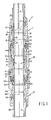
- Figure 1 shows a friction welding device consisting of a mandrel 1 and an external portion 2 arranged around a first and a second tubular element 3 and 4, respectively, which elements are to be interconnected by the welding ring 5 to a string of well tubulars.
- the external portion of the device is shown in an inactive position whereas at the left side of these Figures it is shown in an active position in which it is clamped to the tubular elements 3 and 4 and the welding ring 5.
- the external portion 2 of the device consists of an upper tubular end section 7 and a lower tubular end section 8 and a tubular mid section 10 which is rotatably connected to the end sections 7 and 8 by two bearing units 11.
- a number of sealing rings 12 are arranged between adjacent surfaces of the mid section 10 and the end sections 7 and 8, which together with a flexible sealing ring 13 and 13A of each end section 7 and 8 create a confined space 14 between the inner surface of the outer portion 2 of the friction welding device and the outer surfaces of the tubular elements 3 and 4 in the region of the welding ring 5.
- the tubular mid section 10 consists of a pair of sleeves 15 that are screwed together, an annular piston 16 having a tapered inner surface and a series of claw segments 17 having tapered outer surfaces that are pressed against the tapered inner surface of the piston 16 by an expansion ring 18.
- the annular piston 16 is at one of its ends slidably arranged inside an annular cylinder 19 which is in fluid communication with a fluid feed 20 via radial bores and an annular groove 21.
- the claw segments 17 are clamped around the welding ring 5 by pumping hydraulic fluid via the fluid feed 20 into the cylinder 19 thereby urging the piston 16 to move in upward direction against the action of a spring 22 from the position shown at the right side of Fig. 1 to the position at the left side of Fig. 1.
- the claw segments 17 are pressed onto the welding ring 5 whilst rotation of the segments 17 relative to the rotating mid section 10 is prevented by radial grooves 24 in abutting radial end surfaces of the upper sleeve 15 and the segments 17.
- the upper and lower tubular end sections 7 and 8 of the external portion 2 of the welding device are identical to each other. Therefore only the construction and operation of the upper tubular end section 7 will be described in detail.
- the upper tubular end section 7 consists of two sleeves 30 and 31 which are screwed together, a cap nut 32, a guide ring 33, a series of wedges 34, an actuator ring 35 and the flexible sealing ring 13.
- the upper tubular end section 7 is clamped around the second tubular element 4 by screwing the cap nut 32 into the sleeve 30 from the position shown at the right side of Fig. 1 to the position shown at the left side of Fig. 1.
- the downward motion of the cap screw 32 is transferred via the guide ring 33 to the wedges 34 which slide along a tapered inner surface 38 of the sleeve 30 and are pressed onto the outer surface of the second tubular element 4.
- the lower tips 39 of the wedges 34 thereby press the actuator ring 35 in downward direction which causes the flexible sealing ring 13 to be pressed against the outer surface of the second tubular element 4 thereby providing a fluid tight seal between the second tubular element 4 and the upper tubular end section 7 of the welding device.
- the lower tubular end section 8 consists of sleeves 30A and 31A which are screwed together, a cap nut 32A, a guide ring 33A, a series of wedges 34A, an actuator ring 35A and the flexible sealing ring 13A.
- Operation of the lower tubular end section 8 is similar to operation of the upper tubular end section 7 described above.
- cap nuts 32 and 32A for activating the wedges 34 and 34A may be replaced by hydraulic pistons or other actuator mechanisms.
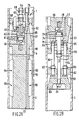
- the mandrel 1 comprises a central body 50 which carries at its lower end a sealing cup 51 and around which an upper and a lower wedge assembly 52 and 53 and a split weld supporting sleeve 54 are arranged.
- the split weld supporting sleeve 54 consists of two sleeve segments that are interconnected by dowels 55. Each sleeve segment may be equipped with electrical heater coils that are fed via electrical conduits passing through the central body 50.
- the upper wedge assembly 52 consists of a series of wedges that are clamped between a tapered outer surface 57 of the central body 50 and inner surface of the second tubular element 4 by a downward motion of an upper actuator disc 58 relative to the central body 50.
- the upper actuator disc 58 is connected to a hollow actuator rod 59 by a locking nut 60.
- the actuator rod 59 carries near its lower end a piston and stuffing box assembly 61 which is slidably secured inside a cylindrical chamber 62 formed in the central body 50.
- the chamber 62 is closed at its top by a cap 63 and by pumping fluid into the chamber 62 via a fluid feed conduit 64 and a bore 65 in the actuator rod 59, the actuator rod 59 is pushed into the upper end of the central body 50 against the action of a spring 66, thereby inducing the upper actuator disc 58 to clamp the upper wedge assembly 52 against the inner surface of the second tubular element 4.
- the lower wedge assembly 53 is clamped against the inner surface of the first tubular element 3 by an upward motion of a lower actuator disc 70 relative to the central body 50.
- the lower actuator disc 70 is connected to an elongated rod 71 by a locking nut 72.
- the rod 71 carries near its upper end a piston and stuffing box assembly 73 which is slidably arranged inside a cylindrical chamber 74 formed at the lower end of the central body 50.
- the chamber 74 is closed at its lower end by a cap 75 and by pumping fluid into the chamber 74 via fluid feed conduit 76 and a bore 77 passing through the central body 50 the rod 71 is pushed into the lower end of the body 5u against the action of a spring 78, thereby inducing the lower actuator disc 70 to clamp the assembly of wedges 51 against the inner wall of the first tubular element 3.
- the rod 71 is at its lower end connected to a trapezoidal body 80 by a nut 81.
- the sealing cap 51 is held at a location 3ust above the body by means of a support plate 82 which is locked by nuts 83 to a series of spacer rods 84.
- the spacer rods 84 pass through openings in the lower actuator disc 70 and are screwed into recesses 85 at the lower end of the central body 50.
- connection of the trapezoidal body 80 and the lower actuator disc 70 to the rod 71 facilitates a simultaneous activation of the sealing cup 51 and the lower wedge assembly 53. If the rod 71 is pulled into the lower end of the central body 50 by injecting fluid via the bore 77 into the chamber the wedge assembly 53 is clamped against the inner wall of the first tubular element 3 by the actuator disc 70 whereas at the same time the sealing cup 51 is clamped to the inner wall of the tubular element 3 by the movement of the trapezoidal body 80 towards the support plate 82.
- a preferred procedure for joining well tubulars with the device shown in Figures 1, 2A and 2b is as follows.
- the external portion 2 of the friction device is mounted or suspended in a substantially vertical position above the wellhead (not shown) of the well in which the well tubulars are to be inserted, for example to create a casing string or one or more production strings.
- the tubular elements for use in the string or strings are stored in a slant or vertical orientation in a pipe rack near the wellhead, and the external portion of the friction welding device is located above the well (not shown).
- a first tubular element 3 is then retrieved from the pipe rack and lowered through the external portion 2 of the friction welding device into the well until the upper end of this element is located in a vertical orientation just above the upper clamp nut 32 of the external portion 2 of the friction welding device, whereupon the welding ring 5 is laid on top of the first tubular element 3.
- the internal mandrel 1 of the device whilst it is suspended on a hoisting cable 6 carried by for example the crown block of a drilling rig mounted above the well, is lowered through the second tubular element 4 until the mandrel 1 protrudes about halfway from the lower end of this element 4.
- the mandrel 1 is clamped to the inner wall of the second tubular element 4 by activating the upper wedge assembly 52 by injecting fluid into the chamber 62 via the conduit 64, whereupon the mandrel 1, with the second tubular element 4 attached thereto, is hoisted by the cable 6 to a vertical position above the first tubular element 3.
- the lower part of the mandrel 1 is stabbed through the welding ring 5 into the upper end of the first tubular element 3 until the lower end of the second tubular element 4 rests upon the welding ring 5 and/or the upper end of the first tubular element 3.
- the external portion 2 of the device is axially moved relative to the mandrel 1 either by lowering the mandrel 1 with the tubular elements 3 and 4 clamped thereto, or by raising the external portion 2 of the device to a higher level above the wellhead, until the welding ring 5 is surrounded by the claw segments 17.
- the wedges 34A and the flexible sealing ring 13A of the lower tubular end section 8 of the external portion 2 of the device are clamped around the first tubular element 3 by tightening of the cap nut 32A, whereas the wedges 34 and the flexible sealing ring 13 of the upper tubular end section 7 of the external portion of the device are clamped around the second tubular element 4 by tightening the cap nut 32.
- the axial spacing between the wedges 34 and 34A is identical to the axial spacing between the wedge assemblies 52 and 53 of the mandrel 1 a high radial clamping force may be exerted between the wedges and the walls of the tubular elements 3 and 4 without the risk of deformation or rupture of these elements.
- the claw segments 17 exert a predetermined radial force to the welding ring 5.
- the magnitude of the radial force may be adjusted in relation to either the radial compression force exerted to the ring or to the radial deformation of the ring.
- the radial force exerted to the welding ring 5 and the speed of rotation of the conical inner surface of the welding ring 5 over the conical outer surfaces of the ends of the tubular elements 3 and 4 are of such a magnitude that sufficient frictional heat is generated to create a frictional weld between the welding ring 5 and tubular elements 3 and 4.
- a heat treatment of the weld and interconnected ends of the tubular elements 3 and 4 is carried out by heating the welding ring 5 and said ends of the tubular elements by means of the heating coils in the split weld supporting sleeve 54 of the mandrel 1.
- the heat treatment may also be conducted by an external heating device (not shown).
- the mandrel 1 and external portion 2 of the device are released from the welding ring 5 and the tubular elements 3 and 4 by releasing the claw segments 16 and the assemblies of wedges 34, 34A, 52 and 53 whereupon the created weld may be inspected.
- a next tubular element may be connected on top of the second tubular element 4 by repeating the friction welding process described above, which process may be repeated again and again until the string of well tubulars has its required length.
- the first tubular element was lowered into the well through the external portion of the friction welding device.
- the first tubular element can be lowered into the borehole and the external portion of the friction welding device can be arranged on top of the first tubular element.
Landscapes
- Engineering & Computer Science (AREA)
- Geology (AREA)
- Mechanical Engineering (AREA)
- Life Sciences & Earth Sciences (AREA)
- Mining & Mineral Resources (AREA)
- General Life Sciences & Earth Sciences (AREA)
- Fluid Mechanics (AREA)
- Environmental & Geological Engineering (AREA)
- Physics & Mathematics (AREA)
- Geochemistry & Mineralogy (AREA)
- General Engineering & Computer Science (AREA)
- Pressure Welding/Diffusion-Bonding (AREA)
- Earth Drilling (AREA)
- Non-Disconnectible Joints And Screw-Threaded Joints (AREA)
- Lining Or Joining Of Plastics Or The Like (AREA)
Applications Claiming Priority (2)
| Application Number | Priority Date | Filing Date | Title |
|---|---|---|---|
| GB898910118A GB8910118D0 (en) | 1989-05-03 | 1989-05-03 | Method and device for joining well tubulars |
| GB8910118 | 1989-05-03 |
Publications (3)
| Publication Number | Publication Date |
|---|---|
| EP0396204A2 true EP0396204A2 (de) | 1990-11-07 |
| EP0396204A3 EP0396204A3 (de) | 1991-04-24 |
| EP0396204B1 EP0396204B1 (de) | 1993-08-25 |
Family
ID=10656127
Family Applications (1)
| Application Number | Title | Priority Date | Filing Date |
|---|---|---|---|
| EP90201122A Expired - Lifetime EP0396204B1 (de) | 1989-05-03 | 1990-05-03 | Verfahren und Vorrichtung zum Verbinden von Futterrohren |
Country Status (9)
| Country | Link |
|---|---|
| US (1) | US5071053A (de) |
| EP (1) | EP0396204B1 (de) |
| JP (1) | JP2747084B2 (de) |
| AU (1) | AU620711B2 (de) |
| CA (1) | CA2015844C (de) |
| DE (1) | DE69002860T2 (de) |
| GB (1) | GB8910118D0 (de) |
| MY (1) | MY105702A (de) |
| NO (1) | NO301032B1 (de) |
Cited By (9)
| Publication number | Priority date | Publication date | Assignee | Title |
|---|---|---|---|---|
| WO1998021002A1 (de) * | 1996-11-11 | 1998-05-22 | Untergrundspeicher- Und Geotechnologie-Systeme Gmbh | Verfahren und vorrichtung zum verbinden von bauteilen |
| US6078031A (en) * | 1997-02-04 | 2000-06-20 | Shell Research Limited | Method and device for joining oilfield tubulars |
| NL1011069C2 (nl) * | 1999-01-19 | 2000-07-20 | Well Engineering Partners B V | Werkwijze en installatie voor het inbrengen van een buis in een boorgat in de aardbodem. |
| US6634540B1 (en) * | 1999-06-01 | 2003-10-21 | Denys, Naamloze Vennootschap | Method and device for welding elongated elements |
| GB2394734A (en) * | 2002-09-05 | 2004-05-05 | Weatherford Lamb | Reforming tubular connections |
| US7199325B2 (en) | 2001-12-31 | 2007-04-03 | Shell Oil Company | Method for interconnecting tubulars by forge welding |
| WO2008154555A3 (en) * | 2007-06-11 | 2009-03-19 | Frank S Inr Inc | Method and apparatus for lengthening a pipe string and installing a pipe string in a borehole |
| WO2014109991A1 (en) * | 2013-01-10 | 2014-07-17 | Baker Hughes Incorporated | Tubular friction welding joining method without rotation of the tubulars |
| EP3825057A1 (de) | 2017-02-20 | 2021-05-26 | Innovative Welding Solutions B.V. | Vorrichtung und verfahren zur verbindung von metallischen rohren von bohrlöchern |
Families Citing this family (8)
| Publication number | Priority date | Publication date | Assignee | Title |
|---|---|---|---|---|
| US6355899B1 (en) * | 1998-09-15 | 2002-03-12 | Swagelok Company | Tube clamping assembly |
| US6148925A (en) * | 1999-02-12 | 2000-11-21 | Moore; Boyd B. | Method of making a conductive downhole wire line system |
| US20090134203A1 (en) * | 2007-11-28 | 2009-05-28 | Frank's International, Inc. | Methods and apparatus for forming tubular strings |
| US8833470B2 (en) | 2009-02-25 | 2014-09-16 | Weatherford/Lamb, Inc. | Pipe handling system |
| WO2013173381A1 (en) * | 2012-05-14 | 2013-11-21 | Fleck Rodney Dale | Apparatus to join tubulars using friction stir joining |
| US9061371B2 (en) | 2012-05-14 | 2015-06-23 | Megastir Technologies Llc | Disposable mandrel for friction stir joining |
| US9816328B2 (en) * | 2012-10-16 | 2017-11-14 | Smith International, Inc. | Friction welded heavy weight drill pipes |
| CN110735606B (zh) * | 2019-11-07 | 2024-11-26 | 北京众合瑞祥油气科技开发有限公司 | 套管钻井用无螺纹自密封连接器 |
Family Cites Families (4)
| Publication number | Priority date | Publication date | Assignee | Title |
|---|---|---|---|---|
| DE2140127A1 (de) * | 1971-08-10 | 1973-02-22 | Inst Elektroswarki Patona | Innensitzende zentriervorrichtung zum zusammenbau von rohrstoessen zwecks schweissung |
| US3934780A (en) * | 1972-08-03 | 1976-01-27 | Metal Box Limited | Apparatus for making tubular containers |
| GB1505832A (en) * | 1974-12-02 | 1978-03-30 | Welding Inst | Friction welding methods and apparatus |
| GB2161732B (en) * | 1984-07-20 | 1987-10-07 | Welding Inst | Chuck assembly |
-
1989
- 1989-05-03 GB GB898910118A patent/GB8910118D0/en active Pending
-
1990
- 1990-04-30 MY MYPI90000702A patent/MY105702A/en unknown
- 1990-05-01 AU AU54602/90A patent/AU620711B2/en not_active Ceased
- 1990-05-01 JP JP2115695A patent/JP2747084B2/ja not_active Expired - Fee Related
- 1990-05-01 CA CA002015844A patent/CA2015844C/en not_active Expired - Lifetime
- 1990-05-02 NO NO901946A patent/NO301032B1/no not_active IP Right Cessation
- 1990-05-03 EP EP90201122A patent/EP0396204B1/de not_active Expired - Lifetime
- 1990-05-03 DE DE90201122T patent/DE69002860T2/de not_active Expired - Fee Related
- 1990-05-11 US US07/521,716 patent/US5071053A/en not_active Expired - Lifetime
Cited By (14)
| Publication number | Priority date | Publication date | Assignee | Title |
|---|---|---|---|---|
| WO1998021002A1 (de) * | 1996-11-11 | 1998-05-22 | Untergrundspeicher- Und Geotechnologie-Systeme Gmbh | Verfahren und vorrichtung zum verbinden von bauteilen |
| US6078031A (en) * | 1997-02-04 | 2000-06-20 | Shell Research Limited | Method and device for joining oilfield tubulars |
| AU728704B2 (en) * | 1997-02-04 | 2001-01-18 | Shell Internationale Research Maatschappij B.V. | Method and device for joining oilfield tubulars |
| NL1011069C2 (nl) * | 1999-01-19 | 2000-07-20 | Well Engineering Partners B V | Werkwijze en installatie voor het inbrengen van een buis in een boorgat in de aardbodem. |
| WO2000043631A1 (en) * | 1999-01-19 | 2000-07-27 | Well Engineering Partners B.V. | Pipe handling apparatus and method |
| WO2000043630A1 (en) * | 1999-01-19 | 2000-07-27 | Well Engineering Partners B.V. | Pipe handling apparatus and method |
| US6634540B1 (en) * | 1999-06-01 | 2003-10-21 | Denys, Naamloze Vennootschap | Method and device for welding elongated elements |
| US7199325B2 (en) | 2001-12-31 | 2007-04-03 | Shell Oil Company | Method for interconnecting tubulars by forge welding |
| GB2394734A (en) * | 2002-09-05 | 2004-05-05 | Weatherford Lamb | Reforming tubular connections |
| GB2394734B (en) * | 2002-09-05 | 2006-05-10 | Weatherford Lamb | Method and apparatus for reforming tubular connections |
| WO2008154555A3 (en) * | 2007-06-11 | 2009-03-19 | Frank S Inr Inc | Method and apparatus for lengthening a pipe string and installing a pipe string in a borehole |
| WO2014109991A1 (en) * | 2013-01-10 | 2014-07-17 | Baker Hughes Incorporated | Tubular friction welding joining method without rotation of the tubulars |
| EP2943308A4 (de) * | 2013-01-10 | 2016-09-14 | Baker Hughes Inc | Reibschweissverbindungsverfahren für rohre ohne rotation der rohre |
| EP3825057A1 (de) | 2017-02-20 | 2021-05-26 | Innovative Welding Solutions B.V. | Vorrichtung und verfahren zur verbindung von metallischen rohren von bohrlöchern |
Also Published As
| Publication number | Publication date |
|---|---|
| MY105702A (en) | 1994-11-30 |
| NO301032B1 (no) | 1997-09-01 |
| DE69002860D1 (de) | 1993-09-30 |
| JPH02304195A (ja) | 1990-12-17 |
| NO901946L (no) | 1990-11-05 |
| JP2747084B2 (ja) | 1998-05-06 |
| GB8910118D0 (en) | 1989-06-21 |
| CA2015844C (en) | 2000-12-19 |
| EP0396204A3 (de) | 1991-04-24 |
| NO901946D0 (no) | 1990-05-02 |
| AU620711B2 (en) | 1992-02-20 |
| EP0396204B1 (de) | 1993-08-25 |
| AU5460290A (en) | 1990-11-08 |
| US5071053A (en) | 1991-12-10 |
| CA2015844A1 (en) | 1990-11-03 |
| DE69002860T2 (de) | 1993-12-23 |
Similar Documents
| Publication | Publication Date | Title |
|---|---|---|
| US5071053A (en) | Method and device for joining well tubulars | |
| US6078031A (en) | Method and device for joining oilfield tubulars | |
| US6131664A (en) | System, apparatus, and method for installing control lines in a well | |
| CN1107568C (zh) | 非晶态连接管件的设备 | |
| US4915177A (en) | Blast joint for snubbing installation | |
| US6935430B2 (en) | Method and apparatus for expanding a welded connection | |
| WO2000019061A9 (en) | System, apparatus, and method for installing control lines in a well | |
| WO2008154555A2 (en) | Method and apparatus for lengthening a pipe string and installing a pipe string in a borehole | |
| WO1998033619A1 (en) | Method and device for joining oilfield tubulars | |
| US20040155091A1 (en) | Method of reducing inner diameter of welded joints | |
| US6953141B2 (en) | Joining of tubulars through the use of explosives | |
| EP1144798B1 (de) | Verfahren und vorrichtung zur handhabung von bohrlochgestängen | |
| CN1246084A (zh) | 连接油田管件的方法及装置 | |
| US20190106955A1 (en) | Load Reduction Device And Method For Reducing Load on Power Cable Coiled Tubing | |
| US3653573A (en) | Casing centralizer and mandrel for use in welding large diameter casing | |
| EP3175076B1 (de) | Rohrkupplungsstrukturanordnung | |
| SU1209399A1 (ru) | Наружный центратор дл сборки труб под сварку | |
| CN116220582A (zh) | 一种穿层钻孔护孔用大直径套管下放装置及方法 | |
| MXPA99006748A (en) | Method and device for joining oilfield tubulars | |
| WO2016106206A1 (en) | Plug apparatus and method | |
| WO2016106195A1 (en) | Brazing thermal chamber apparatus and method | |
| WO2016106199A1 (en) | Running tool apparatus and method |
Legal Events
| Date | Code | Title | Description |
|---|---|---|---|
| PUAI | Public reference made under article 153(3) epc to a published international application that has entered the european phase |
Free format text: ORIGINAL CODE: 0009012 |
|
| AK | Designated contracting states |
Kind code of ref document: A2 Designated state(s): DE FR GB IT NL |
|
| PUAL | Search report despatched |
Free format text: ORIGINAL CODE: 0009013 |
|
| AK | Designated contracting states |
Kind code of ref document: A3 Designated state(s): DE FR GB IT NL |
|
| 17P | Request for examination filed |
Effective date: 19910910 |
|
| 17Q | First examination report despatched |
Effective date: 19920309 |
|
| GRAA | (expected) grant |
Free format text: ORIGINAL CODE: 0009210 |
|
| AK | Designated contracting states |
Kind code of ref document: B1 Designated state(s): DE FR GB IT NL |
|
| REF | Corresponds to: |
Ref document number: 69002860 Country of ref document: DE Date of ref document: 19930930 |
|
| ITF | It: translation for a ep patent filed | ||
| ET | Fr: translation filed | ||
| PLBE | No opposition filed within time limit |
Free format text: ORIGINAL CODE: 0009261 |
|
| STAA | Information on the status of an ep patent application or granted ep patent |
Free format text: STATUS: NO OPPOSITION FILED WITHIN TIME LIMIT |
|
| 26N | No opposition filed | ||
| REG | Reference to a national code |
Ref country code: GB Ref legal event code: IF02 |
|
| PGFP | Annual fee paid to national office [announced via postgrant information from national office to epo] |
Ref country code: DE Payment date: 20080528 Year of fee payment: 19 |
|
| PGFP | Annual fee paid to national office [announced via postgrant information from national office to epo] |
Ref country code: IT Payment date: 20080421 Year of fee payment: 19 |
|
| PGFP | Annual fee paid to national office [announced via postgrant information from national office to epo] |
Ref country code: NL Payment date: 20080526 Year of fee payment: 19 |
|
| PGFP | Annual fee paid to national office [announced via postgrant information from national office to epo] |
Ref country code: FR Payment date: 20080331 Year of fee payment: 19 |
|
| PGFP | Annual fee paid to national office [announced via postgrant information from national office to epo] |
Ref country code: GB Payment date: 20080421 Year of fee payment: 19 |
|
| GBPC | Gb: european patent ceased through non-payment of renewal fee |
Effective date: 20090503 |
|
| NLV4 | Nl: lapsed or anulled due to non-payment of the annual fee |
Effective date: 20091201 |
|
| PG25 | Lapsed in a contracting state [announced via postgrant information from national office to epo] |
Ref country code: NL Free format text: LAPSE BECAUSE OF NON-PAYMENT OF DUE FEES Effective date: 20091201 |
|
| REG | Reference to a national code |
Ref country code: FR Ref legal event code: ST Effective date: 20100129 |
|
| PG25 | Lapsed in a contracting state [announced via postgrant information from national office to epo] |
Ref country code: FR Free format text: LAPSE BECAUSE OF NON-PAYMENT OF DUE FEES Effective date: 20090602 |
|
| PG25 | Lapsed in a contracting state [announced via postgrant information from national office to epo] |
Ref country code: GB Free format text: LAPSE BECAUSE OF NON-PAYMENT OF DUE FEES Effective date: 20090503 |
|
| PG25 | Lapsed in a contracting state [announced via postgrant information from national office to epo] |
Ref country code: DE Free format text: LAPSE BECAUSE OF NON-PAYMENT OF DUE FEES Effective date: 20091201 |
|
| PG25 | Lapsed in a contracting state [announced via postgrant information from national office to epo] |
Ref country code: IT Free format text: LAPSE BECAUSE OF NON-PAYMENT OF DUE FEES Effective date: 20090503 |