EP0395688B1 - Rail grinding machine - Google Patents
Rail grinding machine Download PDFInfo
- Publication number
- EP0395688B1 EP0395688B1 EP88910229A EP88910229A EP0395688B1 EP 0395688 B1 EP0395688 B1 EP 0395688B1 EP 88910229 A EP88910229 A EP 88910229A EP 88910229 A EP88910229 A EP 88910229A EP 0395688 B1 EP0395688 B1 EP 0395688B1
- Authority
- EP
- European Patent Office
- Prior art keywords
- grinding
- rail
- pressure
- railroad
- undercarriage
- Prior art date
- Legal status (The legal status is an assumption and is not a legal conclusion. Google has not performed a legal analysis and makes no representation as to the accuracy of the status listed.)
- Expired - Lifetime
Links
Images




Classifications
-
- E—FIXED CONSTRUCTIONS
- E01—CONSTRUCTION OF ROADS, RAILWAYS, OR BRIDGES
- E01B—PERMANENT WAY; PERMANENT-WAY TOOLS; MACHINES FOR MAKING RAILWAYS OF ALL KINDS
- E01B31/00—Working rails, sleepers, baseplates, or the like, in or on the line; Machines, tools, or auxiliary devices specially designed therefor
- E01B31/02—Working rail or other metal track components on the spot
- E01B31/12—Removing metal from rails, rail joints, or baseplates, e.g. for deburring welds, reconditioning worn rails
- E01B31/17—Removing metal from rails, rail joints, or baseplates, e.g. for deburring welds, reconditioning worn rails by grinding
Definitions
- This invention relates to machines for maintaining the surfaces of railroad track rails.
- it relates to a rail grinding machine especially adapted for grinding rails at railroad track switches and road crossings.
- Rail track rails are subject to wear by the passage of trains over the rails.
- depressions in the upper surface of a rail may develop such that the railhead presents an undulating, corrugated surface.
- the rail may develop burrs, or otherwise lose its symmetrical profile. Maintenance of smooth running surfaces on railroad track rails is important for reasons of safety, riding comfort, protection of the track, track bed and rolling stock, noise suppression, and reduced maintenance of the track and track bed.
- the length of track sections at railroad switches and road crossings is typically short. Nevertheless, undulations in the rail surfaces of switches and crossings can impart vibratory motion to rolling stock, that will continue long after the train has passed by the switch or crossing.
- a railroad grinding machine particularly adapted for grinding the surfaces of railroad track rails at railroad switches and road crossings would accordingly be a decided advantage.
- U.S. Patent 4,091,578 describes a machine for truing the head of rails of railroad track.
- the machine includes undercarriages supported by a main frame.
- the rail grinding machine in accordance with the present invention is particularly adapted for grinding rail surfaces at railroad track switches and road crossings.
- a self-propelled, rail mounted main frame includes an articulated, independently rail supported undercarriage.
- the undercarriage includes a plurality of independently movable grinding modules.
- Motive force is presented to the undercarriage from the main carriage through a unique slide and bracket assembly that transmits motive power to the undercarriage without interfering with the independent suspension of the undercarriage.
- a unique grinding control system allows for the precise positioning of the grinding modules along the railhead to be ground, notwithstanding the presence of obstructions or gaps at the railhead.
- the articulated undercarriage, unique suspension, and grinding control system provide the rail grinding machine hereof with the ability to effectively grind the rails of a switch or railroad crossing.
- U.S. Patent 4,091,578 to include a machine supported along rails of a railroad track, said machine having a grinding module with a grinding head for grinding one of said rails, motive means operably coupled to said grinding module for powering said grinding head, grinding module positioning means operably coupled to said grinding module for urging said grinding head against said one rail at a grinding pressure, sensing means operably coupled to said motive means for operably sensing said grinding pressure, and means operably coupled to said grinding module positioning means and said sensing means for controlling the position of said grinding module in response to said grinding pressure, said controlling means including means for comparing said grinding pressure to a predetermined value and means for urging said grinding head towards or away from said rail to increase or decrease said grinding pressure to maintain said grinding pressure at said predetermined value.
- said controlling means further includes means for delaying said urging means in moving said grinding head toward said rail to increase said grinding pressure for a predetermined time after said grinding pressure is determined to be
- steps of the present method found in U.S. patent 4,091,578 include operating grinding means at a first orientation in grinding contact with said rail while moving said grinding means along said rail, monitoring the grinding power expended by said grinding means, and shifting said grinding means to a second orientation along a first path of travel away from said rail when said grinding power exceeds a predetermined maximum; however, the present inventive method being characterized from the art in that the present method further maintains said grinding means in said first orientation for a predetermined distance along said rail as said grinding means is moved along said rail when said grinding power is less than a predetermined minimum and shifts said grinding means to a third orientation along a second path of travel toward said rail when said grinding means has traveled said predetermined distance along said rail.
- the rail grinding machine 20 in accordance with the present invention broadly includes a railroad mounted main frame 22 supported by rail engaging wheels 24, and a grinding undercarriage 26 supported from the main frame 22.
- An engine compartment 28 and operator's cab 30 are positioned on the main frame 22.
- the grinding machine 20 is depicted mounted on railroad track 32 comprising parallel rails 34 support on road bed 36 by railroad ties 38.
- Fig. 1 depicts the rail grinding machine 20 at a road crossing, with the rails 34 at a level below the level of the road pavement p, and wood spacers w extending between the rails 34.
- Undercarriage 26 broadly includes forward, middle, and rear vertical slide assemblies 40, 42, 44, and forward, middle, and rear horizontal slide assemblies 46, 48, 50.
- Undercarriage 26 is divided into a forward section 52 and a rear section 54, with the middle vertical slide assembly 42 and middle horizontal slide assembly 48 pivotally connecting the forward undercarriage section 52 and the rear undercarriage section 54.
- Forward section right and left side frame assemblies 56a, 58a are supported by, and extend between the forward horizontal slide assembly 46 and the middle horizontal slide assembly 48
- rear section right and left side frames 56b, 58b are supported by and extend between middle horizontal slide assembly 48 and rear horizontal slide assembly 50.
- the forward and rear vertical slide assemblies 40, 44, forward and rear horizontal slide assemblies 46, 50, and forward and rear side frames 56, 58 are respectively comprised of similar components that are assigned identical numerals in the drawings. Moreover, it is to be understood that although Figs. 6a and 6b, and the below detailed description, are primarily directed to the forward undercarriage section 52, the structure and operation of the rear undercarriage section 54 can be ascertained from the description of the forward assemblies.
- forward vertical slide assembly 40 broadly includes vertical slide tube 64 fixedly attached to cross beam 66 of main frame 22, and vertical slide rod 68 shiftably received within vertical slide tube 64.
- U-shaped slide rod end bracket 70 is fixedly attached to the lower end of vertical slide rod 68.
- Vertical lift piston and cylinder assembly 72 extends between main frame cross beam 66 and the U-shaped bracket 70.
- Fore and aft generally triangular support brackets 74, 76 depend downwardly from main frame cross beam 66.
- Side plate 78 extends between support bracket 74, 76, and is fixedly attached to vertical slide tube 64 by weldments 80, 82.
- a carriage retaining latch 84 is pivotally mounted on side plate 78 at pivot pin 79.
- Latch actuating piston and cylinder assembly 84 extends between a mount 88 on main frame cross beam 66 and the uppermost end of latch 84.
- U-shaped slide rod end bracket 70 comprises identical U-shaped plates mounted on either side of vertical slide rod 68.
- Latch rod 90 extends between the two plates of U-shaped bracket 70, in engageable alignment with latch 84.
- forward horizontal slide assembly 46 includes horizontal slide rod 92, and right and left horizontal slide tubes 94, 96.
- the horizontal slide rod 92 is pivotally coupled to vertical slide rod 68 by pivot pin 98 received through U-shaped end bracket 70.
- the slide tubes 94, 96 each include flange plates 99.
- Right and left side frames 56, 58 each comprise an uppermost, fore and aft channel 100 and a plurality of generally equally spaced, downwardly depending grinding module support members 102.
- a pair of upper and lower, horizontal frame elements 104, 106 extend between adjacent grinding module support members 102a, 102b.
- the flange plates 99 of right and left horizontal slide tubes 94, 96 are attached to the right and left side frames 56, 58, respectively, by brackets 107 received by clevises 108 mounted on upper and lower horizontal frame elements 104, 106 of right and left side frames 56, 58.
- the brackets 107 are retained within clevises 108 by gimballed pivot pins 109.
- Rail engaging undercarriage wheels 114 are rotatably mounted on individual hubs 116. Each hub 116 slideably supports cowling 118. The cowlings 118 are fixedly attached to respective side frames 56, 58. Shifting of each cowling 118 axially along its respective hub 116, therefore, when its associated undercarriage wheel 114 is in engagement with rail 34, will shift the respective side frames 56, 58 to which the cowling 118 is attached laterally relative to the rail 34.
- Each hub 116 is fixedly connected to a side frame shifting brace plate 120.
- a guide rod 122 extends from each brace plate 120.
- Each cowling 118 includes an aperture 119 for shiftably receiving the guide rod 122 of its associated brace plate 120.
- a side frame shifting piston and cylinder assembly 124 is carried by each brace plate 120.
- the piston 125 of each side frame shifting piston and cylinder assembly 124 is fixedly, threadably attached to its associated cowling 118, and the cylinder 126 of each side frame shifting piston and cylinder assembly 124 is fixedly carried by its associated brace plate 120.
- the guide rods 122 are separate from, but not parallel to, the pistons of the side frame shifting piston and cylinder assemblies 124.
- Undercarriage spread assembly 128 extends between opposed, right and left brace plates 120.
- Spread assembly 128 includes spreading piston and cylinder assembly 130, and connecting rod 132.
- Undercarriage shifting piston and cylinder assembly 134 extends between bracket 136 mounted on the horizontal slide rod 92 and brace plate 120.
- the middle vertical slide assembly 42 and the middle horizontal slide assembly 48 are, in most respects, identical to the forward vertical slide assembly 40 and forward horizontal slide assembly 46 described above, and similar components bear identical numerals in the drawings. Note, however, that, side frames 56, 58 are connected to the middle horizontal slide rod 92 in a different manner, to be described in detail below, and that the horizontal slide rod 92 is captured at its outermost ends by brackets 138 depending downwardly from main frame 22.
- the horizontal slide rod 92 of middle horizontal slide rod 48 shiftably supports frame support collars 140.
- the frame support collars 140 include fore and aft, opposed, side frame receiving clevises 142.
- the side frame downwardly depending support members 102c adjacent the middle horizontal slide assembly 48 include apertured brackets 144 received within the frame support collar clevises 142 and retained by gimballed pivot pins 146.
- the gimballed pivot pins 146 are similar in construction to gimballed pivot pins 109.
- the horizontal slide rod 92 of the middle horizontal slide assembly 48 supports main frame, power receiving, interface assemblies 148 that are slidably received within main frame brackets 138.
- Each interface assembly 148 includes a plurality of radially extending mounting plates 150 carried by a mounting collar 152.
- Front and rear interface panels 154 are carried by the support plates 150, and include friction bearing members 156.
- the grinding modules 158 are supported by opposed pivotal mounts 160, 162 carried by adjacent downwardly depending module support members 102 of side frames 56, 58.
- the grinding modules 158 include base 164 fixedly carried by the pivotal module supports 160, 162, and grinding assemblies 166 mounted for up and down shifting relative to the base 164.
- the grinding module base 164 includes upwardly extending support sleeve 168 through which the grinding assemblies 166 are shiftably received.
- a module lift piston and cylinder assembly 170 extends between the grinding module base 164 and the grinding assembly 166 of each grinding module 158.
- a module tilt piston and cylinder assembly 172 extends between each pivotal module support 160 and a respective support bracket 174.
- the support brackets 174 are mounted on side frame module support members 102.
- a pressure control system 175 for positioning individual grinding assemblies 166 against the railhead 34 with the appropriate grinding force is depicted in schematic form in Fig. 8.
- the system broadly includes the grinding assembly 166, grinding assembly vertical position sensing and control system 176 and hydraulic fluid flow sensing and control system 178.
- the vertical positioning sensing and control system 176 includes rheostat 180 mounted on module lift piston and cylinder assembly 170. As depicted in Fig. 8, the piston 182 of lift piston and cylinder assembly 170 includes an electrical contact 183. The position of the piston 182 inside the cylinder 184 of lift piston and cylinder assembly 170 is electrically detected by the rheostat 180.
- the grinding assembly vertical positioning sensing and control circuitry 176 further includes servo amp 186, flow control servo valve 188 and variable displacement pump 190.
- Hydraulic fluid flow sensing and control system 178 is connected to orbit motor 192 of grinding assembly 166.
- the hydraulic fluid flow control system 178 includes constant displacement gear pump 194 and fluid pressure sensor 196.
- Computer 198 provides logic control for the pressure control system 174, and reservoir 200 provides a source of hydraulic fluid for the pressure control system 174.
- cowling 118 includes opposed, field side and gauge side pillow blocks 202a, 204a and correcting side plates 206a, 208a. Threaded aperture 210a in pillow block 204a receives the piston of side frame shifting piston and cylinder assembly 124.
- the gimballed pivot pin 109 includes straight pin 212a received through ball joint 214a.
- the ball joint 214a is rotatably received within bracket 107.
- Cotter pin 216a retains the straight pin 109 within clevis 108.
- the undercarriage 26 is maintained in a raised and locked position when transporting the grinding machine 20 to a portion of railroad track to be ground.
- each of the vertical lift piston and cylinder assemblies 72 for the forward, middle and rear vertical slide assemblies are retracted, lifting the entire undercarriage 26 off of the rails 34.
- the undercarriage 26 is maintained in a raised position by engagement of latch 84 with latch rod 90 of the U-shaped brackets 70.
- latch 84 Upon arrival at a portion of track to be ground, latch 84 is disengaged from U-shaped bracket 70 to permit the lowering of the undercarriage 26.
- the piston and cylinder assemblies 130 of spread assemblies 128 are slightly retracted such that the distance between opposed undercarriage wheels 114 is less than the distance between opposed rails 34.
- the piston and cylinder assembly 130 of spread assemblyd 128 is extended, thereby pushing the undercarriage wheels 34 outwardly until the flanges of the undercarriage wheels 114 come into contact with the gauge side of the railhead of rails 34.
- the piston and cylinder of piston and cylinder assembly 130 of spread assembly 128 are thereupon fixed in relative position such that the undercarriage wheels 114 are rigidly maintained in contact with the rails 34.
- the above described procedure for positioning the undercarriage wheels 114 into carriage supporting contact with rails 34 assumes that the undercarriage wheels 114 are basically centered about their respective horizontal slide assemblies, and that the portion of track which the undercarriage 26 is being lowered onto is generally straight.
- the shift piston and cylinder assembly 134 is employed to shift the undercarriage assembly 26 into engaging alignment with the rails 34 when either of the above two assumed conditions are not met.
- extension or retraction of wheel base shifting piston and cylinder assembly 134 while at the same time maintaining the piston and cylinder of spread piston and cylinder assembly 130 in fixed relative position, will shift undercarriage 26 to the left or right respectively along horizontal slide rod 92.
- the undercarriage 26 can be easily manipulated for set down of the undercarriage 26 on a curved portion of the railroad track.
- the pivotal connection of the side frames 56, 58 to the middle horizontal slide assembly 48 permits articulation of the undercarriage 26 for positioning of the undercarriage 26 along a curved track.
- the gimballed pivot pins 109, 146 contribute to the flexibility of the undercarriage 26.
- each end of each individual side frame 56, 58, together with the grinding modules 158 supported on individual side frames 56, 58 can be shifted laterally across the rails 34 by extension and retraction of the side frame shifting piston and cylinder assemblies 124.
- brace plate 120 is fixed in lateral position relative to the rail 34.
- Extension of the associated side frame shifting piston and cylinder assembly 124 will accordingly shift cowling 118 axially along the hub 116, such as is depicted in Fig. 13.
- the side frames 56, 58 are fixedly attached to respective cowlings 118, and are accordingly shifted relative to the undercarriage wheel 114 and the rail 34 with which the wheel 114 is engaged.
- each individual grinding module 158 can be adjusted by the extension or retraction of module tilt piston and cylinder assembly 172. As shown in phantom lines in Fig. 7, extension of the module tilt piston and cylinder assembly 172 tilts the grinding module 158 to the right, and retraction of the tilt piston and cylinder assembly 172 tilts the grinding module 158 to the left.
- each grinding module 158 is brought into grinding contact with rail 34, once the undercarriage 26 is in engagement with the rails 34, by extension of the associated module lift piston and cylinder assembly 170.
- the amount of metal ground from a rail 34 during a single pass of the grinding stone of the grinding module 158 along the rail 34 is a function of the speed of rotation of the stone and the amount of force with which the stone is held into contact with the rail 34.
- each individual grinding module with the piston and cylinder assembly 170 with the ability to tilt each grinding module 158 with the tilt piston and cylinder assembly 172, along with the ability to laterally shift each end of each side frame 56, 58 with the side frame shifting piston and cylinder assemblies 124, allows the individual grinding modules 158 to be brought into contact with the rail 34 in a variety of angles and alignments, permitting great flexibility in controlling the grinding operation along curves and around obstructions. It will also be appreciated that, because of the single pivot mount of each horizontal slide assembly 46, 48, 50 to its respective vertical slide assembly, the undercarriage 26 will self-align itself parallel to the plane of the track road bed, independently of the orientation of the main frame to the road bed.
- brackets 138 provide fore and aft motive forces to the horizontal slide rod 92 of middle horizontal slide assembly 48. Up and down and right and left shifting of the power receiving interface assemblies 148 within the brackets 138 is freely allowed.
- Fig. 10 schematically shows a railhead having corrugations with peaks P and valleys V along its surface. It will be appreciated by those skilled in the art that the corrugations depicted in Fig. 10 are grossly exaggerated; in practice, corrugations as small as six-hundredths of an inch (1.524 mm) can cause damage to rolling stock, and therefore must be ground smooth. The corrugations are removed by grinding metal away from the peaks in the corrugation, and by not grinding away metal in the valleys of the corrugations.
- the grinding stone is pushed into grinding abutment with the rail 34 by the extension of grinding module lift piston and cylinder assembly 170.
- the stone is rotated at a constant number of revolutions per minute by orbit motor 192.
- Orbit motor 192 is in turn rotated by the application of a constant flow of hydraulic fluid to the motor by constant displacement gear pump 194.
- maintaining a constant rate of flow of fluid through the motor 192 requires an increase in the pressure of the fluid delivered to the orbit motor 192 as the force with which the grinding stone is brought into contact with rail 34 increases.
- a grinding stone S is schematicly depicted in a number of sequential positions as the stone S moves along a rail 34.
- the grinding stone is grinding on the front side of a peak P of a corrugation.
- the pressure of the hydraulic fluid delivered to orbit motor 192 to maintain a constant flow of fluid and thereby a constant rotational speed of the orbit motor 192
- the pressure of the hydraulic fluid will increase because the stone S is held at the same elevation by the module lift piston and cylinder assembly 170 as the grinding stone S is urged across the upward slope of the corrugation peak.
- the module lift piston and cylinder assembly 170 will maintain the elevation of the grinding stone S until a maximum acceptable pressure is exceeded.
- the elevation of the grinding stone S is incrementally raised until the pressure drops to an acceptable level. It will be appreciated that if the pressure of the hydraulic fluid were allowed to exceed an acceptable minimum, excessive stone wear, hydraulic line failure, and general stress of the grinding system would occur.
- the grinding stone S is depicted in position B as being at the top of the corrugation peak P.
- the pressure of the hydraulic supply fluid to orbit motor 192 will drop. It is not desirable to grind in the low spot, or valley V of the corrugation, since grinding in the valley V of the corrugation will only accentuate, rather than smooth out, the corrugation.
- the grinding stone S is therefore held in elevation by the grinding module tilt piston and cylinder assembly 172 until the stone S has traveled a predetermined length L, and arrives at location C in Fig. 10.
- the length L is set to be less than the peak to peak wavelength of the corrugations.
- the distance L can be preset to a distance just longer than the length of the longest expected gap.
- the grinding module tilt piston and cylinder assembly 172 will lower the stone S at a predetermined rate.
- the descent of the stone will continue until the stone comes into contact with the rail 34, at location D, for instance.
- the pressure of the hydraulic fluid supplied to orbit motor 192 will again increase as the grinding stone S travels along the rising slope of the second peak P in the corrugation.
- the pressure of the hydraulic fluid reaches a predetermined maximum (at location E)
- the stone S will again incrementally adjust upwardly to relieve the pressure to a point below the maximum acceptable pressure.
- Fig. 9 is a flow diagram that depicts the logic process executed by computer 198 to accomplish the above described positioning of the grinding stone S.
- the pressure of the hydraulic fluid supplied to orbit motor 192 is determined at fluid pressure sensor 196.
- the actual pressure of the fluid is compared to a minimum desired pressure at block 204. If the pressure of the hydraulic fluid is not below the minimum desired pressure, program flow is directed to block 206 where the actual pressure is compared against a maximum desired fluid pressure. If the actual pressure is not greater than a predetermined maximum, program flow is again directed to block 202 where the actual pressure is again determined, and the comparison loop of the actual pressure to the minimum and maximum desired pressures is again entered.
- program flow is directed to block 208.
- the program determines whether the most recent below minimum pressure reading is the first or a subsequent below minimum pressure reading in a consecutive series of readings.
- program flow is directed to block 210 if the below pressure reading is the first in the series of readings, where a "below pressure" flag is set to indicate that a first below pressure reading has been made.
- the program at block 210, also begins counting off a delay distance that corresponds to the distance L in Fig. 10 through which the grinding stone S is maintained in elevation before the stone is allowed to descend.
- Program flow is directed from block 210 back to block 202 where another pressure reading is obtained from the fluid sensor 196.
- the "below pressure" flag will have already been set at block 210, and program flow will proceed from block 208 to block 212.
- the program will determine whether the delay distance L has been transited by the grinding stone. If the delay distance L has not been covered by the grinding stone S, the program flow will proceed from block 212 to block 202 where another reading of the fluid pressure is obtained. When the delay distance L has in fact been covered, the program flow is directed from block 212 to block 214 where it is determined how far the most recent actual pressure reading was below the desired minimum pressure.
- the computer will then determine a downward distance through which the stone S should travel, depending on how far below the desired minimum pressure the most recent actual pressure reading was. The magnitude of the downward distance is greater the greater the actual pressure is below the minimum desired pressure.
- Program flow is next directed from block 214 to block 216 where the computer outputs a signal to servo amp 186 which results in servo valve 188 being operated to lower the grinding module lift piston and cylinder assembly 170.
- Program flow is next redirected from block 216 to block 202 where another pressure reading of the hydraulic fluid delivered to the orbit motor 192 is taken.
- the program flow is directed from block 204 to block 206, and subsequently to block 218.
- the program determines how far above the desired maximum pressure the actual pressure is and computes a distance through which the grinding stone needs to be lifted to relieve the pressure. The magnitude of the distance the stone is to be lifted becomes greater as the amount the actual pressure is above the maximum desired pressure becomes greater.
- Program flow is next directed to block 220 where a grinding module lift signal is provided to servo amp 186, resulting in the actuation of servo valve 188 to raise the grinding module lift piston and cylinder assembly 170.
- the program flow is next directed from block 220 to block 222 where the "below pressure" flag previously set at program block 210 is turned off.
- the program then cycles again to block 202 where yet another reading of pressure of the hydraulic fluid delivered orbit motor 192 is taken, and the logic cycle begins again.
Landscapes
- Engineering & Computer Science (AREA)
- Mechanical Engineering (AREA)
- Architecture (AREA)
- Civil Engineering (AREA)
- Structural Engineering (AREA)
- Grinding Of Cylindrical And Plane Surfaces (AREA)
- Machines For Laying And Maintaining Railways (AREA)
- Finish Polishing, Edge Sharpening, And Grinding By Specific Grinding Devices (AREA)
Abstract
Description
- This invention relates to machines for maintaining the surfaces of railroad track rails. In particular, it relates to a rail grinding machine especially adapted for grinding rails at railroad track switches and road crossings.
- Railroad track rails are subject to wear by the passage of trains over the rails. In particular, depressions in the upper surface of a rail may develop such that the railhead presents an undulating, corrugated surface. Moreover, the rail may develop burrs, or otherwise lose its symmetrical profile. Maintenance of smooth running surfaces on railroad track rails is important for reasons of safety, riding comfort, protection of the track, track bed and rolling stock, noise suppression, and reduced maintenance of the track and track bed.
- Railroad switches and road crossings present particular problems to the rail grinding process. Gaps are necessarily presented in the railroad switches to permit the wheels of a railroad car to cross over one or the other of a set of rails in the switch, and at least one of the sets of rails in a switch will be curved. An additional problem presented at road crossings as well as at railroad switches, is the presence of obstructions close to the railhead. In short, rail grinding is a demanding, precise process, that even on straight, unobstructed, main line track is technically challenging, and which is particularly difficult at track intersections and road crossings.
- The length of track sections at railroad switches and road crossings is typically short. Nevertheless, undulations in the rail surfaces of switches and crossings can impart vibratory motion to rolling stock, that will continue long after the train has passed by the switch or crossing. A railroad grinding machine particularly adapted for grinding the surfaces of railroad track rails at railroad switches and road crossings would accordingly be a decided advantage.
- U.S. Patent 4,091,578 describes a machine for truing the head of rails of railroad track. The machine includes undercarriages supported by a main frame. There are grinders held in suspension by a hydraulic jack which through a pressure circuit maintains the grinding head at a constant pressure against the track. In this way, peaks and valleys of corrugations in the track are ground similarly, rather than the track being smoothed.
- The rail grinding machine in accordance with the present invention is particularly adapted for grinding rail surfaces at railroad track switches and road crossings. A self-propelled, rail mounted main frame includes an articulated, independently rail supported undercarriage. The undercarriage includes a plurality of independently movable grinding modules. Motive force is presented to the undercarriage from the main carriage through a unique slide and bracket assembly that transmits motive power to the undercarriage without interfering with the independent suspension of the undercarriage. A unique grinding control system allows for the precise positioning of the grinding modules along the railhead to be ground, notwithstanding the presence of obstructions or gaps at the railhead. The articulated undercarriage, unique suspension, and grinding control system provide the rail grinding machine hereof with the ability to effectively grind the rails of a switch or railroad crossing.
- More particularly, a structure similar to the present invention is found in U.S. Patent 4,091,578 to include a machine supported along rails of a railroad track, said machine having a grinding module with a grinding head for grinding one of said rails, motive means operably coupled to said grinding module for powering said grinding head, grinding module positioning means operably coupled to said grinding module for urging said grinding head against said one rail at a grinding pressure, sensing means operably coupled to said motive means for operably sensing said grinding pressure, and means operably coupled to said grinding module positioning means and said sensing means for controlling the position of said grinding module in response to said grinding pressure, said controlling means including means for comparing said grinding pressure to a predetermined value and means for urging said grinding head towards or away from said rail to increase or decrease said grinding pressure to maintain said grinding pressure at said predetermined value. The present invention, however, being characterized from the art in that said controlling means further includes means for delaying said urging means in moving said grinding head toward said rail to increase said grinding pressure for a predetermined time after said grinding pressure is determined to be less than said predetermined value.
- Likewise, steps of the present method found in U.S. patent 4,091,578 include operating grinding means at a first orientation in grinding contact with said rail while moving said grinding means along said rail, monitoring the grinding power expended by said grinding means, and shifting said grinding means to a second orientation along a first path of travel away from said rail when said grinding power exceeds a predetermined maximum; however, the present inventive method being characterized from the art in that the present method further maintains said grinding means in said first orientation for a predetermined distance along said rail as said grinding means is moved along said rail when said grinding power is less than a predetermined minimum and shifts said grinding means to a third orientation along a second path of travel toward said rail when said grinding means has traveled said predetermined distance along said rail.
- Fig. 1 is a front elevational view of a railraod grinding machine in accordance with the present invention at a road crossing;
- Fig. 2 is a side elevational view of a railroad grinding machine in accordance with the present invention;
- Fig. 3 is a multiple sheet drawing, Figs. 3a and 3b, showing a left side elevational view of the grinding machine undercarriage, with the main frame indicated in phantom lines;
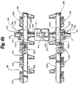
- Fig. 4 is a multiple sheet drawing, Figs. 4a and 4b, depicting a top plan view of the undercarriage of the rail grinding machine in accordance with the present invention;
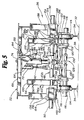
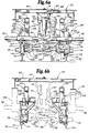
- Fig. 5 is a sectional view taken along 5-5 of Fig. 4a, with grinding modules removed for clarity; Fig. 6a is a sectional view taken along the
line 6a-6a of Fig. 4a with grinding modules removed for clarity; - Fig. 6b is a sectional view along the
line 6b-6b of Fig. 4a, with various parts indicated in phantom lines for clarity; - Fig. 7 is a front elevational view of a grinding module, phantom lines depicting the grinding module in various tilted orientations;
- Fig. 8 is a schematic diagram depicting the grinding pressure control circuit for an individual grinding module;
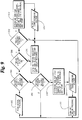
- Fig. 9 is a logic diagram for the grinding pressure control circuit;
- Fig. 10 is a schematic diagram of a railhead, and a single grinding stone placed along the railhead at different positions;
- Fig. 11 is a fragmentary detailed plan view depicting a gimballed pivot pin, taken at the area encircled at 11 in Fig. 4b;
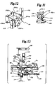
- Fig. 12 is a fragmentary detailed perspective view depicting an undercarriage wheel cowling assembly with elements omitted for clarity; and
- Fig. 13 is a fragmentary, detailed elevation view of Fig. 6a depicting an alternate position of the cowling assembly and undercarriage side frame.
- Referring to the drawings, the
rail grinding machine 20 in accordance with the present invention broadly includes a railroad mountedmain frame 22 supported by railengaging wheels 24, and agrinding undercarriage 26 supported from themain frame 22. Anengine compartment 28 and operator'scab 30 are positioned on themain frame 22. Thegrinding machine 20 is depicted mounted onrailroad track 32 comprisingparallel rails 34 support onroad bed 36 byrailroad ties 38. Fig. 1 depicts therail grinding machine 20 at a road crossing, with therails 34 at a level below the level of the road pavement p, and wood spacers w extending between therails 34. -
Undercarriage 26 broadly includes forward, middle, and rearvertical slide assemblies horizontal slide assemblies Undercarriage 26 is divided into aforward section 52 and arear section 54, with the middlevertical slide assembly 42 and middlehorizontal slide assembly 48 pivotally connecting theforward undercarriage section 52 and therear undercarriage section 54. Forward section right and leftside frame assemblies horizontal slide assembly 46 and the middlehorizontal slide assembly 48, and rear section right andleft side frames horizontal slide assembly 48 and rearhorizontal slide assembly 50. The forward and rearvertical slide assemblies horizontal slide assemblies rear side frames forward undercarriage section 52, the structure and operation of therear undercarriage section 54 can be ascertained from the description of the forward assemblies. - Referring to Fig. 6a, forward
vertical slide assembly 40 broadly includesvertical slide tube 64 fixedly attached tocross beam 66 ofmain frame 22, andvertical slide rod 68 shiftably received withinvertical slide tube 64. U-shaped sliderod end bracket 70 is fixedly attached to the lower end ofvertical slide rod 68. Vertical lift piston andcylinder assembly 72 extends between mainframe cross beam 66 and theU-shaped bracket 70. Fore and aft generallytriangular support brackets frame cross beam 66.Side plate 78 extends betweensupport bracket vertical slide tube 64 byweldments - A
carriage retaining latch 84 is pivotally mounted onside plate 78 atpivot pin 79. Latch actuating piston andcylinder assembly 84 extends between amount 88 on mainframe cross beam 66 and the uppermost end oflatch 84. U-shaped sliderod end bracket 70 comprises identical U-shaped plates mounted on either side ofvertical slide rod 68.Latch rod 90 extends between the two plates ofU-shaped bracket 70, in engageable alignment withlatch 84. - Referring to Fig. 6a, forward
horizontal slide assembly 46 includeshorizontal slide rod 92, and right and lefthorizontal slide tubes horizontal slide rod 92 is pivotally coupled tovertical slide rod 68 bypivot pin 98 received throughU-shaped end bracket 70. Theslide tubes flange plates 99. - Right and left side frames 56, 58 each comprise an uppermost, fore and
aft channel 100 and a plurality of generally equally spaced, downwardly depending grindingmodule support members 102. Referring to Fig. 2, a pair of upper and lower,horizontal frame elements module support members flange plates 99 of right and lefthorizontal slide tubes brackets 107 received byclevises 108 mounted on upper and lowerhorizontal frame elements brackets 107 are retained withinclevises 108 by gimballed pivot pins 109. - Rail engaging
undercarriage wheels 114 are rotatably mounted onindividual hubs 116. Eachhub 116 slideably supportscowling 118. Thecowlings 118 are fixedly attached to respective side frames 56, 58. Shifting of eachcowling 118 axially along itsrespective hub 116, therefore, when its associatedundercarriage wheel 114 is in engagement withrail 34, will shift the respective side frames 56, 58 to which thecowling 118 is attached laterally relative to therail 34. - Each
hub 116 is fixedly connected to a side frame shiftingbrace plate 120. Aguide rod 122 extends from eachbrace plate 120. Eachcowling 118 includes anaperture 119 for shiftably receiving theguide rod 122 of its associatedbrace plate 120. A side frame shifting piston andcylinder assembly 124 is carried by eachbrace plate 120. Thepiston 125 of each side frame shifting piston andcylinder assembly 124 is fixedly, threadably attached to its associatedcowling 118, and thecylinder 126 of each side frame shifting piston andcylinder assembly 124 is fixedly carried by its associatedbrace plate 120. Referring to the phantom lines of Fig. 3, it will be understood that theguide rods 122 are separate from, but not parallel to, the pistons of the side frame shifting piston andcylinder assemblies 124. - Undercarriage spread
assembly 128 extends between opposed, right andleft brace plates 120.Spread assembly 128 includes spreading piston andcylinder assembly 130, and connectingrod 132. Undercarriage shifting piston andcylinder assembly 134 extends betweenbracket 136 mounted on thehorizontal slide rod 92 andbrace plate 120. - Referring to Fig. 5, the middle
vertical slide assembly 42 and the middlehorizontal slide assembly 48 are, in most respects, identical to the forwardvertical slide assembly 40 and forwardhorizontal slide assembly 46 described above, and similar components bear identical numerals in the drawings. Note, however, that, side frames 56, 58 are connected to the middlehorizontal slide rod 92 in a different manner, to be described in detail below, and that thehorizontal slide rod 92 is captured at its outermost ends bybrackets 138 depending downwardly frommain frame 22. - More particularly, the
horizontal slide rod 92 of middlehorizontal slide rod 48 shiftably supportsframe support collars 140. Theframe support collars 140 include fore and aft, opposed, sideframe receiving clevises 142. The side frame downwardly dependingsupport members 102c adjacent the middlehorizontal slide assembly 48 includeapertured brackets 144 received within the framesupport collar clevises 142 and retained by gimballed pivot pins 146. The gimballed pivot pins 146 are similar in construction to gimballed pivot pins 109. - The
horizontal slide rod 92 of the middlehorizontal slide assembly 48 supports main frame, power receiving,interface assemblies 148 that are slidably received withinmain frame brackets 138. Eachinterface assembly 148 includes a plurality of radially extending mountingplates 150 carried by a mountingcollar 152. Front andrear interface panels 154 are carried by thesupport plates 150, and includefriction bearing members 156. - Individual grinding
modules 158 are supported by opposedpivotal mounts module support members 102 of side frames 56, 58. The grindingmodules 158 includebase 164 fixedly carried by the pivotal module supports 160, 162, and grindingassemblies 166 mounted for up and down shifting relative to thebase 164. The grindingmodule base 164 includes upwardly extendingsupport sleeve 168 through which the grindingassemblies 166 are shiftably received. A module lift piston andcylinder assembly 170 extends between the grindingmodule base 164 and the grindingassembly 166 of each grindingmodule 158. A module tilt piston andcylinder assembly 172 extends between eachpivotal module support 160 and arespective support bracket 174. Thesupport brackets 174 are mounted on side framemodule support members 102. - A
pressure control system 175 for positioningindividual grinding assemblies 166 against therailhead 34 with the appropriate grinding force is depicted in schematic form in Fig. 8. The system broadly includes the grindingassembly 166, grinding assembly vertical position sensing andcontrol system 176 and hydraulic fluid flow sensing andcontrol system 178. - The vertical positioning sensing and
control system 176 includesrheostat 180 mounted on module lift piston andcylinder assembly 170. As depicted in Fig. 8, thepiston 182 of lift piston andcylinder assembly 170 includes anelectrical contact 183. The position of thepiston 182 inside thecylinder 184 of lift piston andcylinder assembly 170 is electrically detected by therheostat 180. The grinding assembly vertical positioning sensing andcontrol circuitry 176 further includesservo amp 186, flowcontrol servo valve 188 andvariable displacement pump 190. - Hydraulic fluid flow sensing and
control system 178 is connected to orbitmotor 192 of grindingassembly 166. The hydraulic fluidflow control system 178 includes constantdisplacement gear pump 194 andfluid pressure sensor 196.Computer 198 provides logic control for thepressure control system 174, andreservoir 200 provides a source of hydraulic fluid for thepressure control system 174. - Referring to Fig. 12,
cowling 118 includes opposed, field side and gauge side pillow blocks 202a, 204a and correcting side plates 206a, 208a. Threaded aperture 210a in pillow block 204a receives the piston of side frame shifting piston andcylinder assembly 124. - Referring to Fig. 11, the
gimballed pivot pin 109 includes straight pin 212a received through ball joint 214a. The ball joint 214a is rotatably received withinbracket 107. Cotter pin 216a retains thestraight pin 109 withinclevis 108. - In operation, the
undercarriage 26 is maintained in a raised and locked position when transporting the grindingmachine 20 to a portion of railroad track to be ground. In particular, each of the vertical lift piston andcylinder assemblies 72 for the forward, middle and rear vertical slide assemblies are retracted, lifting theentire undercarriage 26 off of therails 34. Theundercarriage 26 is maintained in a raised position by engagement oflatch 84 withlatch rod 90 of theU-shaped brackets 70. - Upon arrival at a portion of track to be ground,
latch 84 is disengaged fromU-shaped bracket 70 to permit the lowering of theundercarriage 26. The piston andcylinder assemblies 130 ofspread assemblies 128 are slightly retracted such that the distance betweenopposed undercarriage wheels 114 is less than the distance between opposed rails 34. Once theundercarriage 26 has been lowered to a position where theundercarriage wheels 34 are nearly to the level of the top of therails 34, the piston andcylinder assembly 130 ofspread assemblyd 128 is extended, thereby pushing theundercarriage wheels 34 outwardly until the flanges of theundercarriage wheels 114 come into contact with the gauge side of the railhead ofrails 34. The piston and cylinder of piston andcylinder assembly 130 ofspread assembly 128 are thereupon fixed in relative position such that theundercarriage wheels 114 are rigidly maintained in contact with therails 34. - The above described procedure for positioning the
undercarriage wheels 114 into carriage supporting contact withrails 34 assumes that theundercarriage wheels 114 are basically centered about their respective horizontal slide assemblies, and that the portion of track which theundercarriage 26 is being lowered onto is generally straight. The shift piston andcylinder assembly 134 is employed to shift theundercarriage assembly 26 into engaging alignment with therails 34 when either of the above two assumed conditions are not met. In particular, with reference to Figs. 5 or 6a, extension or retraction of wheel base shifting piston andcylinder assembly 134, while at the same time maintaining the piston and cylinder of spread piston andcylinder assembly 130 in fixed relative position, will shiftundercarriage 26 to the left or right respectively alonghorizontal slide rod 92. Since there is an individually actuated wheel base shifting piston andcylinder assembly 130 associated with each of the forward, middle and rearhorizontal slide assemblies undercarriage 26 can be easily manipulated for set down of theundercarriage 26 on a curved portion of the railroad track. The pivotal connection of the side frames 56, 58 to the middlehorizontal slide assembly 48 permits articulation of theundercarriage 26 for positioning of theundercarriage 26 along a curved track. The gimballed pivot pins 109, 146 contribute to the flexibility of theundercarriage 26. - Each end of each
individual side frame modules 158 supported on individual side frames 56, 58 can be shifted laterally across therails 34 by extension and retraction of the side frame shifting piston andcylinder assemblies 124. Referring to Figs. 5 or 6a, with theundercarriage wheels 114 positioned in engaging contact withrails 34 by thespread assembly 128,brace plate 120 is fixed in lateral position relative to therail 34. Extension of the associated side frame shifting piston andcylinder assembly 124 will accordingly shiftcowling 118 axially along thehub 116, such as is depicted in Fig. 13. The side frames 56, 58 are fixedly attached torespective cowlings 118, and are accordingly shifted relative to theundercarriage wheel 114 and therail 34 with which thewheel 114 is engaged. - Referring to Fig. 7, the tilt angle of each
individual grinding module 158 can be adjusted by the extension or retraction of module tilt piston andcylinder assembly 172. As shown in phantom lines in Fig. 7, extension of the module tilt piston andcylinder assembly 172 tilts the grindingmodule 158 to the right, and retraction of the tilt piston andcylinder assembly 172 tilts the grindingmodule 158 to the left. - The grinding stone of each grinding
module 158 is brought into grinding contact withrail 34, once theundercarriage 26 is in engagement with therails 34, by extension of the associated module lift piston andcylinder assembly 170. The amount of metal ground from arail 34 during a single pass of the grinding stone of the grindingmodule 158 along therail 34 is a function of the speed of rotation of the stone and the amount of force with which the stone is held into contact with therail 34. - The ability to lift each individual grinding module with the piston and
cylinder assembly 170, with the ability to tilt each grindingmodule 158 with the tilt piston andcylinder assembly 172, along with the ability to laterally shift each end of eachside frame cylinder assemblies 124, allows theindividual grinding modules 158 to be brought into contact with therail 34 in a variety of angles and alignments, permitting great flexibility in controlling the grinding operation along curves and around obstructions. It will also be appreciated that, because of the single pivot mount of eachhorizontal slide assembly undercarriage 26 will self-align itself parallel to the plane of the track road bed, independently of the orientation of the main frame to the road bed. This is especially significant in banked curves, where the self-aligning, parallel orientation of theundercarriage 26 to the road bed permits the precise and accurate profile grinding of the railheads. The alignment of the undercarriage to the road bed independently of the orientation of themain frame 22 is maintained, notwithstanding the requirement to provide motive force to theundercarriage 26 from themain frame 22, by transmission of motive force to theundercarriage 26 solely throughbrackets 138. Thebrackets 138 provide fore and aft motive forces to thehorizontal slide rod 92 of middlehorizontal slide assembly 48. Up and down and right and left shifting of the power receivinginterface assemblies 148 within thebrackets 138 is freely allowed. - Operation of the module
pressure control system 174 can be understood with reference to Figs. 8-10. Fig. 10 schematically shows a railhead having corrugations with peaks P and valleys V along its surface. It will be appreciated by those skilled in the art that the corrugations depicted in Fig. 10 are grossly exaggerated; in practice, corrugations as small as six-hundredths of an inch (1.524 mm) can cause damage to rolling stock, and therefore must be ground smooth. The corrugations are removed by grinding metal away from the peaks in the corrugation, and by not grinding away metal in the valleys of the corrugations. - Referring to Fig. 8, the grinding stone is pushed into grinding abutment with the
rail 34 by the extension of grinding module lift piston andcylinder assembly 170. The stone is rotated at a constant number of revolutions per minute byorbit motor 192.Orbit motor 192 is in turn rotated by the application of a constant flow of hydraulic fluid to the motor by constantdisplacement gear pump 194. As will be appreciated, maintaining a constant rate of flow of fluid through themotor 192 requires an increase in the pressure of the fluid delivered to theorbit motor 192 as the force with which the grinding stone is brought into contact withrail 34 increases. - Referring to Fig. 10, a grinding stone S is schematicly depicted in a number of sequential positions as the stone S moves along a
rail 34. At position A, the grinding stone is grinding on the front side of a peak P of a corrugation. As the stone S travels from point A to point B, the pressure of the hydraulic fluid delivered toorbit motor 192 to maintain a constant flow of fluid (and thereby a constant rotational speed of the orbit motor 192), will increase. The pressure of the hydraulic fluid will increase because the stone S is held at the same elevation by the module lift piston andcylinder assembly 170 as the grinding stone S is urged across the upward slope of the corrugation peak. The module lift piston andcylinder assembly 170 will maintain the elevation of the grinding stone S until a maximum acceptable pressure is exceeded. Once the maximum acceptable pressure is exceeded, the elevation of the grinding stone S is incrementally raised until the pressure drops to an acceptable level. It will be appreciated that if the pressure of the hydraulic fluid were allowed to exceed an acceptable minimum, excessive stone wear, hydraulic line failure, and general stress of the grinding system would occur. - The grinding stone S is depicted in position B as being at the top of the corrugation peak P. As the grinding stone is urged forward along the downward slope of the corrugation peak, the pressure of the hydraulic supply fluid to orbit
motor 192 will drop. It is not desirable to grind in the low spot, or valley V of the corrugation, since grinding in the valley V of the corrugation will only accentuate, rather than smooth out, the corrugation. The grinding stone S is therefore held in elevation by the grinding module tilt piston andcylinder assembly 172 until the stone S has traveled a predetermined length L, and arrives at location C in Fig. 10. The length L is set to be less than the peak to peak wavelength of the corrugations. Alternatively, when grinding across a gap in therail 34 provided by a cross over point in a switch, the distance L can be preset to a distance just longer than the length of the longest expected gap. - After the grinding stone S has traveled the predetermined length L, the grinding module tilt piston and
cylinder assembly 172 will lower the stone S at a predetermined rate. The descent of the stone will continue until the stone comes into contact with therail 34, at location D, for instance. The pressure of the hydraulic fluid supplied toorbit motor 192 will again increase as the grinding stone S travels along the rising slope of the second peak P in the corrugation. When the pressure of the hydraulic fluid reaches a predetermined maximum (at location E), the stone S will again incrementally adjust upwardly to relieve the pressure to a point below the maximum acceptable pressure. - Fig. 9 is a flow diagram that depicts the logic process executed by
computer 198 to accomplish the above described positioning of the grinding stone S. Atblock 202, the pressure of the hydraulic fluid supplied toorbit motor 192 is determined atfluid pressure sensor 196. The actual pressure of the fluid is compared to a minimum desired pressure atblock 204. If the pressure of the hydraulic fluid is not below the minimum desired pressure, program flow is directed to block 206 where the actual pressure is compared against a maximum desired fluid pressure. If the actual pressure is not greater than a predetermined maximum, program flow is again directed to block 202 where the actual pressure is again determined, and the comparison loop of the actual pressure to the minimum and maximum desired pressures is again entered. - When the actual pressure of the hydraulic fluid delivered to
orbit motor 192 drops below the desired minimum pressure, program flow is directed to block 208. Atblock 208, the program determines whether the most recent below minimum pressure reading is the first or a subsequent below minimum pressure reading in a consecutive series of readings. In particular, program flow is directed to block 210 if the below pressure reading is the first in the series of readings, where a "below pressure" flag is set to indicate that a first below pressure reading has been made. The program, atblock 210, also begins counting off a delay distance that corresponds to the distance L in Fig. 10 through which the grinding stone S is maintained in elevation before the stone is allowed to descend. Program flow is directed fromblock 210 back to block 202 where another pressure reading is obtained from thefluid sensor 196. - When the pressure reading provided by
fluid pressure sensor 196 is a second or subsequent below pressure reading in a series of readings, the "below pressure" flag will have already been set atblock 210, and program flow will proceed fromblock 208 to block 212. Atblock 212, the program will determine whether the delay distance L has been transited by the grinding stone. If the delay distance L has not been covered by the grinding stone S, the program flow will proceed fromblock 212 to block 202 where another reading of the fluid pressure is obtained. When the delay distance L has in fact been covered, the program flow is directed fromblock 212 to block 214 where it is determined how far the most recent actual pressure reading was below the desired minimum pressure. The computer will then determine a downward distance through which the stone S should travel, depending on how far below the desired minimum pressure the most recent actual pressure reading was. The magnitude of the downward distance is greater the greater the actual pressure is below the minimum desired pressure. Program flow is next directed fromblock 214 to block 216 where the computer outputs a signal toservo amp 186 which results inservo valve 188 being operated to lower the grinding module lift piston andcylinder assembly 170. - Program flow is next redirected from
block 216 to block 202 where another pressure reading of the hydraulic fluid delivered to theorbit motor 192 is taken. When the pressure of the hydraulic fluid is above the predetermined desired minimum pressure, but is also above the predetermined maximum pressure, the program flow is directed fromblock 204 to block 206, and subsequently to block 218. Atblock 218 the program determines how far above the desired maximum pressure the actual pressure is and computes a distance through which the grinding stone needs to be lifted to relieve the pressure. The magnitude of the distance the stone is to be lifted becomes greater as the amount the actual pressure is above the maximum desired pressure becomes greater. Program flow is next directed to block 220 where a grinding module lift signal is provided toservo amp 186, resulting in the actuation ofservo valve 188 to raise the grinding module lift piston andcylinder assembly 170. The program flow is next directed fromblock 220 to block 222 where the "below pressure" flag previously set atprogram block 210 is turned off. The program then cycles again to block 202 where yet another reading of pressure of the hydraulic fluid deliveredorbit motor 192 is taken, and the logic cycle begins again.
Claims (6)
- A railroad grinding machine (20) having a main frame (22) supported along rails (34) of a railroad track (32), said machine having a grinding module (158) with a grinding head for grinding one of said rails, motive means (192) operably coupled to said grinding module for powering said grinding head, grinding module positioning means (170) operably coupled to said grinding module for urging said grinding head against said one rail at a grinding pressure, sensing means (196) operably coupled to said motive means for operably sensing said grinding pressure, and controlling means (202, 204, 206, 208, 210, 212, 214, 216, 218, 220, 222, 186) operably coupled to said grinding module positioning means and said sensing means for controlling the position of said grinding module in response to said grinding pressure, said controlling means including means (204, 206) for comparing said grinding pressure to a predetermined value to operate said grinding module positioning means (170) in urging said grinding head towards or away from said rail to increase or decrease said grinding pressure to maintain said grinding pressure at said predetermined value, said machine being characterized in that said controlling means further includes means (210, 212) for delaying said grinding module positioning means (170) in moving said grinding head towards said rail to increase said grinding pressure for a predetermined time after said grinding pressure is determined to be less than said predetermined value.
- A method for grinding a railroad track rail (34), comprising:
operating grinding means (158) at a first orientation in grinding contact with said rail while moving said grinding means along said rail;
monitoring the grinding power expended by said grinding means;
shifting said grinding means to a second orientation along a first path of travel away from said rail when said grinding power exceeds a predetermined maximum;
maintaining said grinding means in said first orientation for a predetermined distance along said rail as said grinding means is moved along said rail when said grinding power is less than a predetermined minimum; and
shifting said grinding means to a third orientation along a second path of travel towards said rail when said grinding means has traveled said predetermined distance along said rail. - The method as claimed in claim 2, said grinding means (158) comprising a grinding wheel operated at a constant rotational speed, said step of monitoring said grinding power comprising monitoring the operating power required to operate said grinding wheel at said constant rotational speed.
- The method as claimed in claim 3, said grinding wheel being rotated at said constant rotational speed by a constant flow hydraulic fluid motive system (192), said step of monitoring said operating power comprising monitoring the fluid pressure within said constant flow hydraulic fluid motive system.
- The method as claimed in claim 2, said step of shifting said grinding means (158) to said second orientation including the step of computing the distance to shift said grinding means to said second orientation along said first path of travel as a function of how much said grinding power exceeds said predetermined maximum.
- The method as claimed in claim 2, said step of shifting said grinding means (158) to said third orientation including the step of computing the distance to shift said grinding means to said third orientation along said second path of travel as a function of how far said grinding power is below said predetermined minimum.
Priority Applications (1)
| Application Number | Priority Date | Filing Date | Title |
|---|---|---|---|
| AT88910229T ATE98722T1 (en) | 1987-10-16 | 1988-10-14 | RAIL GRINDER. |
Applications Claiming Priority (2)
| Application Number | Priority Date | Filing Date | Title |
|---|---|---|---|
| US07/109,542 US4829723A (en) | 1987-10-16 | 1987-10-16 | Rail grinding machine |
| US109542 | 1998-07-02 |
Related Child Applications (2)
| Application Number | Title | Priority Date | Filing Date |
|---|---|---|---|
| EP92116284.8 Division-Into | 1992-09-23 | ||
| EP92116283.0 Division-Into | 1992-09-23 |
Publications (3)
| Publication Number | Publication Date |
|---|---|
| EP0395688A1 EP0395688A1 (en) | 1990-11-07 |
| EP0395688A4 EP0395688A4 (en) | 1991-06-12 |
| EP0395688B1 true EP0395688B1 (en) | 1993-12-15 |
Family
ID=22328221
Family Applications (1)
| Application Number | Title | Priority Date | Filing Date |
|---|---|---|---|
| EP88910229A Expired - Lifetime EP0395688B1 (en) | 1987-10-16 | 1988-10-14 | Rail grinding machine |
Country Status (7)
| Country | Link |
|---|---|
| US (1) | US4829723A (en) |
| EP (1) | EP0395688B1 (en) |
| CN (1) | CN1034236A (en) |
| AU (1) | AU600879B2 (en) |
| CA (1) | CA1299875C (en) |
| DE (1) | DE3886418T2 (en) |
| WO (1) | WO1989003455A1 (en) |
Families Citing this family (16)
| Publication number | Priority date | Publication date | Assignee | Title |
|---|---|---|---|---|
| EP0315704B1 (en) * | 1987-11-07 | 1991-08-07 | Les Fils D'auguste Scheuchzer S.A. | Rail grinding machine for reprofiling railheads |
| US6033166A (en) * | 1998-08-27 | 2000-03-07 | Koppers Industries, Inc. | Rail milling machine |
| US6719616B2 (en) | 2000-09-08 | 2004-04-13 | Loram Maintenance Of Way, Inc. | Rail grinding apparatus |
| ATE450654T1 (en) * | 2001-10-25 | 2009-12-15 | Loram Maintenance Of Way | METHOD AND DEVICE FOR CONTINUOUSLY GRINDING RAILWAY CROSSING AND MAIN TRACKS |
| US7442115B1 (en) | 2003-05-15 | 2008-10-28 | Racine Railroad Products, Inc. | Railway grinder |
| CN102275593B (en) * | 2010-06-11 | 2015-03-04 | 北京铁道工程机电技术研究所有限公司 | Pit type train lifting jack of high-speed multiple unit |
| AT510566B1 (en) * | 2010-11-11 | 2012-05-15 | Linsinger Maschinenbau Gesellschaft M B H | METHOD FOR PROFILING A LAYERED RAIL AND MACHINING VEHICLE |
| CN102501171B (en) * | 2011-11-18 | 2013-11-13 | 北京交通大学 | Gas-liquid driving system |
| DE202017103078U1 (en) * | 2017-05-22 | 2017-06-21 | Robel Bahnbaumaschinen Gmbh | Manually slidable rail grinder on rails of a track |
| CN108755302B (en) * | 2018-07-16 | 2023-12-19 | 兰州理工大学 | For rail end chamfer grinding machine |
| EP3844344A4 (en) | 2018-08-27 | 2022-08-03 | Harsco Technologies LLC | RAIL MILLING VEHICLE |
| CN111188233B (en) * | 2020-03-06 | 2025-01-03 | 唐山昆铁科技有限公司 | Intelligent rail dressing and grinding equipment |
| KR20220067649A (en) | 2020-11-17 | 2022-05-25 | 삼성디스플레이 주식회사 | Display device |
| EP4267798B1 (en) * | 2020-12-22 | 2024-07-31 | Schweerbau International GmbH & Co. KG | Device and method for grinding a profile |
| CN115323845B (en) * | 2022-10-14 | 2023-02-03 | 中国铁建高新装备股份有限公司 | Track grinding control method and device, track grinding vehicle and electronic equipment |
| CN117163102B (en) * | 2023-11-03 | 2024-01-26 | 江苏今创车辆有限公司 | Track detection device with crack automatic positioning function |
Family Cites Families (21)
| Publication number | Priority date | Publication date | Assignee | Title |
|---|---|---|---|---|
| DE1085065B (en) * | 1954-02-18 | 1960-07-07 | Schoerling & Co Waggonbau | Rail grinding device, especially for railroad tracks |
| US2741883A (en) * | 1954-11-19 | 1956-04-17 | Scheuchzer Alfred | Apparatus for rectifying the rails of railroad tracks |
| US3358406A (en) * | 1965-10-14 | 1967-12-19 | Speno International | Rail grinder |
| US3423858A (en) * | 1967-01-10 | 1969-01-28 | Speno International | Automatic control system for railway work apparatus |
| CH463555A (en) * | 1967-08-08 | 1968-10-15 | Speno Internat S A | Railway track deburring machine |
| US3606705A (en) * | 1969-07-30 | 1971-09-21 | Speno International | Rail grinder |
| US3707808A (en) * | 1970-10-05 | 1973-01-02 | Mannix Construction Inc | Rail grinder |
| CH548488A (en) * | 1972-06-08 | 1974-04-30 | Speno International | TRACK RECTIFICATION PROCESS OF A TRACK OF RAILS BY GRINDING ITS ROLLING SURFACE AND DEVICE FOR IMPLEMENTING THIS PROCESS. |
| US4189873A (en) * | 1975-02-25 | 1980-02-26 | Speno International S.A. | Machine for truing the bearing surface of the rails of a railroad track |
| CH592780A5 (en) * | 1976-01-07 | 1977-11-15 | Speno International | |
| CH606616A5 (en) * | 1976-02-18 | 1978-11-15 | Speno International | |
| CH616186A5 (en) * | 1977-11-04 | 1980-03-14 | Scheuchzer Auguste Les Fils D | Machine for grinding railway rails |
| AT366437B (en) * | 1978-02-10 | 1982-04-13 | Plasser Bahnbaumasch Franz | TRACKABLE MACHINE FOR MACHINING THE RAIL HEAD SURFACES |
| AT368220B (en) * | 1979-08-14 | 1982-09-27 | Plasser Bahnbaumasch Franz | MACHINE FOR MACHINING THE RAIL HEAD SURFACE OF AN INSTALLED TRACK |
| AT368219B (en) * | 1980-01-17 | 1982-09-27 | Plasser Bahnbaumasch Franz | METHOD FOR REMOVING IRREGULARITIES ON THE RAIL HEAD SURFACE OF LAYED TRACKS |
| CH626673A5 (en) * | 1980-07-23 | 1981-11-30 | Speno International | |
| CH666068A5 (en) * | 1983-11-16 | 1988-06-30 | Speno International | DEVICE FOR THE CONTINUOUS REPROFILING OF THE MUSHROOM OF AT LEAST ONE RAIL. |
| US4583327A (en) * | 1983-11-25 | 1986-04-22 | Jackson Jordan, Inc. | Rail grinding car |
| CH655528B (en) * | 1984-02-06 | 1986-04-30 | ||
| US4584798A (en) * | 1984-03-29 | 1986-04-29 | Speno Rail Services Co. | Automated railway track maintenance system |
| US4622781A (en) * | 1985-02-19 | 1986-11-18 | Loram Maintenance Of Way, Inc. | Rail grinding machine |
-
1987
- 1987-10-16 US US07/109,542 patent/US4829723A/en not_active Expired - Lifetime
-
1988
- 1988-05-04 CA CA000565895A patent/CA1299875C/en not_active Expired - Lifetime
- 1988-10-14 AU AU23747/88A patent/AU600879B2/en not_active Expired
- 1988-10-14 WO PCT/US1988/003594 patent/WO1989003455A1/en not_active Ceased
- 1988-10-14 EP EP88910229A patent/EP0395688B1/en not_active Expired - Lifetime
- 1988-10-14 DE DE88910229T patent/DE3886418T2/en not_active Expired - Lifetime
- 1988-10-17 CN CN88108451.4A patent/CN1034236A/en active Pending
Also Published As
| Publication number | Publication date |
|---|---|
| CA1299875C (en) | 1992-05-05 |
| AU600879B2 (en) | 1990-08-23 |
| EP0395688A4 (en) | 1991-06-12 |
| WO1989003455A1 (en) | 1989-04-20 |
| DE3886418T2 (en) | 1994-04-07 |
| US4829723A (en) | 1989-05-16 |
| DE3886418D1 (en) | 1994-01-27 |
| EP0395688A1 (en) | 1990-11-07 |
| AU2374788A (en) | 1989-04-20 |
| CN1034236A (en) | 1989-07-26 |
Similar Documents
| Publication | Publication Date | Title |
|---|---|---|
| CA1299875C (en) | Rail grinding machine | |
| EP0304960B1 (en) | Rail grinding machine | |
| US4135332A (en) | Rail grinding machine | |
| US7748789B2 (en) | Pavement profiler | |
| CA1113788A (en) | Mobile machine for removing surface irregularities from rail heads | |
| JP6667143B2 (en) | Tangential grinding machine | |
| US5575709A (en) | Rail grinding machine for grinding rails of a track | |
| FI79738B (en) | KOERBAR SPAORSTOPPNINGS-NIVELERINGS- OCH RIKTMASKIN. | |
| US4583327A (en) | Rail grinding car | |
| JP3188562B2 (en) | Roadbed tamping machine | |
| JPS624482B2 (en) | ||
| CA1125865A (en) | Mobile apparatus for welding studs to rail base plates | |
| GB2121710A (en) | A device for milling rail heads of railway tracks | |
| JPS6352165B2 (en) | ||
| AU702192B2 (en) | A track tamping machine | |
| GB2077821A (en) | A track maintenance machine comprising a tool support for lifting and lining tools | |
| US4622781A (en) | Rail grinding machine | |
| JPH0230801A (en) | Machine for moving track composed of rail and cross tie in cross direction and method for moving track in cross direction by using said machine | |
| JPS624481B2 (en) | ||
| EP0524661A1 (en) | Rail grinding machine | |
| EP0528444A1 (en) | Rail grinding machine | |
| US6981907B1 (en) | High angle grinder | |
| JPS6352166B2 (en) | ||
| GB2039973A (en) | Propelled track bed cleaning machine comprising a lifting unit | |
| JP3978381B2 (en) | Roadbed processing equipment |
Legal Events
| Date | Code | Title | Description |
|---|---|---|---|
| PUAI | Public reference made under article 153(3) epc to a published international application that has entered the european phase |
Free format text: ORIGINAL CODE: 0009012 |
|
| 17P | Request for examination filed |
Effective date: 19900427 |
|
| AK | Designated contracting states |
Kind code of ref document: A1 Designated state(s): AT BE CH DE FR GB IT LI LU NL SE |
|
| A4 | Supplementary search report drawn up and despatched |
Effective date: 19910424 |
|
| AK | Designated contracting states |
Kind code of ref document: A4 Designated state(s): AT BE CH DE FR GB IT LI LU NL SE |
|
| 17Q | First examination report despatched |
Effective date: 19920313 |
|
| GRAA | (expected) grant |
Free format text: ORIGINAL CODE: 0009210 |
|
| AK | Designated contracting states |
Kind code of ref document: B1 Designated state(s): AT BE CH DE FR GB IT LI LU NL SE |
|
| PG25 | Lapsed in a contracting state [announced via postgrant information from national office to epo] |
Ref country code: BE Effective date: 19931215 |
|
| REF | Corresponds to: |
Ref document number: 98722 Country of ref document: AT Date of ref document: 19940115 Kind code of ref document: T |
|
| XX | Miscellaneous (additional remarks) |
Free format text: TEILANMELDUNG 92116283.0 EINGEREICHT AM 14/10/88. |
|
| REF | Corresponds to: |
Ref document number: 3886418 Country of ref document: DE Date of ref document: 19940127 |
|
| ET | Fr: translation filed | ||
| ITF | It: translation for a ep patent filed | ||
| PG25 | Lapsed in a contracting state [announced via postgrant information from national office to epo] |
Ref country code: NL Effective date: 19940330 |
|
| PG25 | Lapsed in a contracting state [announced via postgrant information from national office to epo] |
Ref country code: SE Effective date: 19941015 |
|
| PLBE | No opposition filed within time limit |
Free format text: ORIGINAL CODE: 0009261 |
|
| STAA | Information on the status of an ep patent application or granted ep patent |
Free format text: STATUS: NO OPPOSITION FILED WITHIN TIME LIMIT |
|
| PG25 | Lapsed in a contracting state [announced via postgrant information from national office to epo] |
Ref country code: CH Effective date: 19941031 Ref country code: LI Effective date: 19941031 Ref country code: LU Free format text: LAPSE BECAUSE OF NON-PAYMENT OF DUE FEES Effective date: 19941031 |
|
| 26N | No opposition filed | ||
| EAL | Se: european patent in force in sweden |
Ref document number: 88910229.9 |
|
| REG | Reference to a national code |
Ref country code: CH Ref legal event code: PL |
|
| EUG | Se: european patent has lapsed |
Ref document number: 88910229.9 |
|
| REG | Reference to a national code |
Ref country code: GB Ref legal event code: IF02 |
|
| PGFP | Annual fee paid to national office [announced via postgrant information from national office to epo] |
Ref country code: DE Payment date: 20071011 Year of fee payment: 20 |
|
| PGFP | Annual fee paid to national office [announced via postgrant information from national office to epo] |
Ref country code: AT Payment date: 20071011 Year of fee payment: 20 Ref country code: IT Payment date: 20071026 Year of fee payment: 20 |
|
| PGFP | Annual fee paid to national office [announced via postgrant information from national office to epo] |
Ref country code: GB Payment date: 20071010 Year of fee payment: 20 |
|
| REG | Reference to a national code |
Ref country code: FR Ref legal event code: ST Effective date: 20080630 |
|
| PGFP | Annual fee paid to national office [announced via postgrant information from national office to epo] |
Ref country code: FR Payment date: 20061010 Year of fee payment: 19 |
|
| REG | Reference to a national code |
Ref country code: GB Ref legal event code: PE20 Expiry date: 20081013 |
|
| PG25 | Lapsed in a contracting state [announced via postgrant information from national office to epo] |
Ref country code: FR Free format text: LAPSE BECAUSE OF NON-PAYMENT OF DUE FEES Effective date: 20071031 |
|
| PG25 | Lapsed in a contracting state [announced via postgrant information from national office to epo] |
Ref country code: GB Free format text: LAPSE BECAUSE OF EXPIRATION OF PROTECTION Effective date: 20081013 |