EP0395616A2 - Method for enhanced ion spectra generation and detection in ion mobility spectrometry - Google Patents
Method for enhanced ion spectra generation and detection in ion mobility spectrometry Download PDFInfo
- Publication number
- EP0395616A2 EP0395616A2 EP90870054A EP90870054A EP0395616A2 EP 0395616 A2 EP0395616 A2 EP 0395616A2 EP 90870054 A EP90870054 A EP 90870054A EP 90870054 A EP90870054 A EP 90870054A EP 0395616 A2 EP0395616 A2 EP 0395616A2
- Authority
- EP
- European Patent Office
- Prior art keywords
- cell
- ion
- ions
- ion current
- flow
- Prior art date
- Legal status (The legal status is an assumption and is not a legal conclusion. Google has not performed a legal analysis and makes no representation as to the accuracy of the status listed.)
- Granted
Links
Images

Classifications
-
- G—PHYSICS
- G01—MEASURING; TESTING
- G01N—INVESTIGATING OR ANALYSING MATERIALS BY DETERMINING THEIR CHEMICAL OR PHYSICAL PROPERTIES
- G01N27/00—Investigating or analysing materials by the use of electric, electrochemical, or magnetic means
- G01N27/62—Investigating or analysing materials by the use of electric, electrochemical, or magnetic means by investigating the ionisation of gases, e.g. aerosols; by investigating electric discharges, e.g. emission of cathode
- G01N27/622—Ion mobility spectrometry
Definitions
- the present invention relates to ion mobility spectrometry ("IMS") and more particularly, to a novel method of operating an ion mobility spectrometer apparatus of known construction.
- IMS ion mobility spectrometry
- IMS Ion mobility spectrometry
- the basic apparatus used in the IMS process comprises an analyzer cell, a power supply furnishing accelerating and control voltages to the cell, means for ionizing samples of analyte admitted to the cell and means for determining the times required for the ions of the various substances present in the cell to traverse a specific length of the cell under the influence of an accelerating electric field and against the force of a stream of an inert drift gas flowing through the cell in the direction opposite to that of the electric field.
- the analyzer cell used in this method includes a second ion gate, the exit gate, positioned adjacent the ion detector.
- the exit gate is selectively opened for a short period, usually equal to the open period of the entrance gate, to permit detection of the ions located in the near vicinity of the exit gate at the opening time.
- the opening of the exit gate is delayed from the opening of the entrance gate an amount of time corresponding to the time required for the ions of a particular substance to transit the cell drift region. Thus, only the ions of a particular substance will be detected for each specific delay time. By scanning the delay times, a spectrum of the substances present in the analyte may be developed.
- the method of the referenced patent involves apparatus in which the analyzer cell is provided with both an ion entrance gate and an ion exit gate. Instead of delaying the opening of the exit gate from the opening of the entrance gate, as in the moving second gate method, the entrance gate and the exit gate are opened and closed simultaneously at relatively high frequencies. Such method enables the selective detection of molecules having transit times which are in phase with the gate operating frequency.
- the method of the invention is distinguished from prior operating methods by reversing the function of the shutter grid, a common feature of IMS apparatus.
- the shutter grid is normally biased open to admit ions to the drift region of the IMS cell and then briefly biased closed to establish distinct incremental volumes; these volumes are void of ions and transit the IMS cell with velocities which are characteristic of the constituent substances of the analyte present in the IMS cell.
- the function of the ion entrance gate of the prior analyzer cell is reversed, so that now the gate is normally biased open to admit ions from the cell reaction region to the cell drift region for the major portion of the time. Ions entering the drift region traverse the drift region and are detected to generate a baseline ion current of a steady, relatively high level. Then the ion entrance gate is biased closed a for a brief interval, corresponding to the gate open interval of the prior art, to create an incremental volume in the cell drift region which is void in ions. The void transits the cell drift region, separating in the course thereof into constituent voids having transit times and volumes corresponding to those of the ion populated pulses of the constituents of the prior art.
- Still another object of the invention is to provide a method of operating ion mobility spectrometry apparatus which permits the measurement of total ion current on a continuous basis, thereby eliminating periodic interruptions in service of the apparatus for calibration purposes and permitting more accurate determinations of the concentrations of the constituent substances of an analyte.
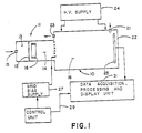
- Fig. 1 is a simplified block diagram of a typical Ion Mobility Spectrometer used in the practice of the method of the invention.
- the spectrometer comprises an analyzer cell 10 of generally cylindrical form, closed at both ends.
- the forward end 11 of the cell may be divided by a permselective membrane 12 into sample chamber 13 and a reaction region 14.
- An analyte sample is admitted to the sample chamber through an inlet 15, often being transported therethrough by a carrier gas.
- the molecules of the analyte sample selectively diffuse through the membrane into the reaction region 14. There the analyte molecules mix with a reactant gas or vapor present in the region to form readily ionizable product molecules.
- reaction region of the cell is divided from the drift region 18 of the cell by a shutter grid 17.
- a steady stream of inert drift gas is flowed through the drift region 14 from an inlet 21, located near the end 22 of the cell, toward a vent 23, located near the shutter grid 17 at the inlet to the drift region.
- a high voltage supply 24 provides a static electric field which is distributed uniformly within the cell along the length of the drift region 18 and which is polarized oppositely to the ions generated within reaction region 14 so as to accelerate ions escaping from the reaction region through the drift region towards the end 22 of the cell.
- An electrometer 25 or other suitable ion current detector is positioned near the end 22 of the cell to detect the ion currents and the arrival times of the ions traversing the drift region of the cell.
- a control circuit controls the operation of a shutter grid bias supply 27 and supplies a synchronizing signal on line 29 to a data acquisition, processing and display unit 31 marking the start of a time base generated therein against which the appearance of ion currents from detector 25 is marked.
- Unit 31 may include means for converting the current outputs of detector 25 to digital form, for storing and processing such signal outputs to enhance the information content and for telemetering or displaying the information in various forms in accordance with known algorithms and processes.
- grid bias supply 27 is pulsed for a brief interval to supply a momentary bias pulse to shutter grid 17, otherwise known as the ion entrance gate, which is of an attractive polarity to the ions in the reaction region 14 of the cell, thereby admitting a small pulse of ions to the cell drift region 18.
- bias supply 27 furnishes a bias voltage to shutter grid 17 which is of repellant polarity to the ions in the reaction region 14 thereby closing off the drift region 18 of the cell from the admission of ions for the major portion of the data acquisition time of the system.
- the polarities of the bias voltage applied to shutter grid 17 by bias supply 27 are reversed from those applied in the methods of the prior art so that instead of applying a momentary bias pulse to the shutter grid of polarity attractive to the ions in the reaction region a momentary bias pulse of repellant polarity is applied, and instead of maintaining the shutter grid biased with a potential which is repellant to the ions of the reaction region for the major portion of the data acquisition time, the shutter grid is biased with a potential which is of an attractive polarity or, at least, passive, permitting the free flow of ions from the reaction region into the drift region for the major portion of the data acquisition time.
- a short void is created in the otherwise free flowing ion stream in the cell drift region.
- This void transits the drift region of the cell and is separated in the course thereof into smaller voids having arrival times at the cell detector which correspond to the arrival times of the constituent ion groups generated by prior methods and creating gaps in the otherwise steady output current of the detector having waveforms which are better defined and have better signal/noise ratios than do the signal waveforms produced by prior methods.
- the improvements afforded by the present invention are evidenced by the representations of oscilloscope displays contained in Figs. 2-6, which were obtained during the tests comparing the method of the present invention with a frequently used method of the prior art.
- Fig. 2 shows the oscilloscope display of signal current obtained from an IMS when a test substance is applied and the shutter grid is biased open for an interval of 0.8 milliseconds during a total scan time of 50 milliseconds.
- the measured signal/noise ratio is approximately 30:1.
- Fig. 3 shows the ion current detected under the same conditions as those of Fig. 2, except that the shutter grid is biased open only for an interval of 0.4 milliseconds.
- the peak ion current 40′ is barely discernable even though the oscilloscope vertical gain has been increased by 2.5 times.
- the measured signal/noise ratio in this case is approximately 2.7:1.
- Fig. 4 is a representation of an oscilloscope display of the ion current detected from an IMS operated in the same manner and under the same conditions as those of Fig. 2 except that here the results of two consecutive scans or operating cycles are presented.
- the time scale of the display is necessarily compressed, but otherwise the ion current waveforms are similar to those of Fig. 2.
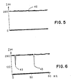
- Fig. 5 is a representation of an oscilloscope display obtained form an IMS when the same test substance and concentration thereof is applied to the IMS as was used in obtaining Fig. 3 and when the shutter grid is biased continuously open.
- the total ion current 42 appears on the screen as a steady line forming an accurate reference against which peak deflections may be measured.
- Fig. 6 is a representation of an oscilloscope display of the ion current from an IMS operated in accordance with the method of the invention.
- the test substance and concentration used in obtaining Fig. 6 was the same as that used in obtaining Figs. 2-4.
- the shutter grid is normally biased open to permit the free flow of ions from the reaction region of the analyzer cell to the drift region of the cell.
- the shutter grid is biased closed for an interval of 0.4 milliseconds and then immediately biased open for the remainder of the scan.
- gap 43 retains a sharp, narrow shape, being broadened only slightly in transiting the cell drift region.
- the ion current waveform of Fig. 4 originally 0.8 milliseconds wide, becomes broadened to approximately 6 milliseconds width in the same course.
- the broadening of the ion current pulse in Fig. 4 is due largely to the mutually repellant Coulomb forces of the ions contained in the pulse, tending to expand and disperse the ion group.
- the improved signal waveforms obtained by practice of the present invention provide increased resolution in the signal waveforms for better identification of the substances contained in an analyte.
- the gate closed interval of 0.4 milliseconds used in obtaining Fig. 6 is to be compared to the gate open interval of 0.4 milliseconds used in obtaining Fig. 3, which provided barely usable data. It is to be expected, therefore, that the method of the invention will provide not only improved resolution but improved signal/noise ratio, as well.
- the data obtained by practice of the invention may be processed, stored and displayed in the same manner as the data obtained by practice of conventional methods.
- the invention is applicable to multiple scan and other signal averaging techniques, and affords the advantage of providing a continuous measurement of total ion current to serve as a reference for calibration purposes.
Abstract
Description
- The present invention relates to ion mobility spectrometry ("IMS") and more particularly, to a novel method of operating an ion mobility spectrometer apparatus of known construction.
- Ion mobility spectrometry (IMS) is an accepted analytical method for determining the identity and concentration of trace substances present in an analyte. The basic apparatus used in the IMS process comprises an analyzer cell, a power supply furnishing accelerating and control voltages to the cell, means for ionizing samples of analyte admitted to the cell and means for determining the times required for the ions of the various substances present in the cell to traverse a specific length of the cell under the influence of an accelerating electric field and against the force of a stream of an inert drift gas flowing through the cell in the direction opposite to that of the electric field.
- U.S. Patent 4,633,083, issued Dec. 30, 1986, describes an Ion Mobility Spectrometer in greater detail and sets forth several conventional methods for operating the apparatus, as well as the method which is unique to the patent. The first of these methods is denominated the single scan method in which the ion entrance gate is opened for a brief period to admit a pulse of ions to the cell drift region. The small ion cloud progresses through the drift region and is separated thereby into constituent ion groups which arrive at the ion detector at different times according to the differences in mass, size and charge of the molecules of each of the groups of the constituents. Observation of the arrival times of the groups at the detector enable the identification of the molecules making up a group and measurement of the ion current resulting from the impingement of a group on the detector permits determination of the concentrations of the substances.
- Another method in the referenced patent is termed the moving second gate method. The analyzer cell used in this method includes a second ion gate, the exit gate, positioned adjacent the ion detector. The exit gate is selectively opened for a short period, usually equal to the open period of the entrance gate, to permit detection of the ions located in the near vicinity of the exit gate at the opening time. The opening of the exit gate is delayed from the opening of the entrance gate an amount of time corresponding to the time required for the ions of a particular substance to transit the cell drift region. Thus, only the ions of a particular substance will be detected for each specific delay time. By scanning the delay times, a spectrum of the substances present in the analyte may be developed.
- The method of the referenced patent involves apparatus in which the analyzer cell is provided with both an ion entrance gate and an ion exit gate. Instead of delaying the opening of the exit gate from the opening of the entrance gate, as in the moving second gate method, the entrance gate and the exit gate are opened and closed simultaneously at relatively high frequencies. Such method enables the selective detection of molecules having transit times which are in phase with the gate operating frequency.
- All of the above-described methods of the prior art have one feature in common; namely, that the bulk of the ions generated in the analyzer cell reaction region are excluded from entering the analyzer cell drift region, or if present in the analyzer cell drift region, the bulk of the ions herein are excluded from detection.
- The method of the invention is distinguished from prior operating methods by reversing the function of the shutter grid, a common feature of IMS apparatus. In accordance with the invention, the shutter grid is normally biased open to admit ions to the drift region of the IMS cell and then briefly biased closed to establish distinct incremental volumes; these volumes are void of ions and transit the IMS cell with velocities which are characteristic of the constituent substances of the analyte present in the IMS cell.
- In accordance with the method of the present invention, the function of the ion entrance gate of the prior analyzer cell is reversed, so that now the gate is normally biased open to admit ions from the cell reaction region to the cell drift region for the major portion of the time. Ions entering the drift region traverse the drift region and are detected to generate a baseline ion current of a steady, relatively high level. Then the ion entrance gate is biased closed a for a brief interval, corresponding to the gate open interval of the prior art, to create an incremental volume in the cell drift region which is void in ions. The void transits the cell drift region, separating in the course thereof into constituent voids having transit times and volumes corresponding to those of the ion populated pulses of the constituents of the prior art. Significant advantages of method of the invention include a substantial improvement in signal to noise ratio as compared to the prior art methods operating under similar conditions; improved signal pulse shape and width as compared to prior art methods under similar conditions; and, the enablement of measurement of the total cell ion current on a continuous basis, thereby permitting a more precise determination of the concentration of the constituents of an analyte.
- Accordingly, it is an object of the present invention to provide a method of operating ion mobility spectrometry apparatus having improved sensitivity for the detection of the constituent substances of an analyte which are low in concentration.
- It is another object of the invention to provide a method of operating ion mobility spectrometry apparatus providing improved resolution of the waveforms of the output signals from such apparatus to enable more accurate determinations of the identities and concentrations of the constituent substances of analyte.
- Still another object of the invention is to provide a method of operating ion mobility spectrometry apparatus which permits the measurement of total ion current on a continuous basis, thereby eliminating periodic interruptions in service of the apparatus for calibration purposes and permitting more accurate determinations of the concentrations of the constituent substances of an analyte.
-
- Fig. 1 is a functional block diagram of an Ion Mobility Spectrometer;
- Fig. 2 is a representation of the oscilloscope display of the detected ion current when an IMS is operated in accordance with a frequently used method of the prior art;
- Fig. 3 is a representation of an oscilloscope display if the detected ion current from an IMS operated in the same manner and under the same conditions as those of Fig. 1 except that the time interval during which the shutter grid is biased has been reduced by one-half;
- Fig. 4 is a representation of an oscilloscope display obtained under the same conditions as those in Fig. 1 showing a double scan presentation of the detected ion current;
- Fig. 5 is a representation of an oscilloscope display of the total ion current detected from an IMS when the shutter grid thereof is biased open continuously; and
- Fig. 6 is a representation of an oscilloscope display of the ion current detected from an IMS operated in accordance with the method of the present invention using the same test substance and concentration thereof as was used to obtain Figs. 2-4.
- Fig. 1 is a simplified block diagram of a typical Ion Mobility Spectrometer used in the practice of the method of the invention. The spectrometer comprises an
analyzer cell 10 of generally cylindrical form, closed at both ends. Theforward end 11 of the cell may be divided by apermselective membrane 12 intosample chamber 13 and areaction region 14. An analyte sample is admitted to the sample chamber through aninlet 15, often being transported therethrough by a carrier gas. The molecules of the analyte sample selectively diffuse through the membrane into thereaction region 14. There the analyte molecules mix with a reactant gas or vapor present in the region to form readily ionizable product molecules. These products molecules are ionized by the emissions of an ionizingsource 16, suitably a ring of radioactive Ni63. The reaction region of the cell is divided from thedrift region 18 of the cell by a shutter grid 17. A steady stream of inert drift gas is flowed through thedrift region 14 from aninlet 21, located near theend 22 of the cell, toward avent 23, located near the shutter grid 17 at the inlet to the drift region. - A
high voltage supply 24 provides a static electric field which is distributed uniformly within the cell along the length of thedrift region 18 and which is polarized oppositely to the ions generated withinreaction region 14 so as to accelerate ions escaping from the reaction region through the drift region towards theend 22 of the cell. Anelectrometer 25 or other suitable ion current detector is positioned near theend 22 of the cell to detect the ion currents and the arrival times of the ions traversing the drift region of the cell. - A control circuit controls the operation of a shutter
grid bias supply 27 and supplies a synchronizing signal online 29 to a data acquisition, processing anddisplay unit 31 marking the start of a time base generated therein against which the appearance of ion currents fromdetector 25 is marked.Unit 31 may include means for converting the current outputs ofdetector 25 to digital form, for storing and processing such signal outputs to enhance the information content and for telemetering or displaying the information in various forms in accordance with known algorithms and processes. - As taught by the methods of the prior art,
grid bias supply 27 is pulsed for a brief interval to supply a momentary bias pulse to shutter grid 17, otherwise known as the ion entrance gate, which is of an attractive polarity to the ions in thereaction region 14 of the cell, thereby admitting a small pulse of ions to thecell drift region 18. At all other times bias supply 27 furnishes a bias voltage to shutter grid 17 which is of repellant polarity to the ions in thereaction region 14 thereby closing off thedrift region 18 of the cell from the admission of ions for the major portion of the data acquisition time of the system. - In the method of the present invention, the polarities of the bias voltage applied to shutter grid 17 by
bias supply 27 are reversed from those applied in the methods of the prior art so that instead of applying a momentary bias pulse to the shutter grid of polarity attractive to the ions in the reaction region a momentary bias pulse of repellant polarity is applied, and instead of maintaining the shutter grid biased with a potential which is repellant to the ions of the reaction region for the major portion of the data acquisition time, the shutter grid is biased with a potential which is of an attractive polarity or, at least, passive, permitting the free flow of ions from the reaction region into the drift region for the major portion of the data acquisition time. Then, instead of admitting a short pulse ions into the cell drift region, a short void is created in the otherwise free flowing ion stream in the cell drift region. This void transits the drift region of the cell and is separated in the course thereof into smaller voids having arrival times at the cell detector which correspond to the arrival times of the constituent ion groups generated by prior methods and creating gaps in the otherwise steady output current of the detector having waveforms which are better defined and have better signal/noise ratios than do the signal waveforms produced by prior methods. The improvements afforded by the present invention are evidenced by the representations of oscilloscope displays contained in Figs. 2-6, which were obtained during the tests comparing the method of the present invention with a frequently used method of the prior art. - Fig. 2 shows the oscilloscope display of signal current obtained from an IMS when a test substance is applied and the shutter grid is biased open for an interval of 0.8 milliseconds during a total scan time of 50 milliseconds. The shutter grid is biased open at t=0 and biased closed at t=0.8 milliseconds. The resultant ion
current peak 40 appears at the detector at approximately t=11 milliseconds and the ion current waveform is approximately 6 milliseconds wide at the base. The measured signal/noise ratio is approximately 30:1. - Fig. 3 shows the ion current detected under the same conditions as those of Fig. 2, except that the shutter grid is biased open only for an interval of 0.4 milliseconds. The
peak ion current 40′ is barely discernable even though the oscilloscope vertical gain has been increased by 2.5 times. The measured signal/noise ratio in this case is approximately 2.7:1. - Fig. 4 is a representation of an oscilloscope display of the ion current detected from an IMS operated in the same manner and under the same conditions as those of Fig. 2 except that here the results of two consecutive scans or operating cycles are presented. The time scale of the display is necessarily compressed, but otherwise the ion current waveforms are similar to those of Fig. 2.
- Fig. 5 is a representation of an oscilloscope display obtained form an IMS when the same test substance and concentration thereof is applied to the IMS as was used in obtaining Fig. 3 and when the shutter grid is biased continuously open. The total ion current 42 appears on the screen as a steady line forming an accurate reference against which peak deflections may be measured.
- Fig. 6 is a representation of an oscilloscope display of the ion current from an IMS operated in accordance with the method of the invention. The test substance and concentration used in obtaining Fig. 6 was the same as that used in obtaining Figs. 2-4. In the present method, the shutter grid is normally biased open to permit the free flow of ions from the reaction region of the analyzer cell to the drift region of the cell. At t=0 the shutter grid is biased closed for an interval of 0.4 milliseconds and then immediately biased open for the remainder of the scan. The void in ion current created by the closed shutter grid progresses through the drift region of the cell and appears at the detector as a sharp, well-defined
gap 43 in ion current at approximately t=10. - Comparing Fig. 4 with Fig. 6, note that
gap 43 retains a sharp, narrow shape, being broadened only slightly in transiting the cell drift region. The ion current waveform of Fig. 4, originally 0.8 milliseconds wide, becomes broadened to approximately 6 milliseconds width in the same course. The broadening of the ion current pulse in Fig. 4 is due largely to the mutually repellant Coulomb forces of the ions contained in the pulse, tending to expand and disperse the ion group. - In the case of Fig. 6, however, the ions bound the void 43 and the same Coulomb forces tending to expand the pulse of Fig. 4 now tend to compress the shape of the void 43. The improved signal waveforms obtained by practice of the present invention provide increased resolution in the signal waveforms for better identification of the substances contained in an analyte.
- Note also that the gate closed interval of 0.4 milliseconds used in obtaining Fig. 6 is to be compared to the gate open interval of 0.4 milliseconds used in obtaining Fig. 3, which provided barely usable data. It is to be expected, therefore, that the method of the invention will provide not only improved resolution but improved signal/noise ratio, as well.
- A theoretical foundation for the method of the invention may be developed from the mathematical theory describing the conventionally operated IMS as published by G.E. Spangler and C.I. Collins, Analytical Chemistry 47, 403 (1975).
- Obviously, the data obtained by practice of the invention may be processed, stored and displayed in the same manner as the data obtained by practice of conventional methods. The invention is applicable to multiple scan and other signal averaging techniques, and affords the advantage of providing a continuous measurement of total ion current to serve as a reference for calibration purposes.
Claims (8)
Applications Claiming Priority (2)
| Application Number | Priority Date | Filing Date | Title |
|---|---|---|---|
| US344128 | 1989-04-27 | ||
| US07/344,128 US4950893A (en) | 1989-04-27 | 1989-04-27 | Method and apparatus for enhanced ion spectra generation and detection in ion mobility spectrometry |
Publications (3)
| Publication Number | Publication Date |
|---|---|
| EP0395616A2 true EP0395616A2 (en) | 1990-10-31 |
| EP0395616A3 EP0395616A3 (en) | 1991-04-17 |
| EP0395616B1 EP0395616B1 (en) | 1994-09-14 |
Family
ID=23349173
Family Applications (1)
| Application Number | Title | Priority Date | Filing Date |
|---|---|---|---|
| EP90870054A Expired - Lifetime EP0395616B1 (en) | 1989-04-27 | 1990-04-11 | Method for enhanced ion spectra generation and detection in ion mobility spectrometry |
Country Status (5)
| Country | Link |
|---|---|
| US (1) | US4950893A (en) |
| EP (1) | EP0395616B1 (en) |
| JP (1) | JP2934903B2 (en) |
| CA (1) | CA2014138C (en) |
| DE (1) | DE69012408T2 (en) |
Families Citing this family (13)
| Publication number | Priority date | Publication date | Assignee | Title |
|---|---|---|---|---|
| GB2217103B (en) * | 1988-04-06 | 1992-09-23 | Graseby Ionics Ltd | Ion mobility detector |
| US5234838A (en) * | 1990-04-17 | 1993-08-10 | Environmental Technologies Group, Inc. | Ammonia monitor based on ion mobility spectrometry with selective dopant chemistry |
| US5032721A (en) * | 1990-06-01 | 1991-07-16 | Environmental Technologies Group, Inc. | Acid gas monitor based on ion mobility spectrometry |
| US5283199A (en) * | 1990-06-01 | 1994-02-01 | Environmental Technologies Group, Inc. | Chlorine dioxide monitor based on ion mobility spectrometry with selective dopant chemistry |
| US5095206A (en) * | 1990-06-01 | 1992-03-10 | Environmental Technologies Group, Inc. | Method and apparatus for improving the specificity of an ion mobility spectrometer utillizing sulfur dioxide dopant chemistry |
| US5189301A (en) * | 1991-08-20 | 1993-02-23 | Cpad Holdings, Ltd. | Simple compact ion mobility spectrometer having a focusing electrode which defines a non-uniform field for the drift region |
| US5184015A (en) * | 1991-09-27 | 1993-02-02 | Martin Marietta Energy Systems, Inc. | Charged particle mobility refrigerant analyzer |
| US7078680B1 (en) | 2004-02-06 | 2006-07-18 | The United States Of America As Represented By The Secretary Of The Navy | Ion mobility spectrometer using ion beam modulation and wavelet decomposition |
| US7985949B2 (en) * | 2007-07-30 | 2011-07-26 | Particle Measuring Systems, Inc. | Detection of analytes using ion mobility spectrometry |
| CN101587815B (en) * | 2008-05-19 | 2011-12-21 | 同方威视技术股份有限公司 | Double-sided ion source |
| CN103972020A (en) * | 2013-01-31 | 2014-08-06 | 中国科学院大连化学物理研究所 | Analytical method for ion mobility spectrometry |
| CN103245715A (en) * | 2013-05-17 | 2013-08-14 | 中国农业科学院农业质量标准与检测技术研究所 | Method for detecting clenbuterol hydrochloride in sample in assisted mode based on ion mobility spectrometry |
| US10126265B2 (en) * | 2016-03-02 | 2018-11-13 | Washington State University | Perturbation ion mobility mass spectrometry and the method of measuring ion mobility of selected ions |
Citations (4)
| Publication number | Priority date | Publication date | Assignee | Title |
|---|---|---|---|---|
| US2810075A (en) * | 1954-02-08 | 1957-10-15 | Cons Electrodynamics Corp | Mass spectrometry |
| US3522425A (en) * | 1967-11-28 | 1970-08-04 | Gen Electric | Apparatus for selective separation of ions of different mobilities in a gas stream |
| US3626182A (en) * | 1969-04-01 | 1971-12-07 | Franklin Gnd Corp | Apparatus and method for improving the sensitivity of time of flight ion analysis by ion bunching |
| US4119851A (en) * | 1977-06-23 | 1978-10-10 | Honeywell Inc. | Apparatus and a method for detecting and measuring trace gases in air or other gas backgrounds |
Family Cites Families (1)
| Publication number | Priority date | Publication date | Assignee | Title |
|---|---|---|---|---|
| US4633083A (en) * | 1985-04-08 | 1986-12-30 | Washington State University Research Foundation, Inc. | Chemical analysis by time dispersive ion spectrometry |
-
1989
- 1989-04-27 US US07/344,128 patent/US4950893A/en not_active Expired - Lifetime
-
1990
- 1990-04-09 CA CA002014138A patent/CA2014138C/en not_active Expired - Lifetime
- 1990-04-11 DE DE69012408T patent/DE69012408T2/en not_active Expired - Fee Related
- 1990-04-11 EP EP90870054A patent/EP0395616B1/en not_active Expired - Lifetime
- 1990-04-17 JP JP10153890A patent/JP2934903B2/en not_active Expired - Fee Related
Patent Citations (4)
| Publication number | Priority date | Publication date | Assignee | Title |
|---|---|---|---|---|
| US2810075A (en) * | 1954-02-08 | 1957-10-15 | Cons Electrodynamics Corp | Mass spectrometry |
| US3522425A (en) * | 1967-11-28 | 1970-08-04 | Gen Electric | Apparatus for selective separation of ions of different mobilities in a gas stream |
| US3626182A (en) * | 1969-04-01 | 1971-12-07 | Franklin Gnd Corp | Apparatus and method for improving the sensitivity of time of flight ion analysis by ion bunching |
| US4119851A (en) * | 1977-06-23 | 1978-10-10 | Honeywell Inc. | Apparatus and a method for detecting and measuring trace gases in air or other gas backgrounds |
Also Published As
| Publication number | Publication date |
|---|---|
| CA2014138C (en) | 2000-06-20 |
| DE69012408D1 (en) | 1994-10-20 |
| JP2934903B2 (en) | 1999-08-16 |
| DE69012408T2 (en) | 1995-02-09 |
| CA2014138A1 (en) | 1990-10-27 |
| EP0395616A3 (en) | 1991-04-17 |
| US4950893A (en) | 1990-08-21 |
| JPH03179253A (en) | 1991-08-05 |
| EP0395616B1 (en) | 1994-09-14 |
Similar Documents
| Publication | Publication Date | Title |
|---|---|---|
| US4633083A (en) | Chemical analysis by time dispersive ion spectrometry | |
| US4950893A (en) | Method and apparatus for enhanced ion spectra generation and detection in ion mobility spectrometry | |
| US8610057B2 (en) | Ion selection apparatus and method | |
| US5394092A (en) | System for identifying and quantifying selected constituents of gas samples using selective photoionization | |
| US3742212A (en) | Method and apparatus for pulsed ion cyclotron resonance spectroscopy | |
| US5107109A (en) | Method of increasing the dynamic range and sensitivity of a quadrupole ion trap mass spectrometer | |
| US7538320B2 (en) | Ion detection device and method with compressing ion-beam shutter | |
| US5304797A (en) | Gas analyzer for determining impurity concentration of highly-purified gas | |
| US3254209A (en) | Method and apparatus for increasing the ionization of impurity ions in a mass spectrometer | |
| US6580068B1 (en) | Method and apparatus for time dispersive spectroscopy | |
| Kwantwi-Barima et al. | Increased ion throughput using tristate ion-gate multiplexing | |
| US4464570A (en) | Method for ion cyclotron resonance spectroscopy | |
| US3626182A (en) | Apparatus and method for improving the sensitivity of time of flight ion analysis by ion bunching | |
| Norris et al. | Elimination of aliasing in LA-ICP-MS by alignment of laser and mass spectrometer | |
| Kogan et al. | A portable mass spectrometer for direct monitoring of gases and volatile compounds in air and water samples | |
| US4682027A (en) | Method and apparatus for sample confirmation in gas chromatography | |
| US3582648A (en) | Electron impact time of flight spectrometer | |
| Halas et al. | An inexpensive device for digital measurements of isotopic ratios | |
| McDaniel | Possible Sources of Large Error in Determinations of Ion–Molecule Reaction Rates with Drift Tube–Mass Spectrometers | |
| US6787762B2 (en) | Time dispersive spectrometer using digital switching means | |
| JP2644920B2 (en) | Liquid chromatograph mass spectrometer and analytical method | |
| JP2000082439A (en) | Time-of-flight mass spectrometer | |
| CN210897193U (en) | Ion signal detection device for quadrupole rod mass analyzer | |
| US3522430A (en) | Method and apparatus for maintaining constant the effective ionization energy in a mass spectrometer | |
| SU1105962A1 (en) | Mass-spectrometric method of analyzing solids |
Legal Events
| Date | Code | Title | Description |
|---|---|---|---|
| PUAI | Public reference made under article 153(3) epc to a published international application that has entered the european phase |
Free format text: ORIGINAL CODE: 0009012 |
|
| AK | Designated contracting states |
Kind code of ref document: A2 Designated state(s): CH DE FR GB IT LI |
|
| PUAL | Search report despatched |
Free format text: ORIGINAL CODE: 0009013 |
|
| AK | Designated contracting states |
Kind code of ref document: A3 Designated state(s): CH DE FR GB IT LI |
|
| 17P | Request for examination filed |
Effective date: 19911010 |
|
| 17Q | First examination report despatched |
Effective date: 19930623 |
|
| GRAA | (expected) grant |
Free format text: ORIGINAL CODE: 0009210 |
|
| AK | Designated contracting states |
Kind code of ref document: B1 Designated state(s): CH DE FR GB IT LI |
|
| ITF | It: translation for a ep patent filed |
Owner name: STUDIO GLP S.R.L. |
|
| REF | Corresponds to: |
Ref document number: 69012408 Country of ref document: DE Date of ref document: 19941020 |
|
| ET | Fr: translation filed | ||
| PLBE | No opposition filed within time limit |
Free format text: ORIGINAL CODE: 0009261 |
|
| STAA | Information on the status of an ep patent application or granted ep patent |
Free format text: STATUS: NO OPPOSITION FILED WITHIN TIME LIMIT |
|
| 26N | No opposition filed | ||
| REG | Reference to a national code |
Ref country code: GB Ref legal event code: IF02 |
|
| PGFP | Annual fee paid to national office [announced via postgrant information from national office to epo] |
Ref country code: IT Payment date: 20060430 Year of fee payment: 17 |
|
| PGFP | Annual fee paid to national office [announced via postgrant information from national office to epo] |
Ref country code: DE Payment date: 20080417 Year of fee payment: 19 Ref country code: CH Payment date: 20080415 Year of fee payment: 19 Ref country code: FR Payment date: 20080312 Year of fee payment: 19 |
|
| PGFP | Annual fee paid to national office [announced via postgrant information from national office to epo] |
Ref country code: GB Payment date: 20080416 Year of fee payment: 19 |
|
| PG25 | Lapsed in a contracting state [announced via postgrant information from national office to epo] |
Ref country code: IT Free format text: LAPSE BECAUSE OF NON-PAYMENT OF DUE FEES Effective date: 20070411 |
|
| REG | Reference to a national code |
Ref country code: CH Ref legal event code: PL |
|
| GBPC | Gb: european patent ceased through non-payment of renewal fee |
Effective date: 20090411 |
|
| REG | Reference to a national code |
Ref country code: FR Ref legal event code: ST Effective date: 20091231 |
|
| PG25 | Lapsed in a contracting state [announced via postgrant information from national office to epo] |
Ref country code: CH Free format text: LAPSE BECAUSE OF NON-PAYMENT OF DUE FEES Effective date: 20090430 Ref country code: DE Free format text: LAPSE BECAUSE OF NON-PAYMENT OF DUE FEES Effective date: 20091103 Ref country code: LI Free format text: LAPSE BECAUSE OF NON-PAYMENT OF DUE FEES Effective date: 20090430 |
|
| PG25 | Lapsed in a contracting state [announced via postgrant information from national office to epo] |
Ref country code: FR Free format text: LAPSE BECAUSE OF NON-PAYMENT OF DUE FEES Effective date: 20091222 Ref country code: GB Free format text: LAPSE BECAUSE OF NON-PAYMENT OF DUE FEES Effective date: 20090411 |