EP0395461A1 - Vacuum-assisted servo motor - Google Patents
Vacuum-assisted servo motor Download PDFInfo
- Publication number
- EP0395461A1 EP0395461A1 EP90400853A EP90400853A EP0395461A1 EP 0395461 A1 EP0395461 A1 EP 0395461A1 EP 90400853 A EP90400853 A EP 90400853A EP 90400853 A EP90400853 A EP 90400853A EP 0395461 A1 EP0395461 A1 EP 0395461A1
- Authority
- EP
- European Patent Office
- Prior art keywords
- chamber
- auxiliary
- housing
- piston
- booster according
- Prior art date
- Legal status (The legal status is an assumption and is not a legal conclusion. Google has not performed a legal analysis and makes no representation as to the accuracy of the status listed.)
- Granted
Links
- 230000000284 resting effect Effects 0.000 claims abstract description 5
- 239000012528 membrane Substances 0.000 claims description 9
- 230000003213 activating effect Effects 0.000 abstract 1
- 230000001965 increasing effect Effects 0.000 description 4
- 230000006835 compression Effects 0.000 description 2
- 238000007906 compression Methods 0.000 description 2
- 230000005284 excitation Effects 0.000 description 2
- 238000001514 detection method Methods 0.000 description 1
- 238000006073 displacement reaction Methods 0.000 description 1
- 230000001939 inductive effect Effects 0.000 description 1
- 230000014759 maintenance of location Effects 0.000 description 1
- 238000012986 modification Methods 0.000 description 1
- 230000004048 modification Effects 0.000 description 1
Images


Classifications
-
- B—PERFORMING OPERATIONS; TRANSPORTING
- B60—VEHICLES IN GENERAL
- B60T—VEHICLE BRAKE CONTROL SYSTEMS OR PARTS THEREOF; BRAKE CONTROL SYSTEMS OR PARTS THEREOF, IN GENERAL; ARRANGEMENT OF BRAKING ELEMENTS ON VEHICLES IN GENERAL; PORTABLE DEVICES FOR PREVENTING UNWANTED MOVEMENT OF VEHICLES; VEHICLE MODIFICATIONS TO FACILITATE COOLING OF BRAKES
- B60T13/00—Transmitting braking action from initiating means to ultimate brake actuator with power assistance or drive; Brake systems incorporating such transmitting means, e.g. air-pressure brake systems
- B60T13/10—Transmitting braking action from initiating means to ultimate brake actuator with power assistance or drive; Brake systems incorporating such transmitting means, e.g. air-pressure brake systems with fluid assistance, drive, or release
- B60T13/24—Transmitting braking action from initiating means to ultimate brake actuator with power assistance or drive; Brake systems incorporating such transmitting means, e.g. air-pressure brake systems with fluid assistance, drive, or release the fluid being gaseous
- B60T13/46—Vacuum systems
- B60T13/52—Vacuum systems indirect, i.e. vacuum booster units
- B60T13/563—Vacuum systems indirect, i.e. vacuum booster units with multiple booster units, e.g. tandem booster units
-
- B—PERFORMING OPERATIONS; TRANSPORTING
- B60—VEHICLES IN GENERAL
- B60T—VEHICLE BRAKE CONTROL SYSTEMS OR PARTS THEREOF; BRAKE CONTROL SYSTEMS OR PARTS THEREOF, IN GENERAL; ARRANGEMENT OF BRAKING ELEMENTS ON VEHICLES IN GENERAL; PORTABLE DEVICES FOR PREVENTING UNWANTED MOVEMENT OF VEHICLES; VEHICLE MODIFICATIONS TO FACILITATE COOLING OF BRAKES
- B60T13/00—Transmitting braking action from initiating means to ultimate brake actuator with power assistance or drive; Brake systems incorporating such transmitting means, e.g. air-pressure brake systems
- B60T13/10—Transmitting braking action from initiating means to ultimate brake actuator with power assistance or drive; Brake systems incorporating such transmitting means, e.g. air-pressure brake systems with fluid assistance, drive, or release
- B60T13/24—Transmitting braking action from initiating means to ultimate brake actuator with power assistance or drive; Brake systems incorporating such transmitting means, e.g. air-pressure brake systems with fluid assistance, drive, or release the fluid being gaseous
- B60T13/46—Vacuum systems
- B60T13/52—Vacuum systems indirect, i.e. vacuum booster units
- B60T13/567—Vacuum systems indirect, i.e. vacuum booster units characterised by constructional features of the casing or by its strengthening or mounting arrangements
- B60T13/5675—Supportstruts
-
- B—PERFORMING OPERATIONS; TRANSPORTING
- B60—VEHICLES IN GENERAL
- B60T—VEHICLE BRAKE CONTROL SYSTEMS OR PARTS THEREOF; BRAKE CONTROL SYSTEMS OR PARTS THEREOF, IN GENERAL; ARRANGEMENT OF BRAKING ELEMENTS ON VEHICLES IN GENERAL; PORTABLE DEVICES FOR PREVENTING UNWANTED MOVEMENT OF VEHICLES; VEHICLE MODIFICATIONS TO FACILITATE COOLING OF BRAKES
- B60T13/00—Transmitting braking action from initiating means to ultimate brake actuator with power assistance or drive; Brake systems incorporating such transmitting means, e.g. air-pressure brake systems
- B60T13/10—Transmitting braking action from initiating means to ultimate brake actuator with power assistance or drive; Brake systems incorporating such transmitting means, e.g. air-pressure brake systems with fluid assistance, drive, or release
- B60T13/24—Transmitting braking action from initiating means to ultimate brake actuator with power assistance or drive; Brake systems incorporating such transmitting means, e.g. air-pressure brake systems with fluid assistance, drive, or release the fluid being gaseous
- B60T13/46—Vacuum systems
- B60T13/52—Vacuum systems indirect, i.e. vacuum booster units
- B60T13/569—Vacuum systems indirect, i.e. vacuum booster units characterised by piston details, e.g. construction, mounting of diaphragm
-
- B—PERFORMING OPERATIONS; TRANSPORTING
- B60—VEHICLES IN GENERAL
- B60T—VEHICLE BRAKE CONTROL SYSTEMS OR PARTS THEREOF; BRAKE CONTROL SYSTEMS OR PARTS THEREOF, IN GENERAL; ARRANGEMENT OF BRAKING ELEMENTS ON VEHICLES IN GENERAL; PORTABLE DEVICES FOR PREVENTING UNWANTED MOVEMENT OF VEHICLES; VEHICLE MODIFICATIONS TO FACILITATE COOLING OF BRAKES
- B60T13/00—Transmitting braking action from initiating means to ultimate brake actuator with power assistance or drive; Brake systems incorporating such transmitting means, e.g. air-pressure brake systems
- B60T13/10—Transmitting braking action from initiating means to ultimate brake actuator with power assistance or drive; Brake systems incorporating such transmitting means, e.g. air-pressure brake systems with fluid assistance, drive, or release
- B60T13/66—Electrical control in fluid-pressure brake systems
- B60T13/72—Electrical control in fluid-pressure brake systems in vacuum systems or vacuum booster units
Definitions
- the present invention relates to vacuum actuators designed to apply an additional force to an output member when a force is applied to an input member resting on the output member. and / or to apply a force to an output member following a signal emitted by a device external to the booster.
- Such servomotors are used on motor vehicles in particular to provide braking assistance.
- such a vacuum booster comprises a main housing divided internally in a sealed manner into first and second chambers by a flexible membrane resting on a rigid disc secured to an actuating piston.
- the first chamber is subjected to a low pressure while the second chamber is subjected either to this low pressure when the booster is at rest, or to a higher pressure when the booster is in operation.
- the assistance requested being obtained then either by connecting the first chamber to a source of greater vacuum than the usual source, or by subjecting the second chamber to a pressure greater than the atmospheric pressure.
- an auxiliary pump is required, which significantly increases the total cost price of the assistance device.
- the object of the present invention is to obviate this drawback by increasing the effective area of the actuating disc of a servomotor without increasing the external diametrical size.
- the present invention also makes it possible to produce a booster having this function.
- At least one auxiliary housing is integral with the rigid disc and protrudes in the first chamber, an auxiliary piston internally sealingly dividing the auxiliary housing into third and fourth chambers, the third chamber being closed. by the rigid disc and the auxiliary piston being mounted fixed relative to the main housing.
- the auxiliary housing and the auxiliary piston are annular.
- the auxiliary piston is mounted fixed relative to the main housing by means of at least one rigid rod successively passing through the third chamber, the rigid disc and possibly the membrane, the rod having one end resting on the main unit in the second bedroom.
- this rod is hollow, it can also ensure communication between the second and fourth chambers.
- the auxiliary piston is mounted fixed relative to the main housing by means of at least one rigid rod successively passing through a wall of the auxiliary housing and the first chamber, one end of the rigid rod being firmly fixed to the housing main in the first chamber while the other end of the rod is fixed firmly to the auxiliary piston.
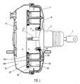
- the booster comprises an input member 1 for example connected to the brake pedal (not shown) of the motor vehicle thus equipped, and an output member 2 bearing on the piston of a master- cylinder (not shown) in the above example.
- the outlet member 2 is supported on the inlet member 1 and on an actuating piston 3.
- This actuating piston is integral with a rigid actuating disc 7 on which rests an unwinding membrane 9 sealingly dividing the housing 12 into two chambers 10 and
- the chamber 10, or first chamber is subjected to a low pressure, the source of vacuum being generally controlled by the heat engine.
- the chamber 20, or second chamber is subjected, at rest to the same low pressure as the chamber 10.
- a displacement of the inlet member 1 causes the closure of a communication orifice between the chambers 10 and 20 and the opening of an orifice putting air at atmospheric pressure into communication with chamber 20; this well-known valve, housed in the tail 5 of the booster has not been shown.
- an auxiliary annular housing 25 is fixed in the first chamber 10 to the rigid disc 7.
- An annular piston 27 internally divides this auxiliary housing 25 into two other chambers 30 and 40 in a sealed manner thanks to an auxiliary unwinding membrane 29 .
- Ports 32 connect the first chamber 10 and the third chamber 30 which is isolated from the second chamber 20 by the rigid disc 7.
- the second and fourth chambers 20, 40 communicate with each other.
- the useful surface on which the pressure difference is exerted is now determined by the section of the main housing 12 to which is added the section of the auxiliary housing.
- a servomotor is thus obtained having a virtual diameter significantly greater than its actual diameter.
- the annular piston 27 is mounted fixed relative to the wall of the second chamber 20 of the housing 12. At least one hollow rod 50 is on the one hand bearing against this wall and on the other hand integral with the annular piston 27 allowing the connecting the second and fourth chambers 20.40 through an orifice made in this annular piston 27.
- the hollow rod 50 therefore passes successively and in leaktight manner, the third chamber 30, the rigid disc 7 and the main membrane 9.
- FIG. 2 A particularly advantageous embodiment is illustrated schematically and partially in Figure 2.
- a mounting key 74 having an end in the form of a conical point projecting into the second chamber 20 is fixed to the housing 12 opposite the hollow rod 50.
- the assembly of the assembly is then made extremely easy.
- the piston 27 is pushed together with the hollow rod 50.
- the latter then impales itself in a non-leaktight manner on the key 74, a means of snap-fitting 70 being provided to prevent any further movement of the auxiliary piston 27 relative to the housing 12.
- the disc 7 has a conventional frustoconical shape, and a wall of the auxiliary housing 25 is directly constituted by a part of the piston 3.
- the fixed retention of the auxiliary piston 27 relative to the wall of the second chamber 20 of the housing 12 is ensured by the resulting force, ie the difference in pressures applied between the chambers 30 and 40 when the booster is active, either from the compression force of a spring 60 when the latter is at rest, or active at the start of the race.
- the compression of the spring 60 results from the fact that when the servomotor is at rest, the spring 65 has a sufficient residual compressive force to push the rigid disc 7 into abutment and compress the spring (s) 60. A difference between free length and compressed length of a few millimeters of the spring 60 sufficient to perform the required function.
- the annular piston 27 is secured to the end of at least one rod 50, the other end of which is secured to the wall of the first chamber 10 of the main housing 12.
- the communication between the second and fourth chambers 20.40 is obtained by means of an elastic bellows 57 disposed in the third chamber 30, one end of which is fixed to the flexible membrane 9 and the other to an orifice made in the annular piston 27.
- the rigid rod passes through a wall of the annular housing 25 in a sealed manner, a seal being provided for this purpose.
- the word “annular” to designate the shape of the auxiliary housing and of the corresponding piston refers to the conventional substantially cylindrical shape of the shell of the main housing.
- annular is meant any possible shape, whether this is an annular shape proper or, for example an oval shape, which allows the output member to project into the center of the booster.
- the auxiliary box can also be constituted by a plurality of boxes of reduced dimensions.
- the rigid disc can have a frustoconical shape.
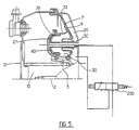
- the first and third chambers When it is desired to use such a servomotor in a traction control device, the first and third chambers must, of course, always communicate.
- the direct communication between the second and fourth chambers can advantageously be eliminated, the fourth chamber then being connected, by means of a pipe and a solenoid valve 200 to the second chamber or to a source of air at atmospheric pressure.
- the difference in pressures that can occur between the third and fourth chambers is then sufficient to move the output member 2 independently of an action on the brake pedal, the detection of an imminent slippage of the drive wheels by a computer. appropriate inducing the emission by this computer of an excitation signal from the solenoid valve 200 which then establishes direct communication from the chamber 40 with atmospheric air.
- the servomotor behaves like a servomotor as described above.
- the auxiliary chamber 40 can be placed in communication with a suitable pressurized air source present on the vehicle, by means of a solenoid valve, or else through a valve, such as that described in the document FR -A-2 334 862.
Landscapes
- Engineering & Computer Science (AREA)
- Transportation (AREA)
- Mechanical Engineering (AREA)
- Braking Systems And Boosters (AREA)
- Actuator (AREA)
- Connection Of Motors, Electrical Generators, Mechanical Devices, And The Like (AREA)
- Braking Arrangements (AREA)
Abstract
Description
La présente invention concerne les servomoteurs à dépression conçus pour appliquer une force additionnelle à un organe de sortie lorsqu'une force est appliquée à un organe d'entrée s'appuyant sur l'organe de sortie. et/ou pour appliquer une force à un organe de sortie consécutivement à un signal émis par un dispositif externe au servomoteur. De tels servomoteurs sont utilisés sur les véhicules automobiles notamment pour assurer une assistance au freinage.The present invention relates to vacuum actuators designed to apply an additional force to an output member when a force is applied to an input member resting on the output member. and / or to apply a force to an output member following a signal emitted by a device external to the booster. Such servomotors are used on motor vehicles in particular to provide braking assistance.
De façon classique, un tel servomoteur à dépression comprend un boîtier principal divisé intérieurement de manière étanche en des première et deuxième chambres par une membrane souple s'appuyant sur un disque rigide solidaire d'un piston d'actionnement. La première chambre est soumise à une basse pression tandis que la deuxième chambre est soumise soit à cette basse pression lorsque le servomoteur est au repos, soit à une pression supérieure lorsque le servomoteur est en fonctionnement.Conventionally, such a vacuum booster comprises a main housing divided internally in a sealed manner into first and second chambers by a flexible membrane resting on a rigid disc secured to an actuating piston. The first chamber is subjected to a low pressure while the second chamber is subjected either to this low pressure when the booster is at rest, or to a higher pressure when the booster is in operation.
Ces servomoteurs présentent une taille importante croissante avec l'assistance requise. Or le compartiment moteur des véhicules automobiles actuels est extrêmement rempli et il est quelquefois impossible de disposer dans ce compartiment un servomoteur dont le diamètre extérieur correspond à la puissance d'assistance demandée par le constructeur.These servomotors are of increasing size with the assistance required. However, the engine compartment of current motor vehicles is extremely full and it is sometimes impossible to have in this compartment a booster whose outside diameter corresponds to the assistance power requested by the manufacturer.
De ce fait, certains constructeurs utilisent un servomoteur de petites dimensions, l'assistance demandée étant obtenue alors soit en connectant la première chambre à une source de dépression plus importante que la source habituelle, soit en soumettant la deuxième chambre à une pression supérieure à la pression atmosphérique. Dans tous les cas, une pompe auxiliaire est requise, ce qui augmente sensiblement le prix de revient total du dispositif d'assistance.As a result, some manufacturers use a small-sized servomotor, the assistance requested being obtained then either by connecting the first chamber to a source of greater vacuum than the usual source, or by subjecting the second chamber to a pressure greater than the atmospheric pressure. In all cases, an auxiliary pump is required, which significantly increases the total cost price of the assistance device.
La présente invention a pour but d'obvier à cet inconvénient en augmentant l'aire effective du disque d'actionnement d'un servomoteur sans augmenter l'encombrement diamétral externe.The object of the present invention is to obviate this drawback by increasing the effective area of the actuating disc of a servomotor without increasing the external diametrical size.
Par ailleurs, il est souhaitable quelquefois, notamment pour éviter le patinage des roues motrices, que ces dernières soient freinées indépendamment d'une action exercée sur la pédale par le conducteur. La présente invention permet également de réaliser un servomoteur présentant cette fonction.Furthermore, it is sometimes desirable, in particular to avoid slipping of the drive wheels, that the latter be braked independently of an action exerted on the pedal by the driver. The present invention also makes it possible to produce a booster having this function.
Pour ce faire, selon l'invention, au moins un boîtier auxiliaire est solidaire du disque rigide et fait saillie dans la première chambre, un piston auxiliaire divisant intérieurement de manière étanche le boîtier auxiliaire en des troisième et quatrième chambres, la troisième chambre étant fermée par le disque rigide et le piston auxiliaire étant monté fixe par rapport au boîtier principal.To do this, according to the invention, at least one auxiliary housing is integral with the rigid disc and protrudes in the first chamber, an auxiliary piston internally sealingly dividing the auxiliary housing into third and fourth chambers, the third chamber being closed. by the rigid disc and the auxiliary piston being mounted fixed relative to the main housing.
De préférence, le boîtier auxiliaire et le piston auxiliaire sont annulaires.Preferably, the auxiliary housing and the auxiliary piston are annular.
Selon un premier mode de réalisation, le piston auxiliaire est monté fixe par rapport au boîtier principal au moyen d'au moins une tige rigide traversant successivement la troisième chambre, le disque rigide et éventuellement la membrane, la tige ayant une extrémité en appui sur le boîtier principal dans la deuxième chambre. Lorsque cette tige est creuse, elle peut assurer en outre la communication entre les deuxième et quatrième chambres.According to a first embodiment, the auxiliary piston is mounted fixed relative to the main housing by means of at least one rigid rod successively passing through the third chamber, the rigid disc and possibly the membrane, the rod having one end resting on the main unit in the second bedroom. When this rod is hollow, it can also ensure communication between the second and fourth chambers.
Selon un autre mode de réalisation, le piston auxiliaire est monté fixe par rapport au boîtier principal au moyen d'au moins une tige rigide traversant successivement une paroi du boîtier auxiliaire et la première chambre, une extrémité de la tige rigide étant fixée fermement au boîtier principal dans la première chambre tandis que l'autre extrémité de la tige est fixée fermement au piston auxiliaire.According to another embodiment, the auxiliary piston is mounted fixed relative to the main housing by means of at least one rigid rod successively passing through a wall of the auxiliary housing and the first chamber, one end of the rigid rod being firmly fixed to the housing main in the first chamber while the other end of the rod is fixed firmly to the auxiliary piston.
L'invention sera mieux comprise, et d'autres buts, avantages et caractéristiques de celle-ci apparaitront plus clairement à la lecture de la description qui suit de modes de réalisation donnés à titre non limitatif, à laquelle quatre planches de dessins sont jointes sur lesquelles :
- - les Figures 1 à 4 représentent schématiquement en coupe différents modes de réalisation d'un servomoteur à aire effective augmentée conformément à l'invention.
- - la Figure 5 représente schématiquement la mise en oeuvre d'un servomoteur selon l'invention dans un dispositif pour prévenir le patinage des roues motrices du véhicule.
- - Figures 1 to 4 schematically show in section different embodiments of an actuator with increased effective area according to the invention.
- - Figure 5 shows schematically the implementation of a booster according to the invention in a device to prevent slipping of the driving wheels of the vehicle.
Sur les Figures, les références numériques désignant un même objet sont identiques.In the Figures, the reference numbers designating the same object are identical.
En référence maintenant à la Figure 1, le servomoteur comprend un organe d'entrée 1 par exemple relié à la pédale de frein (non représentée) du véhicule automobile ainsi équipé, et un organe de sortie 2 portant sur le piston d'un maître-cylindre (non représenté) dans l'exemple précité.Referring now to Figure 1, the booster comprises an
L'organe de sortie 2 est en appui sur l'organe d'entrée 1 et sur un piston d'actionnement 3.The
Ce piston d'actionnement est solidaire d'un disque rigide à actionnement 7 sur lequel s'appuie une membrane à déroulement 9 divisant de façon étanche le boîtier 12 en deux chambres 10 etThis actuating piston is integral with a rigid actuating
De façon classique la chambre 10, ou première chambre, est soumise à une basse pression, la source de dépression étant généralement commandée par le moteur thermique. La chambre 20, ou deuxième chambre, est soumise, au repos à la même basse pression que la chambre 10. Un déplacement de l'organe d'entrée 1 provoque la fermeture d'un orifice de communication entre les chambres 10 et 20 et l'ouverture d'un orifice mettant en communication l'air à la pression atmosphérique avec la chambre 20 ; cette valve bien connue, logée dans la queue 5 du servomoteur n'a pas été représentée.Conventionally, the
L'effort résultant de l'application de la différence des pressions régnant dans les deux chambres 10 et 20 sur le disque rigide 7 fait mouvoir le piston 3 et applique à l'organe de sortie une force additionnelle dont l'amplitude est fonction de l'aire du disque d'actionnement 7.The force resulting from the application of the difference in pressures prevailing in the two
Pour augmenter cette aire, un boîtier annulaire auxiliaire 25 est fixé dans la première chambre 10 au disque rigide 7. Un piston annulaire 27 divise intérieurement ce boîtier auxiliaire 25 en deux autres chambres 30 et 40 de façon étanche grâce à une membrane auxiliaire à déroulement 29.To increase this area, an auxiliary
Des orifices 32 font communiquer la première chambre 10 et la troisième chambre 30 qui est isolée de la deuxième chambre 20 par le disque rigide 7. Les deuxième et quatrième chambres 20,40 communiquent entre elles.
De ce fait, la surface utile sur laquelle s'exerce la différence des pressions est maintenant déterminée par la section du boîtier principal 12 auquel s'ajoute la section du boîtier auxiliaire. On obtient ainsi un servomoteur présentant un diamètre virtuel nettement supérieur à son diamètre réel.Therefore, the useful surface on which the pressure difference is exerted is now determined by the section of the
Le piston annulaire 27 est monté fixe par rapport à la paroi de la seconde chambre 20 du boîtier 12. Au moins, une tige creuse 50 est d'une part en appui contre cette paroi et d'autre part solidaire du piston annulaire 27 permettant la mise en communication des deuxième et quatrième chambres 20,40 grâce à un orifice pratiqué dans ce piston annulaire 27. La tige creuse 50 traverse donc successivement et de manière étanche, la troisième chambre 30, le disque rigide 7 et la membrane principale 9.The
En pratique, il est souhaitable de mettre en oeuvre trois ou quatre tiges creuses de ce type.In practice, it is desirable to use three or four hollow rods of this type.
Un mode de réalisation particulièrement avantageux est illustré schématiquement et partiellement Figure 2. Sur cette Figure en coupe partielle, une clef de montage 74 présentant une extrémité en forme de pointe conique faisant saillie dans la deuxième chambre 20 est fixée au boîtier 12 en regard de la tige creuse 50. L'assemblage de l'ensemble est alors rendu extrêmement aisé. En effet, lorsqu'il s'établit une pression dans la chambre 40, le piston 27 est poussé ainsi que la tige creuse 50. Celle-ci vient alors s'empaler de façon non-étanche sur la clef 74, un moyen d'enclipsage 70 étant prévu pour éviter tout mouvement ultérieur du piston auxiliaire 27 par rapport au boîtier 12.A particularly advantageous embodiment is illustrated schematically and partially in Figure 2. In this Figure in partial section, a
Par ailleurs, dans le mode de réalisation représenté sur cette Figure 2, le disque 7 affecte une forme tronconique classique, et une paroi du boîtier auxiliaire 25 est directement constituée par une partie du piston 3.Furthermore, in the embodiment shown in this FIG. 2, the
Le mode de réalisation illustré Figure 3 est très voisin du mode de réalisation de la Figure 2. Il en diffère cependant en ce que la tige 50 solidaire du piston n'est pas creuse et n'assure pas la communication entre les chambres 20 et 40. Ici cette communication est obtenue au moyen d'une canalisation 76 ménagée dans le piston 3.The embodiment illustrated in Figure 3 is very similar to the embodiment of Figure 2. It differs from it, however, in that the
D'autre part, le maintien fixe du piston auxiliaire 27 par rapport à la paroi de la seconde chambre 20 du boîtier 12 est assuré par l'effort résultant, soit de la différence des pressions appliquées entre les chambres 30 et 40 lorsque le servomoteur est actif, soit de l'effort de compression d'un ressort 60 lorsque celui-ci est au repos, ou actif en début de course. La compression du ressort 60 résulte de ce que lorsque le servomoteur est au repos, le ressort 65 présente un effort de compression résiduel suffisant pour repousser le disque rigide 7 en butée et comprimer le (ou les) ressort(s) 60. Une différence entre longueur libre et longueur comprimée de quelques millimètre du ressort 60 suffit à assurer la fonction requise.On the other hand, the fixed retention of the
Dans le mode de réalisation représenté Figure 4, le piston annulaire 27 est solidaire de l'extrémité d'au moins une tige 50 dont l'autre extrémité est solidaire de la paroi de la première chambre 10 du boîtier principal 12. La communication entre les deuxième et quatrième chambres 20,40 est obtenue au moyen d'un soufflet élastique 57 disposé dans la troisième chambre 30, dont une extrémité est fixée à la membrane souple 9 et l'autre à un orifice pratiqué dans le piston annulaire 27.In the embodiment shown in Figure 4, the
Dans le cas présent, la tige rigide traverse une paroi du boîtier annulaire 25 de façon étanche, un joint étant prévu à cet effet.In the present case, the rigid rod passes through a wall of the
Ici encore, il est préférable d'utiliser trois ou quatre tiges rigides de ce type pour répartir les efforts.Here again, it is preferable to use three or four rigid rods of this type to distribute the forces.
Bien que seuls deux modes préférés de réalisation aient été décrits, il est évident que l'homme du métier peut apporter des modifications sans sortir du cadre de la présente invention tel que défini par les revendications ci-jointes.Although only two preferred embodiments have been described, it is obvious that a person skilled in the art can make modifications without departing from the scope of the present invention as defined by the appended claims.
Bien évidemment, le mot "annulaire" pour désigner la forme du boîtier auxiliaire et du piston correspondant, se réfère à la forme classique sensiblement cylindrique de la virole du boîtier principal. Toutefois, par "annulaire", il faut entendre toute forme possible, que celle-ci soit une forme annulaire proprement dite ou, par exemple une forme ovale, qui permette à l'organe de sortie de faire saillie au centre du servomoteur. En outre, le boîtier auxiliaire peut également être constitué par une pluralité de boitiers de dimensions réduites. Enfin, le disque rigide peut affecter une forme tronconique.Obviously, the word "annular" to designate the shape of the auxiliary housing and of the corresponding piston, refers to the conventional substantially cylindrical shape of the shell of the main housing. However, by "annular" is meant any possible shape, whether this is an annular shape proper or, for example an oval shape, which allows the output member to project into the center of the booster. In addition, the auxiliary box can also be constituted by a plurality of boxes of reduced dimensions. Finally, the rigid disc can have a frustoconical shape.
La description ci-avant des modes de réalisation concerne ceux où l'on désire augmenter l'aire effective du servomoteur. Dans ce but, il était prévu que les troisième et quatrième chambres communiquent respectivement avec les première et deuxième chambres.The above description of embodiments relates to those where it is desired to increase the effective area of the booster. For this purpose, it was planned that the third and fourth chambers communicate respectively with the first and second chambers.
Lorsque l'on désire utiliser un tel servomoteur dans un dispositif d'antipatinage, les première et troisième chambres doivent, bien sûr, toujours communiquer. Cependant, ainsi que représenté sur la Figure 5, la communication directe entre les deuxième et quatrième chambres peut être avantageusement supprimée, la quatrième chambre étant alors reliée, par l'intermédiaire d'une canalisation et d'une électrovalve 200 à la deuxième chambre ou à une source d'air à pression atmosphérique. La différence des pressions pouvant intervenir entre les troisième et quatrième chambres est alors suffisante pour mouvoir l'organe de sortie 2 indépendamment d'une action sur la pédale de frein, la détection d'une imminence d'un patinage des roues motrices par un calculateur approprié induisant l'émission par ce calculateur d'un signal d'excitation de l'électrovalve 200 laquelle établit alors une communication directe de la chambre 40 avec l'air atmosphérique.When it is desired to use such a servomotor in a traction control device, the first and third chambers must, of course, always communicate. However, as shown in FIG. 5, the direct communication between the second and fourth chambers can advantageously be eliminated, the fourth chamber then being connected, by means of a pipe and a
En l'absence d'excitation de l'électrovalve 200, le servomoteur se comporte comme un servomoteur tel que décrit plus haut.In the absence of excitation of the
Les modes d'applications décrits ci-dessus ne sont évidemment pas limitatifs de mises en oeuvre de l'invention.The modes of application described above are obviously not limiting of implementations of the invention.
Par exemple, la chambre auxiliaire 40 peut être mise en communication avec une source d'air sous pression appropriée présente sur le véhicule, au moyen d'une électrovalve, ou bien au travers d'une valve, telle que celle décrite dans le document FR-A-2 334 862.For example, the
Claims (14)
Applications Claiming Priority (2)
| Application Number | Priority Date | Filing Date | Title |
|---|---|---|---|
| FR8905661 | 1989-04-28 | ||
| FR8905661A FR2646477B1 (en) | 1989-04-28 | 1989-04-28 | VACUUM SERVOMOTOR |
Publications (2)
| Publication Number | Publication Date |
|---|---|
| EP0395461A1 true EP0395461A1 (en) | 1990-10-31 |
| EP0395461B1 EP0395461B1 (en) | 1992-12-23 |
Family
ID=9381236
Family Applications (1)
| Application Number | Title | Priority Date | Filing Date |
|---|---|---|---|
| EP90400853A Expired - Lifetime EP0395461B1 (en) | 1989-04-28 | 1990-03-29 | Vacuum-assisted servo motor |
Country Status (11)
| Country | Link |
|---|---|
| US (1) | US5044255A (en) |
| EP (1) | EP0395461B1 (en) |
| JP (1) | JP2985008B2 (en) |
| KR (1) | KR0134617B1 (en) |
| DE (1) | DE69000635T2 (en) |
| ES (1) | ES2036405T3 (en) |
| FR (1) | FR2646477B1 (en) |
| PL (1) | PL162723B1 (en) |
| RU (1) | RU1809876C (en) |
| TR (1) | TR24200A (en) |
| YU (1) | YU47946B (en) |
Cited By (1)
| Publication number | Priority date | Publication date | Assignee | Title |
|---|---|---|---|---|
| WO1996017759A1 (en) * | 1994-12-09 | 1996-06-13 | Bosch Systemes De Freinage | Pneumatic brake servo |
Families Citing this family (1)
| Publication number | Priority date | Publication date | Assignee | Title |
|---|---|---|---|---|
| DE19919872C2 (en) | 1999-04-30 | 2001-03-15 | Zf Lemfoerder Metallwaren Ag | Brake booster |
Citations (2)
| Publication number | Priority date | Publication date | Assignee | Title |
|---|---|---|---|---|
| FR2434959A1 (en) * | 1978-08-31 | 1980-03-28 | Teves Gmbh Alfred | BRAKE FORCE AMPLIFIER FOR MOTOR VEHICLE |
| DE3343160A1 (en) * | 1982-12-03 | 1984-06-07 | Aisin Seiki K.K., Kariya, Aichi | BRAKE POWER AMPLIFIER IN TANDEM DESIGN |
Family Cites Families (7)
| Publication number | Priority date | Publication date | Assignee | Title |
|---|---|---|---|---|
| US2916205A (en) * | 1956-10-19 | 1959-12-08 | Ibm | Pressure responsive mechanism |
| US3412649A (en) * | 1966-08-05 | 1968-11-26 | Dole Valve Co | Multi-position vacuum motor |
| US3485141A (en) * | 1967-08-28 | 1969-12-23 | Sargent & Co | Multipiston pressure cylinder for tools |
| US3999266A (en) * | 1973-12-26 | 1976-12-28 | Parker Leland L | Structure incorporating a diaphragm and method of making same |
| US4759260A (en) * | 1978-05-17 | 1988-07-26 | Lew Yon S | Super reliable air-spring return air cylinder |
| US4226167A (en) * | 1978-05-17 | 1980-10-07 | Lew Yon S | Air-spring return air cylinder |
| JPS60244659A (en) * | 1984-05-18 | 1985-12-04 | Tokico Ltd | Car braking device |
-
1989
- 1989-04-28 FR FR8905661A patent/FR2646477B1/en not_active Expired - Lifetime
-
1990
- 1990-03-29 EP EP90400853A patent/EP0395461B1/en not_active Expired - Lifetime
- 1990-03-29 DE DE9090400853T patent/DE69000635T2/en not_active Expired - Fee Related
- 1990-03-29 ES ES199090400853T patent/ES2036405T3/en not_active Expired - Lifetime
- 1990-04-19 TR TR90/0417A patent/TR24200A/en unknown
- 1990-04-23 US US07/512,714 patent/US5044255A/en not_active Expired - Fee Related
- 1990-04-25 YU YU81990A patent/YU47946B/en unknown
- 1990-04-26 PL PL28494890A patent/PL162723B1/en not_active IP Right Cessation
- 1990-04-27 RU SU904743808A patent/RU1809876C/en active
- 1990-04-27 JP JP2110690A patent/JP2985008B2/en not_active Expired - Fee Related
- 1990-04-27 KR KR1019900005974A patent/KR0134617B1/en not_active IP Right Cessation
Patent Citations (2)
| Publication number | Priority date | Publication date | Assignee | Title |
|---|---|---|---|---|
| FR2434959A1 (en) * | 1978-08-31 | 1980-03-28 | Teves Gmbh Alfred | BRAKE FORCE AMPLIFIER FOR MOTOR VEHICLE |
| DE3343160A1 (en) * | 1982-12-03 | 1984-06-07 | Aisin Seiki K.K., Kariya, Aichi | BRAKE POWER AMPLIFIER IN TANDEM DESIGN |
Cited By (2)
| Publication number | Priority date | Publication date | Assignee | Title |
|---|---|---|---|---|
| WO1996017759A1 (en) * | 1994-12-09 | 1996-06-13 | Bosch Systemes De Freinage | Pneumatic brake servo |
| FR2727921A1 (en) * | 1994-12-09 | 1996-06-14 | Alliedsignal Europ Services | PNEUMATIC BRAKE SUPPORT SERVOMOTOR |
Also Published As
| Publication number | Publication date |
|---|---|
| PL162723B1 (en) | 1994-01-31 |
| FR2646477B1 (en) | 1991-07-05 |
| DE69000635D1 (en) | 1993-02-04 |
| KR900015974A (en) | 1990-11-12 |
| ES2036405T3 (en) | 1993-05-16 |
| DE69000635T2 (en) | 1993-05-13 |
| KR0134617B1 (en) | 1998-04-23 |
| JPH02296571A (en) | 1990-12-07 |
| PL284948A1 (en) | 1991-08-26 |
| EP0395461B1 (en) | 1992-12-23 |
| JP2985008B2 (en) | 1999-11-29 |
| YU81990A (en) | 1994-04-05 |
| YU47946B (en) | 1996-07-24 |
| TR24200A (en) | 1991-07-01 |
| RU1809876C (en) | 1993-04-15 |
| FR2646477A1 (en) | 1990-11-02 |
| US5044255A (en) | 1991-09-03 |
Similar Documents
| Publication | Publication Date | Title |
|---|---|---|
| EP0643652B1 (en) | Pneumatic servomotor | |
| EP0659134B1 (en) | Pneumatic servomotor | |
| EP0218510B2 (en) | Servo motor for assisted braking | |
| EP0939713B1 (en) | Power braking device with variable assistance ratio and reduced hysteresis | |
| EP0613431B1 (en) | Pneumatic servo | |
| EP0395461B1 (en) | Vacuum-assisted servo motor | |
| EP0475794B1 (en) | Process for regulating the jump value of a pneumatic brake booster, and brake booster for carrying out that process | |
| EP0514224B1 (en) | Pneumatic servo brake booster | |
| FR2771696A1 (en) | Brake-servo with increasing output effort without increasing force on pedal | |
| EP0993399B1 (en) | Master cylinder with dynamic hydraulic reaction and floating piston | |
| EP0368691A1 (en) | Control device of a servo motor, especially for a motor vehicle brake system | |
| EP0796189B1 (en) | Silent pneumatic brake servo | |
| EP0730538B1 (en) | Masked-travel power-assisted braking device with guaranteed gain | |
| EP0796190B1 (en) | Pneumatic brake servo | |
| EP0648170B1 (en) | Force transmission device with plane contact face | |
| EP0814988B1 (en) | Pneumatic reaction-type pneumatic servo | |
| EP0681538B1 (en) | Pneumatic servo device | |
| FR2533062A1 (en) | Servomotor casing for power-assisted braking and servomotor comprising such a casing | |
| FR2774346A1 (en) | Automobile brake servo system with electrical assisting valve | |
| FR2638789A1 (en) | Device for controlling a booster, particularly for a motor vehicle braking system | |
| FR2872762A1 (en) | Reaction system for braking assistance pneumatic servomotor of motor vehicle, has two reinforcements with outer diameter less than diameter of contact zone of front side of hydraulic piston and greater than that of boring in contact zone |
Legal Events
| Date | Code | Title | Description |
|---|---|---|---|
| PUAI | Public reference made under article 153(3) epc to a published international application that has entered the european phase |
Free format text: ORIGINAL CODE: 0009012 |
|
| AK | Designated contracting states |
Kind code of ref document: A1 Designated state(s): DE ES FR GB IT |
|
| 17P | Request for examination filed |
Effective date: 19900910 |
|
| RAP1 | Party data changed (applicant data changed or rights of an application transferred) |
Owner name: BENDIX EUROPE SERVICES TECHNIQUES S.A. |
|
| 17Q | First examination report despatched |
Effective date: 19920518 |
|
| GRAA | (expected) grant |
Free format text: ORIGINAL CODE: 0009210 |
|
| AK | Designated contracting states |
Kind code of ref document: B1 Designated state(s): DE ES FR GB IT |
|
| ITF | It: translation for a ep patent filed | ||
| REF | Corresponds to: |
Ref document number: 69000635 Country of ref document: DE Date of ref document: 19930204 |
|
| GBT | Gb: translation of ep patent filed (gb section 77(6)(a)/1977) |
Effective date: 19930118 |
|
| REG | Reference to a national code |
Ref country code: ES Ref legal event code: FG2A Ref document number: 2036405 Country of ref document: ES Kind code of ref document: T3 |
|
| PLBE | No opposition filed within time limit |
Free format text: ORIGINAL CODE: 0009261 |
|
| STAA | Information on the status of an ep patent application or granted ep patent |
Free format text: STATUS: NO OPPOSITION FILED WITHIN TIME LIMIT |
|
| 26N | No opposition filed | ||
| REG | Reference to a national code |
Ref country code: GB Ref legal event code: IF02 |
|
| PGFP | Annual fee paid to national office [announced via postgrant information from national office to epo] |
Ref country code: ES Payment date: 20080326 Year of fee payment: 19 |
|
| PGFP | Annual fee paid to national office [announced via postgrant information from national office to epo] |
Ref country code: GB Payment date: 20080318 Year of fee payment: 19 |
|
| PGFP | Annual fee paid to national office [announced via postgrant information from national office to epo] |
Ref country code: DE Payment date: 20080526 Year of fee payment: 19 Ref country code: FR Payment date: 20080314 Year of fee payment: 19 |
|
| PGFP | Annual fee paid to national office [announced via postgrant information from national office to epo] |
Ref country code: IT Payment date: 20080329 Year of fee payment: 19 |
|
| GBPC | Gb: european patent ceased through non-payment of renewal fee |
Effective date: 20090329 |
|
| REG | Reference to a national code |
Ref country code: FR Ref legal event code: ST Effective date: 20091130 |
|
| PG25 | Lapsed in a contracting state [announced via postgrant information from national office to epo] |
Ref country code: DE Free format text: LAPSE BECAUSE OF NON-PAYMENT OF DUE FEES Effective date: 20091001 |
|
| PG25 | Lapsed in a contracting state [announced via postgrant information from national office to epo] |
Ref country code: FR Free format text: LAPSE BECAUSE OF NON-PAYMENT OF DUE FEES Effective date: 20091123 Ref country code: GB Free format text: LAPSE BECAUSE OF NON-PAYMENT OF DUE FEES Effective date: 20090329 |
|
| REG | Reference to a national code |
Ref country code: ES Ref legal event code: FD2A Effective date: 20090330 |
|
| PG25 | Lapsed in a contracting state [announced via postgrant information from national office to epo] |
Ref country code: ES Free format text: LAPSE BECAUSE OF NON-PAYMENT OF DUE FEES Effective date: 20090330 |
|
| PG25 | Lapsed in a contracting state [announced via postgrant information from national office to epo] |
Ref country code: IT Free format text: LAPSE BECAUSE OF NON-PAYMENT OF DUE FEES Effective date: 20090329 |