EP0395385A2 - Fuser rolls - Google Patents
Fuser rolls Download PDFInfo
- Publication number
- EP0395385A2 EP0395385A2 EP90304462A EP90304462A EP0395385A2 EP 0395385 A2 EP0395385 A2 EP 0395385A2 EP 90304462 A EP90304462 A EP 90304462A EP 90304462 A EP90304462 A EP 90304462A EP 0395385 A2 EP0395385 A2 EP 0395385A2
- Authority
- EP
- European Patent Office
- Prior art keywords
- end cap
- tube
- fuser
- core
- fuser roll
- Prior art date
- Legal status (The legal status is an assumption and is not a legal conclusion. Google has not performed a legal analysis and makes no representation as to the accuracy of the status listed.)
- Withdrawn
Links
- 238000003466 welding Methods 0.000 claims abstract description 19
- 229910052782 aluminium Inorganic materials 0.000 claims abstract description 16
- XAGFODPZIPBFFR-UHFFFAOYSA-N aluminium Chemical compound [Al] XAGFODPZIPBFFR-UHFFFAOYSA-N 0.000 claims abstract description 16
- 238000000034 method Methods 0.000 claims abstract description 16
- 230000008569 process Effects 0.000 claims abstract description 8
- 239000000463 material Substances 0.000 claims description 15
- 238000003754 machining Methods 0.000 claims description 3
- 238000009987 spinning Methods 0.000 claims description 3
- 229910000838 Al alloy Inorganic materials 0.000 claims description 2
- 238000004519 manufacturing process Methods 0.000 claims description 2
- 229910052751 metal Inorganic materials 0.000 abstract description 5
- 239000002184 metal Substances 0.000 abstract description 5
- 108091008695 photoreceptors Proteins 0.000 description 14
- 238000012546 transfer Methods 0.000 description 7
- 235000015926 Proboscidea louisianica ssp. fragrans Nutrition 0.000 description 5
- 235000015925 Proboscidea louisianica subsp. louisianica Nutrition 0.000 description 5
- 241001161813 Aponogeton junceus Species 0.000 description 4
- 238000013461 design Methods 0.000 description 3
- 238000001125 extrusion Methods 0.000 description 3
- 150000002739 metals Chemical class 0.000 description 3
- 229920001343 polytetrafluoroethylene Polymers 0.000 description 3
- 239000004810 polytetrafluoroethylene Substances 0.000 description 3
- 239000011347 resin Substances 0.000 description 3
- 229920005989 resin Polymers 0.000 description 3
- 229910000831 Steel Inorganic materials 0.000 description 2
- 238000004140 cleaning Methods 0.000 description 2
- 239000011248 coating agent Substances 0.000 description 2
- 238000000576 coating method Methods 0.000 description 2
- 238000010276 construction Methods 0.000 description 2
- 230000008878 coupling Effects 0.000 description 2
- 238000010168 coupling process Methods 0.000 description 2
- 238000005859 coupling reaction Methods 0.000 description 2
- 230000000694 effects Effects 0.000 description 2
- 239000000835 fiber Substances 0.000 description 2
- -1 for example Substances 0.000 description 2
- 230000006870 function Effects 0.000 description 2
- 230000007246 mechanism Effects 0.000 description 2
- 238000002360 preparation method Methods 0.000 description 2
- 239000010959 steel Substances 0.000 description 2
- 239000000758 substrate Substances 0.000 description 2
- RYGMFSIKBFXOCR-UHFFFAOYSA-N Copper Chemical compound [Cu] RYGMFSIKBFXOCR-UHFFFAOYSA-N 0.000 description 1
- 229920002449 FKM Polymers 0.000 description 1
- 239000004809 Teflon Substances 0.000 description 1
- 229920006362 Teflon® Polymers 0.000 description 1
- 229910045601 alloy Inorganic materials 0.000 description 1
- 239000000956 alloy Substances 0.000 description 1
- AZDRQVAHHNSJOQ-UHFFFAOYSA-N alumane Chemical group [AlH3] AZDRQVAHHNSJOQ-UHFFFAOYSA-N 0.000 description 1
- 239000004411 aluminium Substances 0.000 description 1
- 239000011324 bead Substances 0.000 description 1
- 230000008901 benefit Effects 0.000 description 1
- 229910052802 copper Inorganic materials 0.000 description 1
- 239000010949 copper Substances 0.000 description 1
- 238000011161 development Methods 0.000 description 1
- 238000009826 distribution Methods 0.000 description 1
- 238000005485 electric heating Methods 0.000 description 1
- NBVXSUQYWXRMNV-UHFFFAOYSA-N fluoromethane Chemical compound FC NBVXSUQYWXRMNV-UHFFFAOYSA-N 0.000 description 1
- 238000010438 heat treatment Methods 0.000 description 1
- 239000012535 impurity Substances 0.000 description 1
- 230000000977 initiatory effect Effects 0.000 description 1
- 238000003780 insertion Methods 0.000 description 1
- 230000037431 insertion Effects 0.000 description 1
- 239000012774 insulation material Substances 0.000 description 1
- 238000005304 joining Methods 0.000 description 1
- 230000013011 mating Effects 0.000 description 1
- 239000000155 melt Substances 0.000 description 1
- 238000002844 melting Methods 0.000 description 1
- 230000008018 melting Effects 0.000 description 1
- 239000000203 mixture Substances 0.000 description 1
- 239000002245 particle Substances 0.000 description 1
- 239000004033 plastic Substances 0.000 description 1
- 229920003023 plastic Polymers 0.000 description 1
- 238000012545 processing Methods 0.000 description 1
- 238000007670 refining Methods 0.000 description 1
- 229920002379 silicone rubber Polymers 0.000 description 1
- 239000004945 silicone rubber Substances 0.000 description 1
- 238000005476 soldering Methods 0.000 description 1
Images


Classifications
-
- B—PERFORMING OPERATIONS; TRANSPORTING
- B23—MACHINE TOOLS; METAL-WORKING NOT OTHERWISE PROVIDED FOR
- B23K—SOLDERING OR UNSOLDERING; WELDING; CLADDING OR PLATING BY SOLDERING OR WELDING; CUTTING BY APPLYING HEAT LOCALLY, e.g. FLAME CUTTING; WORKING BY LASER BEAM
- B23K20/00—Non-electric welding by applying impact or other pressure, with or without the application of heat, e.g. cladding or plating
- B23K20/12—Non-electric welding by applying impact or other pressure, with or without the application of heat, e.g. cladding or plating the heat being generated by friction; Friction welding
- B23K20/129—Non-electric welding by applying impact or other pressure, with or without the application of heat, e.g. cladding or plating the heat being generated by friction; Friction welding specially adapted for particular articles or workpieces
-
- G—PHYSICS
- G03—PHOTOGRAPHY; CINEMATOGRAPHY; ANALOGOUS TECHNIQUES USING WAVES OTHER THAN OPTICAL WAVES; ELECTROGRAPHY; HOLOGRAPHY
- G03G—ELECTROGRAPHY; ELECTROPHOTOGRAPHY; MAGNETOGRAPHY
- G03G15/00—Apparatus for electrographic processes using a charge pattern
- G03G15/20—Apparatus for electrographic processes using a charge pattern for fixing, e.g. by using heat
- G03G15/2003—Apparatus for electrographic processes using a charge pattern for fixing, e.g. by using heat using heat
- G03G15/2014—Apparatus for electrographic processes using a charge pattern for fixing, e.g. by using heat using heat using contact heat
- G03G15/2053—Structural details of heat elements, e.g. structure of roller or belt, eddy current, induction heating
Definitions
- the latent image on the photoconductive surface 16 of photoreceptor 15 is developed at the development station 40.
- a suitable developer such as magnetic brush roll 41, which is drivingly coupled to main drive motor 19, brings a suitable developer mix in developer housing 43 into developing relation with the latent image to develop the image and render the same visible.
- Tube 120 in a preferred embodiment, is made of aluminum alloy 6063-T5. It is made by heating an aluminum extrusion ingot, placing the heated ingot in an extrusion press and forcing it through an opening of the desired shape. The aluminum takes on the shape of the steel die, forming a single hollow extrusion. The resulting tube has excellent grain structure, uniform allying element distribution and can be easily welded and machined. End caps 125 and 130 area preferably made from a different alloy.
- Friction between the two workpieces decelerates the flywheel, converting stored energy to frictional heat which is enough to soften, but not melt, faces of the workpieces.
- Figure 2C just before relative rotation ceases, the two workpieces bond together. The remaining flywheel energy hot works the metal interface, expelling any impurities or voids and refining grain structure.
- Figure 2D the weld is complete when the flywheel stops.
- Figures 4 - 6 disclose a joint design that allows for a locking effect to replace the metallurgical weld as the provider of joint strength.
Landscapes
- Engineering & Computer Science (AREA)
- Mechanical Engineering (AREA)
- Physics & Mathematics (AREA)
- General Physics & Mathematics (AREA)
- Fixing For Electrophotography (AREA)
- Rolls And Other Rotary Bodies (AREA)
Abstract
A three-part fuser roll structure for use in a xerographic copying machine comprises two aluminum end caps (156) and a central core aluminum tube joined together by an inertia welding process. Each end cap initially an annular cavity for containing fused metal created during the inertia welding process.
Description
- This invention relates to fuser rolls for reprographic machines, and more particularly, to such rolls in which is trapped debris resulting from the inertia welding of end caps made of a particular material to a fuser support member of the same material.
- In the art of xerography, a latent electrostatic image is formed on a charge-retentive surface such as of a photoconductor which generally comprises a photoconductive insulation material adhered to a conductive backing. This photoconductor is first provided with a uniform charge, after which it is exposed to an image of an original document to be reproduced. The latent electrostatic images thus formed are rendered visible by applying any one of numerous pigmented resins specifically designed for this purpose. In the case of a reusable photoconductive surface, the pigmented resin, more commonly referred to as 'toner', is transferred to plain paper or other substrate.
- It should be understood that for the purpose of the present invention, which relates to apparatus for fusing toner particles onto copy substrates, in addition to the electrostatically-charged photosensitive member being exposed to a light image of an original document, to effect selective discharge, the latent electrostatic image may be generated from information electronically stored or generated, and the digital information may be converted to alphanumeric images by image generation electronics and optics. However, such image generation electronic and optic devices form no part of the present invention.
- In an automatic xerographic process of the type disclosed in US-A-3 062 108 the utilization of a heated fixing mechanism for achieving the permanent bonding of the developed latent electrostatic image onto the copy medium has proven highly satisfactory. One such fixing mechanism is commonly referred to as a fuser roll assembly. The fuser roll assembly additionally functions to feed the copy medium, such as paper, through the transfer station of a typical xerographic machine. In providing the foregoing function, the fuser roll assembly cooperates with a backup roll, disclosed in US-A-3,291,466.
- In a typical construction of a fuser roll assembly, a hollow, generally-cylindrical, roll is mounted for rotation about its longitudinal axis, and is provided, along this axis, with an electric heating element. Such a roll is usually constructed of a copper or aluminum core which is provided with a coating of a suitable theromoplastic material, for example, polytetrafluoroethylene (herein after referred to as PTFE). PTFE is a fluorocarbon resin currently sold under the trademark "Teflon" by the E.I duPont de Nemours and Company, Inc.
- Other suitable materials for coating the core are silicone rubber and that plastics material sold under the trademark 'Viton'.
- Typically, the core of a fuser roll assembly is fabricated by soldering, welding, or otherwise suitably attaching end caps to each end of a cylindrical tube. Additionally, a drive coupling has to be added to at least one end cap to provide for imparting rotational motion to the roll. Some examples of known fuser roll structures are found in US-A-4,522,866 and 4,207,059.
- Other patents relating to fuser rolls include US-A-4,229,950 which discloses a coupling for securely mounting an internally heated roller in place. US-A-4,395,109 is directed to a fixing device for an electronic duplicating machine, including a heat-generating roller with a journal portion on each end for supporting the roller. A photosensitive drum assembly for an electrostatic copying apparatus is disclosed in US-A- 4,400,077 which cylindrical drum is held between a pair of flanges at opposite ends of the drum.
- Fuser roll assembly construction involving similar materials has become a major expense in the manufacturing of copiers because of the machining required in order to connect end caps to fuser cores and to deal with the "ram horns" (flash) created by inertia (friction) welding the end caps to the fuser core. Accordingly, the present invention relates to a design and method for connecting fuser cores and end caps together that is easily implemented and low in cost. The invention provides an end cap design for a fuser core for trapping the debris left from the inertia welding process that would ordinarily be left inside the fuser core.
- The present invention will now be described by way of example with reference to the accompanying drawings, in which:
- Figure 1 is a side elevation of a known fuser core structure;
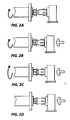
- Figures 2A - 2D are schematic side views of a device depicting steps in inertia welding;
- Figure 3 is a side view depicting a xerographic reproduction machine adapted to incorporate the fuser roll of the present invention;
- Figure 4 is a side view of a fuser core that includes end caps of one material and a support structure of a different material.
- Figure 5 is a an end view of the fuser core of Figure 4;
- Figure 6 is an elevational view of an end cap as shown in Figure 4, and
- Figure 7 is an elevational view of an end cap of a fuser roll of the present invention.
- Referring to Figure 3 of the drawings, there is shown by way of example an automatic
xerographic reproduction machine 10 incorporating a fuser roll structure of the present invention. - The
reproduction machine 10 illustrates the various components utilized in machines of this type for producing copies of a document original 14. -
Reproduction machine 10 has an image-recording photoreceptor 15 in the form of a drum, the outer surface of which is a suitablephotoconductive material 16.Photoreceptor 15 is suitably journaled for rotation within the machine frame (not shown) as by means ofshaft 17. Amain drive motor 19 is drivingly coupled tophotoreceptor 15,motor 19 rotatingphotoreceptor 15 in the direction indicated by arrow 18 to bring thephotoconductive surface 16 ofphotoreceptor 15 past a series of xerographic processing stations. Asuitable controller 21, with microprocessor 22 andmemory 23, is provided for operating in predetermined timed relationship the various components ofmachine 10 to reproduce the document original 14 upon a sheet of final support material, such ascopy sheet 20. As will be understood by those familiar with the art,memory 23 may comprise suitable read-only memory (ROM), random access memory (RAM), and/or non-volatile memory (NVM),memory 23 serving to store the various operating parameters forreproduction machine 10, and the copy run information programmed by the user. - Initially, the
photoconductive surface 16 ofphotoreceptor 15 is uniformly charged by a suitable charging device, such asscorotron 25 at charging station 24. Thecharged surface 16 is selectively exposed atexposure station 26 to create a latent electrostatic image of the document original 14 onphotoreceptor 15. For this purpose, a suitable supporting surface orplaten 28 for document original 14 is provided having a scan aperture or slit 30 therethrough. A suitable document transport, depicted herein as inlet and outlet constant-velocity roll pairs past scan slit 30.Roll pairs main driver motor 19,roll pair 32 being coupled through an electromagnetically operatedclutch 34. A suitable document sensor (not shown) is provided at the inlet toplaten 28 for sensing the insertion of a document original 14 to be copied and initiating operation of thereproduction machine 10. - A
lamp 35, which is disposed belowplaten 28, serves to illuminatescan slit 30 and the line-like portion of the document original 14 thereover. A suitable fiber optictype lens array 37 which may, for example, comprise an array of gradient index fiber elements, is provided to transmit optically the image ray selected from the line-like portion of the document original being scanned to thephotoconductive surface 16 ofphotoreceptor 15 atexposure station 26. - Following exposure, the latent image on the
photoconductive surface 16 ofphotoreceptor 15 is developed at thedevelopment station 40. There, a suitable developer, such as magnetic brush roll 41, which is drivingly coupled tomain drive motor 19, brings a suitable developer mix in developer housing 43 into developing relation with the latent image to develop the image and render the same visible. -
Copy sheets 20 are supported in stack-like fashion on base 44 of copysheet supply tray 45. Suitable biasing means are provided to raise base 44 oftray 45 and bring thetopmost copy sheet 20 in the stack ofsheets 47 into operative relationship with segmented feed rolls 49. Feed rolls 49 are driven bymain motor 19 through an electromagnetically operatedclutch 51 to feed the topmost copy sheet forward into the nip of theregistration roll pair 50 which register the copy sheets with the image on thephotoconductive surface 16 ofphotoreceptor 15.Registration roll pair 50 advance the copy sheet totransfer station 52. There, suitable transfer/detack means, such as transfer/detack corotrons 53, 54, bring the copy sheet into transfer relation with the developed image onphotoconductive surface 16 and separate the copy sheet therefrom for fixing and discharge as a finished copy. - Following
transfer station 52, the image-bearing copy sheet is transported to fuser 100 where the toner images are rendered permanent. - The fused copy is transported by
roll pair 56 to a suitable receptacle such as an output tray (not shown).Registration roll pair 50 andtransport roll pair 56 are driven bymain drive motor 19 through suitable driving means such as belts and pulleys. - Following transfer, residual developer remaining on the
photoconductive surface 16 ofphotoreceptor 15 is removed atcleaning station 62 by means ofcleaning blade 63. Developer removed byblade 63 is deposited into a suitable collector 64 for removal. - While a drum-type photoreceptor is shown and described herein, it will be understood that other photoreceptor types may be employed, such as belt, web, etc.
- To permit effective and controlled charging of the
photoconductive surface 16 byscorotron 25 to a predetermined level necessitates that any residual charges on thephotoconductive surface 16 or trapped in the photoreceptor be removed prior to charging. Anerase device 69 is provided for this purpose. - The
fuser 100 comprises a heat and pressure roll fuser including a heatedfuser roll 101 and apressure roll 110. As illustrated in Figures 4 - 6, thefuser roll core 101 comprises anextruded aluminium tube 120,drive end cap 125 andend cap 130. Theend caps tube 120 by a process described in further detail below. -
Tube 120, in a preferred embodiment, is made of aluminum alloy 6063-T5. It is made by heating an aluminum extrusion ingot, placing the heated ingot in an extrusion press and forcing it through an opening of the desired shape. The aluminum takes on the shape of the steel die, forming a single hollow extrusion. The resulting tube has excellent grain structure, uniform allying element distribution and can be easily welded and machined. End caps 125 and 130 area preferably made from a different alloy. - As seen in Figure 1, heretofore, finely-machined end caps were mated to finely-machined fuser roll cylinders. This method of preparing end caps for mating with fuser rolls is quite costly. In order to reduce the cost of attaching end caps to fuser roll cylinders, inertia welding of the three parts together is. In inertia welding generally, as shown in Figure 2A, one workpiece is fixed in a stationary holding device. The other is clamped in a spindle chuck, usually with an attached flywheel, and is accelerated rapidly. At a predetermined speed, driving power is removed and the fixed workpiece is thrust against the rotating workpiece. Friction between the two workpieces, as shown in Figure 2B, decelerates the flywheel, converting stored energy to frictional heat which is enough to soften, but not melt, faces of the workpieces. With reference to Figure 2C, just before relative rotation ceases, the two workpieces bond together. The remaining flywheel energy hot works the metal interface, expelling any impurities or voids and refining grain structure. In Figure 2D, the weld is complete when the flywheel stops.
- When inertial welding strongly dissimilar materials, the chances for a consistent metallurgical weld, and the cost of the weld, are directly proportional to the amount of joint preparation taken. Figures 4 - 6 disclose a joint design that allows for a locking effect to replace the metallurgical weld as the provider of joint strength.
- Both steel end caps 125 and 130 are inertia welded to cylindrical
aluminum fuser structure 101 in the same manner. For example,end cap 125 is placed into a collet (not shown) and cylindricalfuser support member 101 is held stationary. The collet is spun using a flywheel that is turned by a motor. Gradually thefuser core 101 is moved into contact with the end cap, and the friction between them causes the aluminum tube to melt intorelieved portion 127 of the end cap. Driving of the end cap is stopped just before the support structure is brought into contact with the end cap, but rotation of the end cap continues. Once the driving force to the end cap is removed, melting of the aluminum continues for as short period and then the aluminum solidifies and thereby stops the further movement of the end cap. A conventional heater in the form of a lamp (not shown) is inside the core tube when the fuser roll is in place inside a machine, and it heats the covering on the core tube. The heat from the lamp serves to expand the aluminum further and locks it into the recessed space of the end cap. This method of welding dissimilar metals is so efficient that reclaiming the fuser is made extremely practical once the fuser structure covering is used up. - When inertia welding similar materials, the chances for consistent metallurgical bonds, cost of the welds, and the debris left inside the core are directly proportional to the type of joint preparation used. With known welding techniques used to join end caps and cores of similar metals, the debris left inside the core may break off and hit the heater inside the core and cause hot spots or short the heater out. This necessitates the costly process of going into the machine to remove the fuser and subsequently remove the heater from the fuser roll. This debris could be machined out of the core, but that would be quite costly. A cost-effective method of joining two similar materials is disclosed in Figure 7, and allows for trapping of debris left from the welding process which would normally be left inside the
core 150. Theend cap 156 of Figure 7 has atrap area 158 in the form of a rectangular groove that catches the "rams horns" 157 or excess debris that accumulates oncefuser core 153 andend cap 156 are inertia welded together as heretofore described. The "rams horns" that are created externally of the core is machined off to present a smooth and uniform appearance. - A cost-effective method of attaching end caps to a fuser roll core has been disclosed that includes inertia welding the end caps to the core. Either the core or the end caps can be rotated during the inertia welding. For example, when welding similar metals, a spinning aluminum fuser roll cylinder is moved over the portion of a stationary aluminum end cap that is orthogonal to a vertical wall surface of the middle portion of the end cap and is pushed against the middle portion of the end cap. The aluminum melts by friction and forms "rams horns" that substantially fill a rectangular groove that is part of the orthogonal portion of the end cap. The aluminum also flows to form external "rams horns", but this 'bead' is removed subsequently by machining. This method has the advantage of improved control of debris left inside the hollow roll as compared with allowing pieces of the debris to flail around uncontrollably within the roll.
Claims (5)
1. A fuser roll structure made of similar materials comprising a first drive end cap and a second end cap (156) each secured to the ends of a hollow cylindrical core (153) by inertia (friction) welding, each end cap having in it a recess (158) to contain flash created inside the core by the welding process.
2. The fuser roll structure of claim 1, wherein the end caps and core are made of an aluminum alloy.
3. The fuser roll structure of claim 1, wherein the recess in each end cap is initially rectangular in cross-section.
4. A method of fabricating a fuser roll structure, including the steps of:
(a) providing a hollow cylindrical aluminum tube (153);
(b) providing end caps (156) of a similar material to mate with the ends of the tube (153), each end cap having a cavity (158) formed in its outer surface;
(c) securing the tube;
(d) spinning at least one end cap;
(e) bringing the tube into contact with the spinning end cap, thereby creating friction between the tube and the end cap that causes a portion of the tube to melt into the said cavity, thereby creating an interlock between the tube and the end cap when the molten aluminum solidifies, and
(f) repeating step (e) for the other end cap.
5. The method of claim 5, including the step of machining away any excess flash that extends beyond the outside surface of the tube.
Applications Claiming Priority (2)
| Application Number | Priority Date | Filing Date | Title |
|---|---|---|---|
| US34505189A | 1989-04-28 | 1989-04-28 | |
| US345051 | 1989-04-28 |
Publications (2)
| Publication Number | Publication Date |
|---|---|
| EP0395385A2 true EP0395385A2 (en) | 1990-10-31 |
| EP0395385A3 EP0395385A3 (en) | 1991-07-03 |
Family
ID=23353268
Family Applications (1)
| Application Number | Title | Priority Date | Filing Date |
|---|---|---|---|
| EP19900304462 Withdrawn EP0395385A3 (en) | 1989-04-28 | 1990-04-25 | Fuser rolls |
Country Status (2)
| Country | Link |
|---|---|
| EP (1) | EP0395385A3 (en) |
| JP (1) | JPH02300780A (en) |
Cited By (4)
| Publication number | Priority date | Publication date | Assignee | Title |
|---|---|---|---|---|
| EP0632237A1 (en) * | 1993-05-19 | 1995-01-04 | PHILIPP KREIS GmbH & Co. TRUMA-GERÄTEBAU | Air heater for small spaces |
| EP1248161A3 (en) * | 2001-04-06 | 2004-11-24 | Eastman Kodak Company | Roller structure for operation at elevated temperatures |
| US7988032B2 (en) | 2009-02-25 | 2011-08-02 | Rolls-Royce Plc | Method of welding tubular components |
| CN115673527A (en) * | 2022-11-14 | 2023-02-03 | 中国重汽集团济南动力有限公司 | A new type of friction welding welding device and its welding method |
Family Cites Families (4)
| Publication number | Priority date | Publication date | Assignee | Title |
|---|---|---|---|---|
| US3291466A (en) * | 1964-09-30 | 1966-12-13 | Xerox Corp | Xerographic fixing device |
| US3437032A (en) * | 1965-07-01 | 1969-04-08 | Xerox Corp | Heated fuser roll |
| DE3115790A1 (en) * | 1981-04-18 | 1982-11-04 | Ed. Züblin AG, 7000 Stuttgart | Process for producing truss members |
| FR2544806A1 (en) * | 1983-04-20 | 1984-10-26 | Studer Norbert | Method of assembling two coaxial components of revolution, of the same diameter |
-
1990
- 1990-04-23 JP JP10731890A patent/JPH02300780A/en active Pending
- 1990-04-25 EP EP19900304462 patent/EP0395385A3/en not_active Withdrawn
Cited By (4)
| Publication number | Priority date | Publication date | Assignee | Title |
|---|---|---|---|---|
| EP0632237A1 (en) * | 1993-05-19 | 1995-01-04 | PHILIPP KREIS GmbH & Co. TRUMA-GERÄTEBAU | Air heater for small spaces |
| EP1248161A3 (en) * | 2001-04-06 | 2004-11-24 | Eastman Kodak Company | Roller structure for operation at elevated temperatures |
| US7988032B2 (en) | 2009-02-25 | 2011-08-02 | Rolls-Royce Plc | Method of welding tubular components |
| CN115673527A (en) * | 2022-11-14 | 2023-02-03 | 中国重汽集团济南动力有限公司 | A new type of friction welding welding device and its welding method |
Also Published As
| Publication number | Publication date |
|---|---|
| JPH02300780A (en) | 1990-12-12 |
| EP0395385A3 (en) | 1991-07-03 |
Similar Documents
| Publication | Publication Date | Title |
|---|---|---|
| JPH0627960B2 (en) | Small-mass heat-press fusion device | |
| US4563073A (en) | Low mass heat and pressure fuser and release agent management system therefor | |
| AU694075B2 (en) | Developer cartridge and developing apparatus | |
| US6094559A (en) | Fixing apparatus having cleaning mode and storage medium storing program therefor | |
| US4582416A (en) | Low mass heat and pressure fuser | |
| US5682587A (en) | Developing apparatus using hollow magnet roller | |
| EP0181723A1 (en) | Low mass heat and pressure fuser | |
| JP3391830B2 (en) | Spliced flexible member | |
| US4081213A (en) | Fuser drive system | |
| EP0395385A2 (en) | Fuser rolls | |
| US4653897A (en) | Low mass conformable heat and pressure fuser | |
| JPS62133474A (en) | Heat pressure roll fuser and roll engaging mechanism | |
| GB2053414A (en) | Rollers | |
| CA2217908C (en) | Insert for mounting wires to corotron frames and method of remanufacturing corotrons | |
| JPH02300779A (en) | Fixing roll construction | |
| EP0884655A1 (en) | Method and apparatus for increasing the mechanical strength of liquid developed image on an intermediate transfer member | |
| US5001030A (en) | Method and means for transferring electrostatically charged image powder | |
| US5136338A (en) | Method and apparatus for solid recovery of waste toner | |
| JPH0219882A (en) | Fusing roll structural body comprising three members | |
| JPH05265271A (en) | Color image forming device capable of switching driving speed | |
| EP0464804A2 (en) | Electrophotographic process and apparatus | |
| JPS62121475A (en) | Fixing roll structural body and manufacture thereof | |
| JP2975810B2 (en) | Image forming device | |
| JPH08314269A (en) | Process cartridge, image forming apparatus, and method for molding seal member of developing container | |
| JP2548793B2 (en) | Color image forming method |
Legal Events
| Date | Code | Title | Description |
|---|---|---|---|
| PUAI | Public reference made under article 153(3) epc to a published international application that has entered the european phase |
Free format text: ORIGINAL CODE: 0009012 |
|
| AK | Designated contracting states |
Kind code of ref document: A2 Designated state(s): DE FR GB |
|
| PUAL | Search report despatched |
Free format text: ORIGINAL CODE: 0009013 |
|
| AK | Designated contracting states |
Kind code of ref document: A3 Designated state(s): DE FR GB |
|
| 17P | Request for examination filed |
Effective date: 19911223 |
|
| 17Q | First examination report despatched |
Effective date: 19930426 |
|
| STAA | Information on the status of an ep patent application or granted ep patent |
Free format text: STATUS: THE APPLICATION HAS BEEN WITHDRAWN |
|
| 18W | Application withdrawn |
Withdrawal date: 19931026 |