EP0395188B2 - A device for measuring physical parameters - Google Patents
A device for measuring physical parameters Download PDFInfo
- Publication number
- EP0395188B2 EP0395188B2 EP19900201080 EP90201080A EP0395188B2 EP 0395188 B2 EP0395188 B2 EP 0395188B2 EP 19900201080 EP19900201080 EP 19900201080 EP 90201080 A EP90201080 A EP 90201080A EP 0395188 B2 EP0395188 B2 EP 0395188B2
- Authority
- EP
- European Patent Office
- Prior art keywords
- capacitor
- circuit
- voltage
- measuring
- period
- Prior art date
- Legal status (The legal status is an assumption and is not a legal conclusion. Google has not performed a legal analysis and makes no representation as to the accuracy of the status listed.)
- Expired - Lifetime
Links
Images


Classifications
-
- G—PHYSICS
- G01—MEASURING; TESTING
- G01K—MEASURING TEMPERATURE; MEASURING QUANTITY OF HEAT; THERMALLY-SENSITIVE ELEMENTS NOT OTHERWISE PROVIDED FOR
- G01K1/00—Details of thermometers not specially adapted for particular types of thermometer
- G01K1/02—Means for indicating or recording specially adapted for thermometers
- G01K1/024—Means for indicating or recording specially adapted for thermometers for remote indication
-
- G—PHYSICS
- G01—MEASURING; TESTING
- G01K—MEASURING TEMPERATURE; MEASURING QUANTITY OF HEAT; THERMALLY-SENSITIVE ELEMENTS NOT OTHERWISE PROVIDED FOR
- G01K7/00—Measuring temperature based on the use of electric or magnetic elements directly sensitive to heat ; Power supply therefor, e.g. using thermoelectric elements
- G01K7/16—Measuring temperature based on the use of electric or magnetic elements directly sensitive to heat ; Power supply therefor, e.g. using thermoelectric elements using resistive elements
- G01K7/22—Measuring temperature based on the use of electric or magnetic elements directly sensitive to heat ; Power supply therefor, e.g. using thermoelectric elements using resistive elements the element being a non-linear resistance, e.g. thermistor
- G01K7/24—Measuring temperature based on the use of electric or magnetic elements directly sensitive to heat ; Power supply therefor, e.g. using thermoelectric elements using resistive elements the element being a non-linear resistance, e.g. thermistor in a specially-adapted circuit, e.g. bridge circuit
- G01K7/245—Measuring temperature based on the use of electric or magnetic elements directly sensitive to heat ; Power supply therefor, e.g. using thermoelectric elements using resistive elements the element being a non-linear resistance, e.g. thermistor in a specially-adapted circuit, e.g. bridge circuit in an oscillator circuit
Definitions
- the invention relates to a device for measuring physical parameters, in particular suitable for measuring temperature, comprising a probe including a sensor element capable of converting the value to be measured into an electrical signal.
- Temperatures are measured in known manner, for example, by means of mercury and alcohol thermometers. Furthermore, electronic thermometers are also known.
- the disadvantages of the known thermometers are that the device with which the temperature is measured is directly connected to the appurtenant read-out means, such as a reading scale or dial, a display, and the like.
- the appurtenant read-out means such as a reading scale or dial, a display, and the like.
- a passive probe for wirelessly measuring temperature.
- This known probe comprises a resonant circuit which can be brought into resonance by a high-frequency interrogation field. Coupled to the resonant circuit is an RC oscillator which comprises a temperature-dependent resistor. The temperature-dependent resistor determines the oscillating frequency of the RC oscillator.
- the probe is activated.
- the resonant circuit gets into the resonant state and the RC oscillator begins to oscillate at a frequency depending on the ambient temperature of the temperature-sensitive resistor.
- the signal from the RC oscillator modulates the high-frequency signal induced in the resonant circuit in phase, which is detected in the transmitter/receiver.
- a probe which, in addition to measuring signals can provide binary identification signals to identify the wearer (human being, animal, article, apparatus or any part thereof) of the probe. This latter is of particular importance if a plurality of probes are used, with each probe being fixedly arranged within or at a different wearer or different part of the same wearer.
- Netherlands patent 176404 discloses a passive electronic responder comprising a receiver circuit and a digital circuit, which in operation receives supply energy from a rectifying circuit connected to the receiver circuit.
- the digital circuit further provides, in operation, a binary identification signal which, through a switch element, can modulate the AC voltage induced in the receiver circuit, by periodically attenuating the receiver circuit.
- US-A-4 075 632 relates to a telemetering system comprising a interrogator/generator which generates at least one single rf signal, a transponder for receiving that signal and for amplitude modulating it in accordance with information selected for transmitting it back to the interrogator.
- information can comprise a measuring signal and a digitally coded signal for identifying the transponder whereby said signals are simultaneously superimposed on the rf carrier of the rf signal.
- the known responder does not, however, comprise a sensor element and a digital measuring circuit and accordingly can not be used as a measuring probe.
- Fig. 1 shows diagrammatically an example of a measuring device according to the invention with a transmitter/receiver 1 and a measuring probe 2.
- the transmitter/receiver generates, through a transmitting coil 3, an electromagnetic interrogation field.
- a probe 2 is present in the interrogation field, which probe has a receiving circuit 4 with a coil L, a mutual inductive coupling is established, as indicated by a double arrow M.
- the receiver circuit 4 comprises a resonant circuit LC tuned to the frequency of the interrogation field.
- the receiver circuit can draw energy from the interrogation field in the manner described, for example, in Netherlands patent 176404, which, through a rectifying circuit 5 can be supplied as supply power to an active digital circuit 6 of the passive probe.
- a clock signal generator 9 which in its simplest form may be a one-sided rectifier, but also, for example, a flipflop.
- the digital circuit provides a binary output signal which controls a switch element 7.
- the switch element 7 attenuates and/or detunes the resonant circuit LC in the rhythm of the binary output signal, which can be detected at the transmitter/receiver end.
- a sensor element 8 is connected to digital circuit 6, the electrical value of which depends upon a physical parameter to be measured.
- the choice of the sensor element depends upon the nature of the physical parameter to be measured.
- the sensor element comprises an NTC resistor, so that the probe is suitable for measuring the temperature.
- the temperature or other physical parameter measured is converted by the digital circuit into a binary signal, which can be supplied as a control signal to switch element 7.
- the digital circuit further preferably comprises a pre-determined binary identification code which, before or after the binary measuring signal, is supplied to the switch element 7 as a control signal. If identification is not necessary or not desirable, a code consisting exclusively of noughts or ones can be programmed, so that the signal ultimately generated by the probe and received by the transmitter/receiver only represents the measured value.
- the resistance of an NTC resistor depends according to an exponential function upon the temperature.
- R ref reference resistance
- the measuring range of the thermometer is adjustable throughout a large temperature range.
- the NTC resistance value equals the reference resistance at a temperature x.
- the conversion factor B from temperature to resistance should be accurately fixed. B is a material constant selected during the manufacture of the NTC resistor. If, during the manufacturing process, the absolute value of both the NTC resistance and the reference resistance only has a slight tolerance, the resistors need not be adjusted.
- the electronic circuit of the measuring probe has the task of comparing the NTC resistance and the reference resistance with each other.
- the circuit can function with the available power of about 10 ⁇ W, which is withdrawn from the interrogation field.
- the offset resistance R off is in practice only a calculating magnitude and R off is not present in the actual thermometer.
- an offset voltage is generated and stored in a memory. This voltage has the same value as the voltage across an imaginary offset resistor during the measuring period. Subsequently this voltage is electronically added to the voltage across the NTC resistor. The result ultimately is that the remainder of the circuit responds equally to a real series circuit of NTC and offset resistors.
- Fig. 2 shows diagrammatically in the form of a block diagram the construction of a temperature measuring probe according to the invention. If the probe is present in an interrogation field, the receiver circuit 4 again provides, through a rectifying circuit 5, supply voltage V DD for the active components of the probe. Furthermore, there is again shown a clock signal generator 9, which provides clock signals to code circuit 10, which contains the identification code of the probe.
- a measuring circuit 11 which will be described in more detail hereinafter, is connected to an NTC resistor R ntc for measuring the temperature and with a constant current source I o , which through the measuring circuit 11 is alternately connected to the NTC resistor and to a reference resistor R ref .
- the measuring circuit 11 receives control signals, such as synchronization signals, reset signals, clock signals, and the like, from a control signal generator 12.
- the control signal generator also controls a switch element 14, whose position determines whether the output of code circuit 10 or the output of measuring circuit 11 provides the control signal for the switch element 7.
- Fig. 2 is highly schematical. Parts of different blocks, for example, may actually be combined. On the other hand, in practice, the circuits shown as one block in Fig. 2 may consist of a plurality of scattered parts.
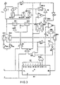
- the temperature measured is shown on the data outputs D o of a binary counter IC 1 , indicated in Fig. 3, in binary form.
- the binary temperature code is subsequently combined in a binary or other suitable code form with a binary identification code in the responder memory.
- the complete code can then be transmitted through field modulation to a processing unit (transmitter/receiver).
- the circuit begins to operate after the reset input R has assumed the logic value "0". Under the control of a clock signal CL, the binary counter (IC 1 ) begins to count from the reset value 0.
- capacitor C1 is each time charged through ES1 and discharged through ES2.
- the charge which thus flows away is Stored in a capacitor C2, across which the voltage increases.
- differential amplifier A2 the voltage across capacitor C2 is copied across a capacitor C3 until counter IC 1 has reached the position 384.
- Q 8 and Q 9 are "1" and ES5 is opened because the output of AND gate N5 becomes "0".
- the voltage across C3 can then no longer change.
- OR gate N4 AND gate N6, inverter N7 and OR gate N10, the circuit is reset. Capacitors C1 and C2 are thereby discharged through switches ES7, ES8 and ES2.
- capacitor C1 is discharged through switches ES2 and ES7, while capacitor C2 is discharged through switches ES7 and ES8.
- Capacitor C3 is simultaneously charged through switch ES5 to the offset voltage V off A2 of amplifier A2.
- capacitor C4 is also charged through switch ES7, amplifier A1, amplifier or inverter A3, switch ES10, and switch ES13 through the section kI o of the constant current source.
- the section (1-k)I o of the current source has been put out of operation by switch ES11 at that moment.
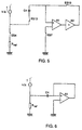
- Fig. 6 shows that capacitor C4, at the end connected to amplifier A1, carries the offset voltage of amplifier A1V offA2 ,and at the other end a voltage -kI o R ref , so that the voltage across C4 is accordingly V offA1 + kI o R ref .
- the value 384 has been selected for p, which corresponds to a counter position in which Q 8 and Q 9 are "1".
- V c3 V offA1 + k.I o R ref .
- V ref is replaced by R ntc .
- V' c2 V c2 + V offA2 .
- V c2 V c3
- the amplifier A2 which is connected as a comparator, reverses, and via switch ES6 stops the counter.
- the counter position now reached depends on the temperature. After deducting the starting value of 512, at temperatures lower than T ref the counter position will be lower than 384, while for temperatures upwards of T ref the counter position will exactly be higher than 384.
- the counter position minus position (512) at the beginning of condition 3 now forms a binary representation of the temperature of the NTC resistor, and, with or without further processing, may be transmitted to the transmitter/receiver similarly to the identification code.
- Fig. 4a shows the position of counter IC 1 which increases by increments of 250 ⁇ s from the starting value 0 to a certain value, which value depends on the temperature.
- the numbers presented in decimals in Fig. 2a are actually binary figures indicated by outputs Q 1 to Q 10 of IC 1 .
- Fig. 4b shows the reset signal provided by external logic.
- the value of the reset signal determines the moment when measurement starts. In this figure, the measurement begins at the transition of reset value 1 to 0.
- Fig. 4c shows the voltage, and the variation therein, across capacitor C1. At R ref , this voltage is temperature-independent. At R ntc , the voltage is a function of the temperature.
- Fig. 4d shows the voltage variation across capacitor C2 as a function of the position of counter IC 1 .
- the slope of the voltage curve in the period associated with counter positions between 0 and 384 is determined by the reference resistance and is hence independent of the temperature.
- the NTC resistor provides curve V c2 between counter position 512 and counter position 832....959.
- the only criterion applying to termination is that voltages V c2 and V c3 should be equal.
- the amplifier A2 operating as a comparator provides a positive output signal, as a result of which AND in Fig. 2f assumes a high level and the counter stops.
- the counter position reached between 832 and 959 is a measure for the temperature measured. When the counter does not stop in the range indicated, the value of the counter indicated is left out of account as a temperature.
- an NTC resistor has been used for determining temperatures.
- the exponential character of this resistor is used in the measuring circuit.
- a transducer is desired for, for example, measuring light intensity, a light-dependent resistor (LDR) may be used.
- LDR light-dependent resistor
- Other non-linear resistors may be used as well. It is then necessary for the measuring circuit to be adapted, without, however, changing the essential features of the apparatus. This is the case, for example, with pressure-dependent resistors or electrolytic solutions which begin to behave as a resistor.
- circuits described can be realized by the low-voltage MOS IC technique.
Landscapes
- Physics & Mathematics (AREA)
- General Physics & Mathematics (AREA)
- Nonlinear Science (AREA)
- Arrangements For Transmission Of Measured Signals (AREA)
Description
For p switching cycles, we have
p. (Rref + k Rref) with
n. (Rntc + k Rref) as a result of which, in spite of an exponential relationship between the resistance value of an NTC resistor and the temperature, there is yet obtained a substantially linear relationship between n (the counter position at the end of the measurement) and T through a sufficiently large temperature range around a reference temperature Tref, with Rntc = Rref.
| Condition | Position IC1 | Electronic Switch Nr. | ||||||||||||
| 1 | 2 | 3 | 4 | 5 | 6 | 7 | 8 | 9 | 10 | 11 | 12 | 13 | ||
| | 0 | 0 | 1 | 0 | 1 | 1 | 0 | 1 | 1 | 0 | 1 | 0 | 0 | 1 |
| 1 | 0 | 1 | 0 | 0 | 1 | 1 | 0 | 0 | 0 | 1 | 0 | 1 | 1 | 0 |
| | 0 | 0 | 1 | 0 | 1 | 1 | 0 | 0 | 0 | 1 | 0 | 1 | 1 | 0 |
| 2 | 1-383 | 1 | 0 | 0 | 1 | 1 | 0 | 0 | 0 | 1 | 0 | 1 | 1 | 0 |
| 2a | 1-383 | 0 | 1 | 0 | 1 | 1 | 0 | 0 | 0 | 1 | 0 | 1 | 1 | 0 |
| 3 | 384-511 | 0 | 1 | 0 | 1 | 0 | 0 | 1 | 1 | 0 | 1 | 0 | 0 | 1 |
| 3a | 384-511 | 0 | 1 | 0 | 1 | 0 | 0 | 1 | 1 | 0 | 1 | 0 | 0 | 1 |
| 4 | 512-... | 1 | 0 | 1 | 0 | 0 | 1 | 0 | 0 | 1 | 0 | 1 | 1 | 0 |
| 4a | 512-... | 0 | 1 | 1 | 0 | 0 | 1 | 0 | 0 | 1 | 0 | 1 | 1 | 0 |
- Condition RESET: Start of each measuring cycle. Capacitors C1, C2 and C3 are discharged. Capacitor C4 is charged to the voltage described before, which is the sum of the offset voltage of amplifier A1 and the voltage across the imaginary offset resistor.
- Condition 1: This is the condition immediately after the reset signal R drops off. The position of
switches ES1 and ES2 is dependent upon the phase of the clock signal, so that, just as at
counter positions 1 to 383, there are alternate switches fromcondition 1 to 1a and from 1a to 1. The same applies toconditions 2 and 2a. - Condition 2: This is the condition at which voltages across C2 and C3 are generated by means of the
voltage generated across Rref and Roff. When the counter position has passed value 383, C3 will retain
the voltage across Rref + the
imaginary R off 384 times. - Condition 3: This is the condition in which a condition resembling the RESET situation is reached with the only difference that the C3 is not discharged. All switches, except ES5, are reset. The counter, however, is not reset. The voltage across C3 will be used during the second part or the measuring cycle (512-...) as a comparative value for the voltage across C2. The voltage across C2 in that period will be obtained as the result of repeated addition of the voltage across Rntc + Roff instead of that across Rref + Roff.
- Condition 4: This is a condition which largely corresponds to
condition 2. Instead of Rref, however, resistor Rntc is connected to the constant current source of value Io. Switch ES5 is still open and switch ES6 is closed, so that in the condition: Vc2 = Vc3 comparator A2 will reverse and further counting will become impossible. In that final situation, depending on the temperature, the counter position will range between 832 and 959.
Claims (6)
- A device for measuring physical parameters, in particular suitable for measuring temperature, comprising a probe (2) including a sensor element (8) capable of converting the value to be measured into an electrical signal and a digital code circuit (6,10), in which an identification code is stored, said probe including a receiving circuit (4) in which an AC voltage can be induced by an electromagnetic field which, in operation, is generated by a transmitter/receiver(1) forming part of the measuring device, which AC voltage can be modulated depending on the measured value of the physical parameter and a digital identification code generated by the digital code circuit, characterised in that the receiving circuit (4) comprises a resonant circuit tuned to the frequency of the electromagnetic field, the probe (2) further comprises a substantially digital measuring circuit (6) connected to the sensor element (8) for generating a binary signal representing the value to be measured and the digital identification code generated by the digital code circuit is a binary identification code, wherein, in operation, the code circuit (6,10) and the measuring circuit (6,11) successively, through a switch element (7), modulate the AC voltage induced in the resonant circuit (4) with the binary signal and the binary identification code respectively.
- A measuring device as claimed in claim 1, in which the sensor element (8) as a resistance value depending on the physical parameter to be measured, characterized in that the digital measuring circuit (6,11) comprises first controllable switches (ES4,ES3) which, in operation, successively connect a predetermined reference resistor (Rref) and the sensor element (8) with a constant current source (lo); that the digital measuring circuit (6,11) has second controllable switches (ES1,ES2) via which a first capacitor (C1), is repeatedly charged a predetermined number of times from the voltage provided over the reference resistor (Rref) in a first period when the reference resistor (Rref) is connected to the current source, which charges are stored in a second capacitor (C2) in order to charge said second capacitor (C2) in a predetermined number of increments corresponding to said predetermined number of times and in a second period, through the first capacitor (C1), in a number of corresponding increments, charge the second capacitor (C2) from the voltage provided by the sensor element (8) when the sensor element (8) is connected to the current source (lo), wherein the second capacitor (C2) is discharged between the first and the second period, and the number of increments needed in the second period for charging the second capacitor (C2) to the same voltage as in the first period is counted by means of a counter (IC1) and provides a measure for the parameter to be measured.
- A measuring device as claimed in claim 2, characterized in that the digital measuring circuit (6,11) comprises a binary counter (IC1) to which, in operation, clock pulses (CL) are supplied continuously, and whose outputs (Q8-Q10) control the controllable switches, while also at least a number of outputs (PO) of the binary counter indicate the number of increments of the second period.
- A measuring device as claimed in claim 2 or 3, characterized by a third capacitor (C3) which during the first period is connected to the second capacitor (C2) and takes over the charge from said second capacitor (C2), and which by means of a controllable switch (ES5) is uncoupled from said second capacitor (C2) at the end of the first period.
- A measuring device as claimed in claim 4, characterized in that the second and third capacitors (C2,C3) are each connected during the second period to an input of a comparator (A2), the output of which is connected to the counter (IC1), said comparator providing an output signal as soon as the voltage at the second capacitor (C2) equals the voltage at the third capacitor (C3) which output signal causes the binary counter (IC1) to stop.
- A measuring device as claimed in any of claims 2-5, adapted to measure temperatures by means of an NTC resistor (Rntc), characterized by a fourth capacitor (C4) which before the beginning of the first and between the first and the second period is connected to a part (klo) of the constant current source (lo) through controllable switches (ES12,ES13), the voltage generated across the fourth capacitor (C4) increasing the measuring accuracy and linearising the NTC resistor (Rntc).
Applications Claiming Priority (2)
| Application Number | Priority Date | Filing Date | Title |
|---|---|---|---|
| NL8901079 | 1989-04-28 | ||
| NL8901079A NL8901079A (en) | 1989-04-28 | 1989-04-28 | PASSIVE ELECTRONIC RECORDER. |
Publications (3)
| Publication Number | Publication Date |
|---|---|
| EP0395188A1 EP0395188A1 (en) | 1990-10-31 |
| EP0395188B1 EP0395188B1 (en) | 1994-04-06 |
| EP0395188B2 true EP0395188B2 (en) | 1998-09-30 |
Family
ID=19854573
Family Applications (1)
| Application Number | Title | Priority Date | Filing Date |
|---|---|---|---|
| EP19900201080 Expired - Lifetime EP0395188B2 (en) | 1989-04-28 | 1990-04-27 | A device for measuring physical parameters |
Country Status (3)
| Country | Link |
|---|---|
| EP (1) | EP0395188B2 (en) |
| DE (1) | DE69007842T3 (en) |
| NL (1) | NL8901079A (en) |
Families Citing this family (11)
| Publication number | Priority date | Publication date | Assignee | Title |
|---|---|---|---|---|
| EP0608250B1 (en) * | 1991-09-13 | 1996-05-15 | Rodney Arthur Stafford | Electronic animal identification system |
| NL9201072A (en) * | 1992-06-18 | 1994-01-17 | Nedap Nv | INTEGRATED MICROWAVE / INDUCTIVE TRANSPONDER. |
| US5466614A (en) * | 1993-09-20 | 1995-11-14 | At&T Global Information Solutions Company | Structure and method for remotely measuring process data |
| FR2717261B1 (en) * | 1994-03-09 | 1996-07-26 | Datamax Electronique Sarl | Probe device and its use in particular for measuring the temperature in an enclosed space and in an environment hostile to humans. |
| DE4434240C1 (en) * | 1994-09-24 | 1995-11-30 | Norbert H L Dr Ing Koster | Dynamic modulation arrangement for transponder with compact structure |
| NL1000369C2 (en) * | 1995-05-16 | 1996-11-19 | Idento Electronics Bv | Measuring device for wireless temperature measurement. |
| NL1000844C2 (en) * | 1995-07-19 | 1997-01-21 | Wavin Repox B V | Remote detection system for temperature changes without wired transducers |
| DE19540527A1 (en) * | 1995-10-31 | 1997-05-07 | Hewlett Packard Gmbh | Identification modules for exchangeable components in analytical instruments |
| US5691635A (en) * | 1996-01-29 | 1997-11-25 | Fluke Corporation | Probe identification system for a measurement instrument |
| US5984875A (en) * | 1997-08-22 | 1999-11-16 | Innotek Pet Products, Inc. | Ingestible animal temperature sensor |
| DE102010063613B4 (en) * | 2010-06-24 | 2012-09-27 | Ust Umweltsensortechnik Gmbh | Passive remote-sensing temperature sensor |
Family Cites Families (3)
| Publication number | Priority date | Publication date | Assignee | Title |
|---|---|---|---|---|
| US3978471A (en) * | 1975-03-26 | 1976-08-31 | Weston Instruments, Inc. | Digital thermometer using a dual slope a/d converter without a high precision voltage source |
| GB1577920A (en) * | 1976-11-01 | 1980-10-29 | Nedap Nv | Detection plate for identification systems |
| US4150573A (en) * | 1976-12-03 | 1979-04-24 | Tokyo Shibaura Electric Co., Ltd. | Electronic digital thermometer |
-
1989
- 1989-04-28 NL NL8901079A patent/NL8901079A/en not_active Application Discontinuation
-
1990
- 1990-04-27 EP EP19900201080 patent/EP0395188B2/en not_active Expired - Lifetime
- 1990-04-27 DE DE1990607842 patent/DE69007842T3/en not_active Expired - Fee Related
Also Published As
| Publication number | Publication date |
|---|---|
| DE69007842T3 (en) | 1999-05-20 |
| EP0395188A1 (en) | 1990-10-31 |
| NL8901079A (en) | 1990-11-16 |
| DE69007842T2 (en) | 1994-09-22 |
| EP0395188B1 (en) | 1994-04-06 |
| DE69007842D1 (en) | 1994-05-11 |
Similar Documents
| Publication | Publication Date | Title |
|---|---|---|
| EP0395188B1 (en) | A device for measuring physical parameters | |
| EP0313575B1 (en) | Transmitter with vernier measurement | |
| US3453546A (en) | Telemeter adaptable for implanting in an animal | |
| US4371271A (en) | Electronic thermometer | |
| US4531526A (en) | Remote sensor telemetering system | |
| IL113607A (en) | Method of making quartz crystals | |
| WO2001092830A1 (en) | Sensor device, setting device, reading device, and article administration system | |
| US8018323B2 (en) | RFID sensor device based on pulse-processing | |
| US5007042A (en) | Method and apparatus for transmitting analog data embedded in a digital pulse train | |
| EP0726451A1 (en) | Electronic thermometer with audible temperature rise indicator | |
| US3704414A (en) | Frequency meter | |
| TW200521418A (en) | Radio frequency temperature sensor and temperature cablibrating method therefor | |
| US3940752A (en) | Transducing system | |
| US4370070A (en) | Digital thermometer having Fahrenheit and Celsius readout modes | |
| Kaiser | Passive telemetric readout system | |
| US4838707A (en) | Electronic Thermometer | |
| US3475742A (en) | Temperature telemetering system | |
| US3978729A (en) | Circuit for monitoring temperature of high-voltage equipment | |
| CA1189166A (en) | Remote sensor telemetering system and method | |
| JPH01502449A (en) | measurement circuit | |
| NL9001877A (en) | TEMPERATURE MEASUREMENT SYSTEM. | |
| WO1987000951A1 (en) | Inductance systems | |
| US4100542A (en) | Measuring system | |
| EP1872143B1 (en) | Method and device for measuring resistance | |
| WO1986001595A1 (en) | Improvements in or relating to thermometers |
Legal Events
| Date | Code | Title | Description |
|---|---|---|---|
| PUAI | Public reference made under article 153(3) epc to a published international application that has entered the european phase |
Free format text: ORIGINAL CODE: 0009012 |
|
| AK | Designated contracting states |
Kind code of ref document: A1 Designated state(s): DE FR GB NL |
|
| 17P | Request for examination filed |
Effective date: 19910326 |
|
| 17Q | First examination report despatched |
Effective date: 19920914 |
|
| GRAA | (expected) grant |
Free format text: ORIGINAL CODE: 0009210 |
|
| AK | Designated contracting states |
Kind code of ref document: B1 Designated state(s): DE FR GB NL |
|
| REF | Corresponds to: |
Ref document number: 69007842 Country of ref document: DE Date of ref document: 19940511 |
|
| ET | Fr: translation filed | ||
| PLBI | Opposition filed |
Free format text: ORIGINAL CODE: 0009260 |
|
| 26 | Opposition filed |
Opponent name: GESELLSCHAFT FUER MOBIL- UND SATELLITENFUNKTECHNIK Effective date: 19941223 |
|
| NLR1 | Nl: opposition has been filed with the epo |
Opponent name: GESELLSCHAFT FUR MOBIL- UND SATELLITENFUNKTECHNIK |
|
| PLAW | Interlocutory decision in opposition |
Free format text: ORIGINAL CODE: EPIDOS IDOP |
|
| PLAW | Interlocutory decision in opposition |
Free format text: ORIGINAL CODE: EPIDOS IDOP |
|
| PUAH | Patent maintained in amended form |
Free format text: ORIGINAL CODE: 0009272 |
|
| STAA | Information on the status of an ep patent application or granted ep patent |
Free format text: STATUS: PATENT MAINTAINED AS AMENDED |
|
| 27A | Patent maintained in amended form |
Effective date: 19980930 |
|
| AK | Designated contracting states |
Kind code of ref document: B2 Designated state(s): DE FR GB NL |
|
| NLR2 | Nl: decision of opposition | ||
| ET3 | Fr: translation filed ** decision concerning opposition | ||
| NLR3 | Nl: receipt of modified translations in the netherlands language after an opposition procedure | ||
| REG | Reference to a national code |
Ref country code: GB Ref legal event code: IF02 |
|
| PGFP | Annual fee paid to national office [announced via postgrant information from national office to epo] |
Ref country code: GB Payment date: 20060426 Year of fee payment: 17 |
|
| PGFP | Annual fee paid to national office [announced via postgrant information from national office to epo] |
Ref country code: DE Payment date: 20060629 Year of fee payment: 17 |
|
| PGFP | Annual fee paid to national office [announced via postgrant information from national office to epo] |
Ref country code: NL Payment date: 20070417 Year of fee payment: 18 |
|
| GBPC | Gb: european patent ceased through non-payment of renewal fee |
Effective date: 20070427 |
|
| NLV4 | Nl: lapsed or anulled due to non-payment of the annual fee |
Effective date: 20071101 |
|
| PG25 | Lapsed in a contracting state [announced via postgrant information from national office to epo] |
Ref country code: NL Free format text: LAPSE BECAUSE OF NON-PAYMENT OF DUE FEES Effective date: 20071101 Ref country code: DE Free format text: LAPSE BECAUSE OF NON-PAYMENT OF DUE FEES Effective date: 20071101 |
|
| PG25 | Lapsed in a contracting state [announced via postgrant information from national office to epo] |
Ref country code: GB Free format text: LAPSE BECAUSE OF NON-PAYMENT OF DUE FEES Effective date: 20070427 |
|
| PGFP | Annual fee paid to national office [announced via postgrant information from national office to epo] |
Ref country code: FR Payment date: 20070405 Year of fee payment: 18 |
|
| REG | Reference to a national code |
Ref country code: FR Ref legal event code: ST Effective date: 20081231 |
|
| PG25 | Lapsed in a contracting state [announced via postgrant information from national office to epo] |
Ref country code: FR Free format text: LAPSE BECAUSE OF NON-PAYMENT OF DUE FEES Effective date: 20080430 |