EP0394972A2 - Infusion pump with associated rotary encoder - Google Patents
Infusion pump with associated rotary encoder Download PDFInfo
- Publication number
- EP0394972A2 EP0394972A2 EP90107784A EP90107784A EP0394972A2 EP 0394972 A2 EP0394972 A2 EP 0394972A2 EP 90107784 A EP90107784 A EP 90107784A EP 90107784 A EP90107784 A EP 90107784A EP 0394972 A2 EP0394972 A2 EP 0394972A2
- Authority
- EP
- European Patent Office
- Prior art keywords
- primary
- photo
- rotary plate
- slits
- rotary encoder
- Prior art date
- Legal status (The legal status is an assumption and is not a legal conclusion. Google has not performed a legal analysis and makes no representation as to the accuracy of the status listed.)
- Granted
Links
Images

Classifications
-
- G—PHYSICS
- G01—MEASURING; TESTING
- G01D—MEASURING NOT SPECIALLY ADAPTED FOR A SPECIFIC VARIABLE; ARRANGEMENTS FOR MEASURING TWO OR MORE VARIABLES NOT COVERED IN A SINGLE OTHER SUBCLASS; TARIFF METERING APPARATUS; MEASURING OR TESTING NOT OTHERWISE PROVIDED FOR
- G01D5/00—Mechanical means for transferring the output of a sensing member; Means for converting the output of a sensing member to another variable where the form or nature of the sensing member does not constrain the means for converting; Transducers not specially adapted for a specific variable
- G01D5/26—Mechanical means for transferring the output of a sensing member; Means for converting the output of a sensing member to another variable where the form or nature of the sensing member does not constrain the means for converting; Transducers not specially adapted for a specific variable characterised by optical transfer means, i.e. using infrared, visible, or ultraviolet light
- G01D5/32—Mechanical means for transferring the output of a sensing member; Means for converting the output of a sensing member to another variable where the form or nature of the sensing member does not constrain the means for converting; Transducers not specially adapted for a specific variable characterised by optical transfer means, i.e. using infrared, visible, or ultraviolet light with attenuation or whole or partial obturation of beams of light
- G01D5/34—Mechanical means for transferring the output of a sensing member; Means for converting the output of a sensing member to another variable where the form or nature of the sensing member does not constrain the means for converting; Transducers not specially adapted for a specific variable characterised by optical transfer means, i.e. using infrared, visible, or ultraviolet light with attenuation or whole or partial obturation of beams of light the beams of light being detected by photocells
- G01D5/36—Forming the light into pulses
Definitions
- the present invention relates to a rotary encoder.
- a rotary encoder comprises a rotary plate having a plurality of slits defined therein and spaced an equal distance from each other in a direction circumferentially thereof. These slits are selectively sensed by a sensor during rotation of the rotary plate to determine the angle of rotation of the rotary plate in terms of the number of slits detected and also to determine the peripheral velocity of the rotary plate in terms of the number of slits detected for a given length of time.
- the detection of the peripheral velocity of the rotary plate is essentially such as to detect the angle of rotation from a position at which rotation of the rotary plate is initiated.
- the prior art rotary encoder is unable to detect the angle of rotation of the rotary plate from a specific reference angular position during the continued rotation of the rotary plate.
- the present invention has been devised with a view to substantially eliminate the above discussed incapability inherent in the prior art rotary encoder and has for its essential object to provide an improved rotary encoder capable of detecting the angle of rotation of the rotary plate from the specific reference angular position.
- a rotary encoder which comprises a rotary plate having a plurality of primary slits defined in the rotary plate in a circular row coaxial with the axis of rotation of the rotary plate, said rotary plate also having at least one reference slit defined therein at a position radially of the circular row of the primary slits, a primary photoelectric detector including a source of light and a photo-sensor positioned one above the other with the circular row of the primary slits intervening therebetween, and an auxiliary photoelectric detector including a source of light and a photo-sensor positioned one above the other with the path of travel of the reference slit intervening therebetween.
- the primary slits in the rotary plate can be successively detected by the first photoelectric detector whereas the passage of the reference slit can be detected by the auxiliary photoelectric detector.
- reference numeral 1 represents a rotary disc and reference numerals 2 and 3 represent primary and auxiliary photoelectric detectors, respectively.
- the rotary disc 1 and the first and second photoelectric detectors 2 and 3 altogether constitute a rotary encoder 4, which is used in a parenteral solution infusion pump.
- the rotary disc 1 has its outer peripheral portion formed with a plurality of primary slits 5 defined therein in a circular row and in circumferentially equally spaced relationship with each other and also with at least one reference slit 6 defined at a position radially inwardly of the circular row of the primary slits 5.
- the primary photoelectric detector 2 comprises a source of light 7 and a photo-sensor 8 and is disposed with the light source 7 and the photo-sensor 8 positioned above and beneath the circular row of the primary slits 5, respectively.
- the auxiliary photoelectric detector 3 comprises a source of light 9 and a photo-sensor 10 and is disposed with the light source 9 and the photo-sensor 10 positioned above and beneath the path of travel of the reference slit 6, respectively.
- Both of the first and second photoelectric detectors 2 and 3 are mounted on and fixedly supported by a generally U- shaped housing 12 having upper and lower arms 12a and 12b connected together by means of a transverse body.
- a drive shaft 13 coupled at one end with a drive motor (not shown) and at the opposite end with the rotary disc 1 extends rotatably, but axially non-movably through the upper and lower arms 12a and 12b of the U-shaped housing 12.
- a stack of eccentric cam plates 15 is mounted on a portion of the drive shaft 13 situated between the upper and lower arms 12a and 12b of the housing for rotation together with the drive shaft 13, each of said eccentric cam plates 15 being integrated with a respective finger 16 which extends radially outwardly therefrom.
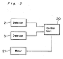
- a signal emerging from the primary photo-detector 2, which is indicative of the number of the primary slits 5 having traversed the path of light from the light source 7 towards the photo-sensor 8, and a signal emerging from the auxiliary photo-detector 3, which is indicative of the passage of the reference slit 6 across the path of light from the light source 9 towards the photo-sensor 10, are supplied to a control unit 20.
- the control unit 20 is so designed as to execute a predetermined control program in response to the application of the respective signals from the primary and auxiliary photo-detectors 2 and 3 thereto thereby to apply a drive signal to the motor (not shown) coupled with the drive shaft 13.
- Reference numeral 30 shown in Fig. 1 represents a parenteral solution infusion piping having an upstream end fluid-coupled with an infusion bottle or bag and a downstream end fluid-coupled with a needle or catheter, a substantially intermediate portion of said infusion piping being held in position contactable with the fingers 16.
- the substantially intermediate portion of the infusion piping is so positioned relative to the fingers 16 that, during the rotation of the drive shaft 13 in one direction with the fingers 16 consequently successively driven outwards to press the substantially intermediate portion of the infusion piping in the order from the uppermost or upstream one of the fingers 16 down to the lowermost or downstream one of the fingers 16, an infusion liquid within the infusion piping can be successively conveyed from an upstream side down to a downstream side in a pulsating fashion.
- the infusion pump shown in Fig. 1 is of a construction effective to cause that portion of the solution infusion piping 30 to undergo a linear peristaltic motion to transport the infusion liquid successively towards the needle or catheter and then into a vascular system, for example, a vein, of a patient.
- infusion pump of a type employing similar fingers adapted to be successively driven by associated cam members is well known to those skilled in the art and is disclosed in, for example, the Japanese Laid-open Utility Model Publication No. 60-163938, published October 31, 1985, reference to which is herein incorporated.
- the infusion pump of the above described construction has a problem associated with the transportation of the infusion liquid through the infusion piping 30. Since the infusion liquid is transported in a pulsating fashion through that portion of the infusion piping 30, the amount of parenteral solution infusion liquid transported per stroke of each of the fingers 16 varies from the upstream side to the downstream side with respect to the direction of flow thereof towards the needle or catheter, with the minimum amount attained at the lowermost finger 16.
- the control unit 20 shown in Fig. 3 is so designed and so constructed as to execute the following sequence. Namely, the timing at which the uppermost finger 16 is driven to press the infusion piping 30 is controlled so as to match with the timing at which the auxiliary photo-detector 3 provides an output signal indicative of the passage of the reference slit 6 therethrough during the rotation of the rotary disc 1, while the number of output signals emerging from the primary photo-detector 2 and indicative of the number of the primary slits 5 detected thereby subsequent to the detection of the passage of the reference slit 6 past the auxiliary photo-detector 3 is counted.
- the time during which the amount of the parenteral solution infusion liquid transported by the lowermost finger 16 is reduced can be advantageously shortened, thereby relieving a pulsating phenomenon of flow of the infusion liquid.
- the primary slits are successively detected by the primary photo-detector comprised of the light source and the photo-sensor while the reference slit is detected by the auxiliary photo-detector similarly comprised of the light source and the photo-detector. Therefore, with the utilization of the output signal from the auxiliary photo-detector indicating the passage of the reference slit as a reference, it is possible to detect the angle of rotation at any position on the path of rotation of the rotary plate.
Landscapes
- Physics & Mathematics (AREA)
- General Physics & Mathematics (AREA)
- Infusion, Injection, And Reservoir Apparatuses (AREA)
- Optical Transform (AREA)
Abstract
Description
- The present invention relates to a rotary encoder.
- According to the prior art, a rotary encoder comprises a rotary plate having a plurality of slits defined therein and spaced an equal distance from each other in a direction circumferentially thereof. These slits are selectively sensed by a sensor during rotation of the rotary plate to determine the angle of rotation of the rotary plate in terms of the number of slits detected and also to determine the peripheral velocity of the rotary plate in terms of the number of slits detected for a given length of time.
- With the prior art rotary encoder, however, the detection of the peripheral velocity of the rotary plate is essentially such as to detect the angle of rotation from a position at which rotation of the rotary plate is initiated. The prior art rotary encoder is unable to detect the angle of rotation of the rotary plate from a specific reference angular position during the continued rotation of the rotary plate.
- Accordingly, the present invention has been devised with a view to substantially eliminate the above discussed incapability inherent in the prior art rotary encoder and has for its essential object to provide an improved rotary encoder capable of detecting the angle of rotation of the rotary plate from the specific reference angular position.
- In order to accomplish this and other objects of the present invention, there is provided, in accordance with the present invention, a rotary encoder which comprises a rotary plate having a plurality of primary slits defined in the rotary plate in a circular row coaxial with the axis of rotation of the rotary plate, said rotary plate also having at least one reference slit defined therein at a position radially of the circular row of the primary slits, a primary photoelectric detector including a source of light and a photo-sensor positioned one above the other with the circular row of the primary slits intervening therebetween, and an auxiliary photoelectric detector including a source of light and a photo-sensor positioned one above the other with the path of travel of the reference slit intervening therebetween.
- According to the present invention, during the rotation of the rotary plate, the primary slits in the rotary plate can be successively detected by the first photoelectric detector whereas the passage of the reference slit can be detected by the auxiliary photoelectric detector.
- This and other objects and features of the present invention will become clear from the following description taken in conjunction with a preferred embodiment thereof with reference to the accompanying drawings, in which:
- Fig. 1 is a schematic side sectional view of an infusion pump;
- Fig. 2 is a schematic top plan view of a rotary encoder used in the infusion pump according to a preferred embodiment of the present invention; and
- Fig. 3 is a block circuit diagram showing a control system coupled with the rotary encoder.
- Referring to the drawings, particularly to Figs. 1 and 2,
reference numeral 1 represents a rotary disc andreference numerals rotary disc 1 and the first and secondphotoelectric detectors - The
rotary disc 1 has its outer peripheral portion formed with a plurality ofprimary slits 5 defined therein in a circular row and in circumferentially equally spaced relationship with each other and also with at least onereference slit 6 defined at a position radially inwardly of the circular row of theprimary slits 5. The primaryphotoelectric detector 2 comprises a source of light 7 and a photo-sensor 8 and is disposed with the light source 7 and the photo-sensor 8 positioned above and beneath the circular row of theprimary slits 5, respectively. Similarly, the auxiliaryphotoelectric detector 3 comprises a source of light 9 and a photo-sensor 10 and is disposed with the light source 9 and the photo-sensor 10 positioned above and beneath the path of travel of thereference slit 6, respectively. - Both of the first and second
photoelectric detectors shaped housing 12 having upper andlower arms drive shaft 13 coupled at one end with a drive motor (not shown) and at the opposite end with therotary disc 1 extends rotatably, but axially non-movably through the upper andlower arms housing 12. A stack ofeccentric cam plates 15 is mounted on a portion of thedrive shaft 13 situated between the upper andlower arms drive shaft 13, each of saideccentric cam plates 15 being integrated with arespective finger 16 which extends radially outwardly therefrom. - Referring now to Fig. 3 showing a block circuit diagram of a control system for the rotary encoder 4, a signal emerging from the primary photo-
detector 2, which is indicative of the number of theprimary slits 5 having traversed the path of light from the light source 7 towards the photo-sensor 8, and a signal emerging from the auxiliary photo-detector 3, which is indicative of the passage of thereference slit 6 across the path of light from the light source 9 towards the photo-sensor 10, are supplied to acontrol unit 20. Thecontrol unit 20 is so designed as to execute a predetermined control program in response to the application of the respective signals from the primary and auxiliary photo-detectors drive shaft 13. - Hereinafter, the operation of the system shown in and described with reference to Figs. 1 and 2 will be described.
-
Reference numeral 30 shown in Fig. 1 represents a parenteral solution infusion piping having an upstream end fluid-coupled with an infusion bottle or bag and a downstream end fluid-coupled with a needle or catheter, a substantially intermediate portion of said infusion piping being held in position contactable with thefingers 16. More specifically, the substantially intermediate portion of the infusion piping is so positioned relative to thefingers 16 that, during the rotation of thedrive shaft 13 in one direction with thefingers 16 consequently successively driven outwards to press the substantially intermediate portion of the infusion piping in the order from the uppermost or upstream one of thefingers 16 down to the lowermost or downstream one of thefingers 16, an infusion liquid within the infusion piping can be successively conveyed from an upstream side down to a downstream side in a pulsating fashion. In other words, the infusion pump shown in Fig. 1 is of a construction effective to cause that portion of thesolution infusion piping 30 to undergo a linear peristaltic motion to transport the infusion liquid successively towards the needle or catheter and then into a vascular system, for example, a vein, of a patient. - The infusion pump of a type employing similar fingers adapted to be successively driven by associated cam members is well known to those skilled in the art and is disclosed in, for example, the Japanese Laid-open Utility Model Publication No. 60-163938, published October 31, 1985, reference to which is herein incorporated.
- The infusion pump of the above described construction has a problem associated with the transportation of the infusion liquid through the
infusion piping 30. Since the infusion liquid is transported in a pulsating fashion through that portion of theinfusion piping 30, the amount of parenteral solution infusion liquid transported per stroke of each of thefingers 16 varies from the upstream side to the downstream side with respect to the direction of flow thereof towards the needle or catheter, with the minimum amount attained at thelowermost finger 16. - In view of the foregoing, the
control unit 20 shown in Fig. 3 is so designed and so constructed as to execute the following sequence. Namely, the timing at which theuppermost finger 16 is driven to press theinfusion piping 30 is controlled so as to match with the timing at which the auxiliary photo-detector 3 provides an output signal indicative of the passage of thereference slit 6 therethrough during the rotation of therotary disc 1, while the number of output signals emerging from the primary photo-detector 2 and indicative of the number of theprimary slits 5 detected thereby subsequent to the detection of the passage of thereference slit 6 past the auxiliary photo-detector 3 is counted. When theprimary slits 5 having passed through the primary photo-detector 2 in a number corresponding to the angle of rotation of therotary disc 1 during a period from the timing at which theuppermost finger 16 presses theinfusion piping 30 until the timing at which one of thefingers 16 which is spaced two fingers from thelowermost finger 16, that is, thethird finger 16 counted backwards from thelowermost finger 16, presses theinfusion piping 30, are detected, a command necessary to increase the number of revolutions of thedrive motor 21 is supplied to themotor 21 to accelerate a pressing action accomplished successively by the lowermost threefingers 16. - By the foregoing control performed in the practice of the present invention, the time during which the amount of the parenteral solution infusion liquid transported by the
lowermost finger 16 is reduced can be advantageously shortened, thereby relieving a pulsating phenomenon of flow of the infusion liquid. - Thus, according to the present invention, the primary slits are successively detected by the primary photo-detector comprised of the light source and the photo-sensor while the reference slit is detected by the auxiliary photo-detector similarly comprised of the light source and the photo-detector. Therefore, with the utilization of the output signal from the auxiliary photo-detector indicating the passage of the reference slit as a reference, it is possible to detect the angle of rotation at any position on the path of rotation of the rotary plate.
- Although the present invention has been fully described in connection with the preferred embodiment thereof with reference to the accompanying drawings, it is to be noted that various changes and modifications are apparent to those skilled in the art. By way of example, although the primary and auxiliary photo-detectors have been shown and described as used separate from each other, the both may be integrated together. When both detectors are integrated, a single light source may be employed for both of tee primary and auxiliary photo-detectors.
- Such changes and modifications are to be understood as included within the scope of the present invention as defined by the appended claims unless they depart therefrom.
Claims (2)
a rotary plate having a plurality of primary slits defined therein in a circular row coaxial with an axis of rotation of the rotary plate, said rotary plate also having at least one reference slit defined therein at a position radially of the circular row of the primary slits;
a primary photoelectric detector including a source of light and a photo-sensor positioned one above the other with the circular row of the primary slits intervening therebetween; and
an auxiliary photoelectric detector including a source of light and a photo-sensor positioned one above the other with the path of travel of the reference slit intervening therebetween.
Applications Claiming Priority (3)
| Application Number | Priority Date | Filing Date | Title |
|---|---|---|---|
| JP1111230A JPH02290509A (en) | 1989-04-28 | 1989-04-28 | Rotary encoder |
| JP111230/89 | 1989-04-28 | ||
| CA002015557A CA2015557C (en) | 1989-04-28 | 1990-04-26 | Rotary encoder |
Publications (3)
| Publication Number | Publication Date |
|---|---|
| EP0394972A2 true EP0394972A2 (en) | 1990-10-31 |
| EP0394972A3 EP0394972A3 (en) | 1991-02-27 |
| EP0394972B1 EP0394972B1 (en) | 1993-08-11 |
Family
ID=25674101
Family Applications (1)
| Application Number | Title | Priority Date | Filing Date |
|---|---|---|---|
| EP90107784A Expired - Lifetime EP0394972B1 (en) | 1989-04-28 | 1990-04-24 | Infusion pump with associated rotary encoder |
Country Status (4)
| Country | Link |
|---|---|
| EP (1) | EP0394972B1 (en) |
| JP (1) | JPH02290509A (en) |
| CA (1) | CA2015557C (en) |
| DE (1) | DE69002674T2 (en) |
Cited By (2)
| Publication number | Priority date | Publication date | Assignee | Title |
|---|---|---|---|---|
| WO2019068990A1 (en) | 2017-10-03 | 2019-04-11 | Faiveley Transport Tours | Contact strip of a pantograph for a rail vehicle, method for manufacturing and method for monitoring such a strip, system for monitoring the wear of such a strip and rail vehicle |
| WO2019158846A1 (en) | 2018-02-15 | 2019-08-22 | Faiveley Transport Tours | Contact strip of a pantograph, and corresponding rail vehicle and monitoring method |
Family Cites Families (5)
| Publication number | Priority date | Publication date | Assignee | Title |
|---|---|---|---|---|
| US4266125A (en) * | 1978-12-21 | 1981-05-05 | Hewlett-Packard Company | Optical shaft angle encoder |
| US4236880A (en) * | 1979-03-09 | 1980-12-02 | Archibald Development Labs, Inc. | Nonpulsating IV pump and disposable pump chamber |
| EP0066636A1 (en) * | 1981-06-05 | 1982-12-15 | Siemens Aktiengesellschaft | Optical pulse generator, especially an angular position transducer |
| DE3247313A1 (en) * | 1982-12-21 | 1984-06-28 | Ivac Corp., San Diego, Calif. | Method and device for regulating a fluid flow |
| US4869646A (en) * | 1984-10-15 | 1989-09-26 | American Hospital Supply Corp. | Continuous peristaltic pump |
-
1989
- 1989-04-28 JP JP1111230A patent/JPH02290509A/en active Pending
-
1990
- 1990-04-24 DE DE90107784T patent/DE69002674T2/en not_active Expired - Lifetime
- 1990-04-24 EP EP90107784A patent/EP0394972B1/en not_active Expired - Lifetime
- 1990-04-26 CA CA002015557A patent/CA2015557C/en not_active Expired - Lifetime
Cited By (2)
| Publication number | Priority date | Publication date | Assignee | Title |
|---|---|---|---|---|
| WO2019068990A1 (en) | 2017-10-03 | 2019-04-11 | Faiveley Transport Tours | Contact strip of a pantograph for a rail vehicle, method for manufacturing and method for monitoring such a strip, system for monitoring the wear of such a strip and rail vehicle |
| WO2019158846A1 (en) | 2018-02-15 | 2019-08-22 | Faiveley Transport Tours | Contact strip of a pantograph, and corresponding rail vehicle and monitoring method |
Also Published As
| Publication number | Publication date |
|---|---|
| EP0394972B1 (en) | 1993-08-11 |
| JPH02290509A (en) | 1990-11-30 |
| EP0394972A3 (en) | 1991-02-27 |
| DE69002674T2 (en) | 1994-03-17 |
| CA2015557C (en) | 1995-01-24 |
| DE69002674D1 (en) | 1993-09-16 |
Similar Documents
| Publication | Publication Date | Title |
|---|---|---|
| US5279556A (en) | Peristaltic pump with rotary encoder | |
| EP0266716B1 (en) | A transfusion apparatus | |
| US5531680A (en) | Enteral feeding pump motor unit and method of use | |
| CA2199161C (en) | System for determining motor position in a biomedical device | |
| US4965446A (en) | Optical interrupter system with vibration compensation | |
| EP0215249A1 (en) | A transfusion apparatus | |
| AU706031B2 (en) | Sheet feeding apparatus and method | |
| EP0530773A1 (en) | Bubble detection method for infusion pump apparatus | |
| JPS6445982A (en) | Low pulsation feed fluid pump | |
| EP0871847B1 (en) | Infusion pump monitoring encoder/decoder | |
| JPS56113083A (en) | Choke detection method and device for peristaltic liquid pump | |
| CN106226543B (en) | Rack for test tube position induction device and check meter | |
| JPS5774631A (en) | Detector for load torque | |
| EP0462238B1 (en) | Device for monitoring the rotation of a drive shaft, for instance in a peristaltic pump | |
| CA2015557C (en) | Rotary encoder | |
| EP0417869B1 (en) | Collation error indication system for collator | |
| CN2374843Y (en) | Automatic detecting device for thickness of paper money | |
| KR890004902Y1 (en) | Infusion apparatus | |
| JPS6450909A (en) | Detecting device of abnormality of encoder | |
| JPH0418062Y2 (en) | ||
| JPH0330115Y2 (en) | ||
| JPS5629496A (en) | Detecting system for operational malfunction of pulse motor | |
| JPS6321418Y2 (en) | ||
| JPS62218355A (en) | Paper sheet stacking device | |
| JPS6456976A (en) | Fixed pressure control device for fluid feed pump |
Legal Events
| Date | Code | Title | Description |
|---|---|---|---|
| PUAI | Public reference made under article 153(3) epc to a published international application that has entered the european phase |
Free format text: ORIGINAL CODE: 0009012 |
|
| AK | Designated contracting states |
Kind code of ref document: A2 Designated state(s): DE FR GB |
|
| PUAL | Search report despatched |
Free format text: ORIGINAL CODE: 0009013 |
|
| 17P | Request for examination filed |
Effective date: 19901219 |
|
| AK | Designated contracting states |
Kind code of ref document: A3 Designated state(s): DE FR GB |
|
| RHK1 | Main classification (correction) |
Ipc: G01D 5/34 |
|
| 17Q | First examination report despatched |
Effective date: 19920304 |
|
| GRAA | (expected) grant |
Free format text: ORIGINAL CODE: 0009210 |
|
| AK | Designated contracting states |
Kind code of ref document: B1 Designated state(s): DE FR GB |
|
| REF | Corresponds to: |
Ref document number: 69002674 Country of ref document: DE Date of ref document: 19930916 |
|
| ET | Fr: translation filed | ||
| PLBE | No opposition filed within time limit |
Free format text: ORIGINAL CODE: 0009261 |
|
| STAA | Information on the status of an ep patent application or granted ep patent |
Free format text: STATUS: NO OPPOSITION FILED WITHIN TIME LIMIT |
|
| 26N | No opposition filed | ||
| REG | Reference to a national code |
Ref country code: GB Ref legal event code: IF02 |
|
| PGFP | Annual fee paid to national office [announced via postgrant information from national office to epo] |
Ref country code: FR Payment date: 20090331 Year of fee payment: 20 Ref country code: DE Payment date: 20090428 Year of fee payment: 20 |
|
| PGFP | Annual fee paid to national office [announced via postgrant information from national office to epo] |
Ref country code: GB Payment date: 20090422 Year of fee payment: 20 |
|
| REG | Reference to a national code |
Ref country code: GB Ref legal event code: PE20 Expiry date: 20100423 |
|
| PG25 | Lapsed in a contracting state [announced via postgrant information from national office to epo] |
Ref country code: GB Free format text: LAPSE BECAUSE OF EXPIRATION OF PROTECTION Effective date: 20100423 |
|
| PG25 | Lapsed in a contracting state [announced via postgrant information from national office to epo] |
Ref country code: DE Free format text: LAPSE BECAUSE OF EXPIRATION OF PROTECTION Effective date: 20100424 |