EP0394945A2 - System for removal of asbestos material - Google Patents
System for removal of asbestos material Download PDFInfo
- Publication number
- EP0394945A2 EP0394945A2 EP90107716A EP90107716A EP0394945A2 EP 0394945 A2 EP0394945 A2 EP 0394945A2 EP 90107716 A EP90107716 A EP 90107716A EP 90107716 A EP90107716 A EP 90107716A EP 0394945 A2 EP0394945 A2 EP 0394945A2
- Authority
- EP
- European Patent Office
- Prior art keywords
- vacuum
- hopper
- collector
- collection
- valve
- Prior art date
- Legal status (The legal status is an assumption and is not a legal conclusion. Google has not performed a legal analysis and makes no representation as to the accuracy of the status listed.)
- Withdrawn
Links
Images


Classifications
-
- B—PERFORMING OPERATIONS; TRANSPORTING
- B65—CONVEYING; PACKING; STORING; HANDLING THIN OR FILAMENTARY MATERIAL
- B65G—TRANSPORT OR STORAGE DEVICES, e.g. CONVEYORS FOR LOADING OR TIPPING, SHOP CONVEYOR SYSTEMS OR PNEUMATIC TUBE CONVEYORS
- B65G53/00—Conveying materials in bulk through troughs, pipes or tubes by floating the materials or by flow of gas, liquid or foam
- B65G53/34—Details
- B65G53/60—Devices for separating the materials from propellant gas
Definitions
- a short arm 89 To the shaft 85 is fixedly mounted one end of a short arm 89.
- the second end of the arm 89 is rotatably fastened to one corner of a triangular link 91.
- a second corner of the triangular link 91 is pivotally connected to a toggling overcenter link 95 which is pivotally connected to a block 93 on the housing top plate 21.
- the third corner of the triangular link 91 is pivotally connected to one end of a rod 97.
- the second end of the rod 97 is pivotally connected to a lever 99 that extends rigidly from a sleeve 96 about the vertical axis of a spindle 98.
- a handle 101 is fastened to sleeve 96.
Landscapes
- Engineering & Computer Science (AREA)
- Mechanical Engineering (AREA)
- Processing Of Solid Wastes (AREA)
- Working Measures On Existing Buildindgs (AREA)
Abstract
A system for removal of asbestos material comprises a pair of collection and discharge units (3,5). Each unit includes a housing (7), a hopper (9) mounted to the housing (7), and a slide gate valve (5) or valves for selectively sealing and opening the associated hopper (9). A vacuum line (115) and a collector tube (119) are connected to each hopper (9). Suitable valves are installed in the vacuum lines (115) and collector tubes (119). By controlling the slide gate valves (51) and the vacuum line (115) and collector tube valves (133,135), a vacuum can be created in the hoppers (9) alternately to draw material into a selected hopper (9). With the vacuum dissipated from a hopper (9), the sliding gate valve (51) is operable to discharge material from that hopper (9) while the other hopper (9) is being filled, thereby enabling material to be continuously removed from the source (120).
Description
- This invention pertains to environmental protection, and more particularly to the collection and disposal of hazardous and toxic substances.
- It is now well known that building materials containing asbestos can have a harmful effect on the health of the building occupants. For that reason, much time, expense, and effort are being expended to remove asbestos materials from buildings.
- Exemplary apparatus for removing and collecting asbestos materials from buildings is described in my co-pending U.S. patent application Serial Number 199,028, the specification of which is incorporated by reference herein. Briefly, the apparatus of U.S. patent application Serial Number 199,028 comprises a vacuum system for collecting asbestos bearing material into a hopper. A slide gate valve within a housing is manually between opened and closed positions to permit and block, respectively, discharge of the material from the hopper through a spout and into an asbestos bag. An overcenter lock assures sealing contact with the mouth of the hopper when the valve gate is in the closed position. With the valve gate closed and an asbestos bag in place, the housing is completely isolated from the atmosphere so that no asbestos particles can escape.
- The asbestos collection apparatus of U.S. patent application Serial Number 199,028 works very well. Nevertheless, it is considered desirable to more efficiently discharge the collected materials from the hopper into the bags. Specifically, with the prior collection apparatus the vacuum collection of the material into the hopper must be stopped each time the hopper becomes full and the slide gate valve is opened to discharge collected material into a bag. Only after the bag is filled and the valve gate is closed and sealed can the vacuum system be restarted. The intermittent operation of the vacuum collection system results in unproductive time in the actual removal of material from the source.
- Thus, a need exists for improved apparatus for collecting and discharging asbestos material.
- In accordance with the present invention, a system for the removal of asbestos material is provided that enables the material to be continuously collected from a source. This is accomplished by apparatus that includes one or more hoppers together with means for controlling material collection into and discharge from the hoppers.
- Each hopper is mounted to the top of an enclosed housing. Each housing has a discharge spout directly below the hopper. A manually operated slide gate valve within each housing is selectively operable between an opened position wherein the material collected in the associated hopper falls by gravity through the spout into a waiting bag, and a closed position wherein the material remains sealed in the hopper.
- To provide continuous collection of the asbestos material from the source, a common collector tube is branched to connect to both hoppers. Suitable shut off valves are installed in each of the collector tube branches. In a similar manner, a common vacuum line leading from a vacuum pump is branched to both hoppers. Each branch of the vacuum line has a shut off valve.
- In operation, the branch collector tube valve and the branch vacuum line valve associated with one of the hoppers are controlled open, and the branch collector tube and branch vacuum line valves associated with the other hopper are closed. Asbestos material from the source is collected into the hopper connected to the open valves. When that hopper is full, the valves in the branch collector tube and vacuum line associated with the filled hopper are closed, and the valves associated with the other hopper are opened. Asbestos material then flows into the second hopper. While the second hopper is being filled, the slide gate valve of the first hopper is operated to discharge the material collected therein into a bag. After installing a new bag, the valves can be switched again, so that the first hopper is filling while the second hopper is being emptied. In that manner, asbestos material can be continuously removed from the source, with the material being collected in and simultaneously discharged from alternate hoppers.
- Other objects and advantages of the invention will become apparent to those skilled in the art upon reading the description of an illustrative embodiment of the invention which is presented hereafter in reference to the drawings.
-
- Fig. 1 is a perspective view of the system for removing asbestos material.
- Fig. 2 is a front view of the system for removing asbestos material.
- Fig. 3 is a cross sectional view taken along
lines 3--3 of Fig. 1. - Fig. 4 is an enlarged cross sectional view taken along lines 4--4 of Fig. 2.
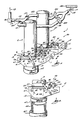
- Fig. 5 is an elevational view of the linkage for raising and lowering a sliding gate valve which is in the fragmentarily shown housing, said linkage being isolated and enlarged relative to Fig. 1 from which the linkage is taken, the linkage being operated to a condition which results in the gate valve being in its unlatched or lowermost portion as also shown in Fig. 4.
- Fig. 6 is similar to Fig. 5 except that the linkage has been operated to a condition which results in the gate valve being in its uppermost or latched condition as is the case in Figs. 2 and 3.
- Fig. 7 is a plan view of the linkage shown in Fig. 6
- Although the disclosure hereof is detailed and exact to enable those skilled in the art to practice the invention, the physical embodiments herein disclosed merely exemplify the invention which may be embodied in other specific structure. The scope of the invention is defined in the claims appended hereto.
- Referring to Fig. 1, a material collection and discharge system 1 is illustrated that includes the present invention. The collection and discharge system 1 is particularly useful for removing asbestos contaminated
material 118 from arepresentative source 120, but it will be understood that the invention is not limited to use with hazardous materials. - The asbestos removal system 1 comprises two generally similar collection and
discharge units 3 and 5 which are preferably fixed to a suitable structural frame, not illustrated. The collection and discharge units and structural frame may be mounted on a truck or similar vehicle, not shown in Fig. 1, for convenient transportation between job sites. Mounting of the collection and discharge units and frame to the truck may be by hydraulically operated beams and other supports that raise and lower the units into working and inoperative positions, respectively. Such beams and supports and their hydraulic controls are not illustrated in the drawings, as those components are well known to persons skilled in the relevant arts and form no part of the present invention. - Typical collection and
discharge unit 3 comprises an enclosedhousing 7, to the top of which is mounted a storage hopper 9. The hopper 9 is depicted as being generally cylindrical in shape with a partially conical lower end 11. However, the hopper may be formed in a variety of other shapes to suit the requirements of the particular user. To the underside of thehousing 7 is fixed adischarge spout 13. - The other collection and discharge unit 5 comprises a hopper 15, a
housing 17, and a spout that are substantially similar to the corresponding components of theunit 3. The other components of the two collection and discharge units are also generally identical to each other. Accordingly, a description of the components of one of the units will be adequate. - As shown in Fig. 3, each hopper, such as hopper 9, is fabricated as an enclosed air-tight thin walled vessel. The lower end 11 of the hopper forms the hopper discharge mouth 19. The hopper is mounted to a
top plate 21 of thehousing 7 by aflange 25. Thehopper flange 25 is sealed to thehousing plate 21 in an air-tight manner byfasteners 23. Joined to theflange 25 is atube 27 that passes through an opening in the housing top plate. The lower end of thetube 27 has an outwardly extendingannular flange 29. In the bottom face of theflange 29 is installed an annular combination seal 31. The combination seal 31 is preferably composed of an O-ring 33 and a wiper 35. - In addition to the
top plate 21, thehousing 7 comprises opposedend walls 37 and 39, afront wall 41, aback wall 42, and a sloped bottom wall 43. Thebottom spout 13 is preferably a short circular tube, and it may be integrally joined to the lower ends of thehousing walls spout 13 and the hopper mouth 19, the housing is fully enclosed. - The
spout 13 has a diameter slightly less than the diameter of aconventional asbestos bag 45. Surrounding the spout and retained thereon is abag clamp 47. Theclamp 47 is shown in the clamped position in Fig. 3. The bag clamp includes a compressible ring 48. When the clamp is actuated, the compressible ring 48 extends below and overlaps thespout end face 52, thereby assuring a positive seal between the spout and the bag. Consequently, when the inside of thebag 45 is washed down (as will be explained hereinafter), no material will remain in the upper portion of the bag. Thus, when the bag is removed from the spout it will be free of contaminants in the closure portion thereof. - To control the flow of
material 49 collected in the hopper 9, a slide gate valve 51 is installed in thehousing 7. The slide gate valve 51 comprises aflat valve gate 53 that is horizontally translatable within the housing in the directions ofarrow 55. To translate thevalve gate 53, it is formed with a series of openings 57 extending vertically therein. Also see Fig. 4. The openings 57 are designed to mesh With the teeth of acog 59 that is mounted on shaft 61 for rotation about a horizontal axis. The shaft 61 is mounted for rotation inbearings 62 in the housing opposed front andback walls tube 27. Rotating the shaft 61 counterclockwise with respect to Fig. 3 causes the gate to translate to the right to the position indicated by the phantom lines 53′, thereby uncovering the hopper mouth. - To rotate the shaft 61 and
cog 59 for translating thevalve gate 53, the shaft 61 extends through thehousing front wall 41. The shaft 61 terminates on the outside of thehousing 7 in ahandle 60. Also see Fig. 2. Thus, by turning thehandle 60 on the outside of the housing, the valve gate is translated inside the housing. - To support the
valve gate 53 within thehousing 7, the slide gate valve 51 further comprises a series of rollers. The rollers are mounted in the housing front andback walls rollers 63 are used in the vicinity of thehopper tube 27, and at least twoadditional sets 65 are employed remote from thetube 27 and close to the housing end wall 39. Therollers 63 are mounted oneccentric shafts 67 that pivotally extend through the housing front and back walls. With theshafts 67 in the position shown in Fig. 4, theroller center lines 69 are at locations below the associated shaft center lines 71. In that condition, thevalve gate 53 is in an unlatched position, resting on therollers 63 such that there is a clearance "C" between the seal 31 and theupper surface 73 of the gate. By rotating theshafts 67 by a mechanism to be described presently, therollers 63 are moved upwardly with respect to Figs. 3 and 4. In turn, the rollers raise the gate a short distance in the direction of arrow 75. Raising the gate places it in a latched position, wherein the clearance "C" is taken up, and the gateupper surface 73 is forced against the seal 31, as shown in Fig. 3. Only when the gate is in the lowered or unlatched position of Fig. 4, away from the seal 31, is thehandle 60 rotated to turn thecog 59 and translate the gate in the directions ofarrow 55. - The
rollers 65 are mounted onstub shafts 77 that are fixed to the housing front andback walls shafts 77 androllers 65 coincide, and those center lines are in line with thecenter lines 69 of therollers 63 when therollers 63 are in the lowered position of Fig. 4. Thus, with therollers 63 in the lowered position, theunlatched valve gate 53 slides easily over therollers cog 59. - To rotate the
eccentric shaft 67 for latching and unlatching thevalve gate 53 of each collection anddischarge unit 3 and 5,respective control linkages 76 are employed. The control linkages are shown in Figs. 1 and 2 and are shown enlarged in Figs. 5-7. Thecontrol linkages 76 of the two collection and discharge units may be mirror images of each other, Fig. 1. Each control linkage includesshort levers 78 that are fixed at one end to the ends ofrespective shafts 67, which protrude outside thehousing walls respective levers 78 are pivotally connected to acommon tie rod 80. One end of thetie rod 80 is connected to anotherlever 81 that is pivotable by means ofshaft 85 in abearing block 87. To theshaft 85 is fixedly mounted one end of ashort arm 89. The second end of thearm 89 is rotatably fastened to one corner of atriangular link 91. A second corner of thetriangular link 91 is pivotally connected to a toggling overcenter link 95 which is pivotally connected to ablock 93 on thehousing top plate 21. The third corner of thetriangular link 91 is pivotally connected to one end of arod 97. The second end of therod 97 is pivotally connected to alever 99 that extends rigidly from a sleeve 96 about the vertical axis of aspindle 98. Ahandle 101 is fastened to sleeve 96. By pushing thehandle 101 of thelever 99 forwardly toward the hoppers 9 and 15, theshort levers 78 of the respective control linkages are rotated to lower therollers 63 and unlatch the valve gate from the hopper tube seal 31. Such a condition is shown in Figs. 1, 4 and 5. Pushinghandle 101 backwardly away from the associated hopper operates thelevers 78 to latch the corresponding valve gate in a sealed position against the hopper seal 31. The latched condition is shown in Figs. 2, 3 and 6. Thearm 89,triangular link 91, and link 95 form an overcenter lock such that the valve gate is positively latched in place when thecorresponding handle 101 is in the back position. This results from the way the link 95 toggles overcenter in Fig. 6 as compared with Fig. 5. - The
housings walls Front nozzles 103 are directed onto thewall 37, and nozzles 105 are located near the end wall 39.Multiple nozzles 107 are mounted to the underside of thevalve gate 53. The various nozzles are arranged to wash the asbestos dust and particles from virtually the entire interior surfaces of the housings and into thebags 45 for the asbestos. - To control operation of the new asbestos collection system 1 various devices may be used that actuate in response to the performance of other components. For example, a
first limit switch 109 may be mounted to eachhousing wall 37 for sensing when the associatedvalve gate 53 is in the closed position under the hopper mouth 19. Actuation of thelimit switch 109 by the closed gate is necessary to start operation of a vacuum system for collectingmaterial 118, fed from themain source 120 in the respective hoppers 9 or 15 where the asbestos material is marked 49 in Fig. 3. Another limit switch 111 can be used to sense the opened valve gate and start operation of a mechanical loading device, not shown, that forces theasbestos material 49 through the hopper mouth 19 andtube 27 and into abag 45. - It is a feature of the present invention that the
asbestos material 118 is drawn on a continuous basis from thesource 120 and is collected alternately into hoppers 9 and 15. With particular attention to Fig. 1,arrow 113 represents the flow of air from the hoppers as evacuated therefrom by avacuum line 115. Thevacuum line 115 is connected to a heavy duty vacuum pump 116. Arrow 117 represents the flow ofasbestos material 118 from atypical source 120 into the hoppers through acollector tube 119 as drawn by the vacuum pump 116. - To control vacuum creation in the hoppers 9 and 15, the
vacuum line 115 has two branches leading therefrom, with vacuum line branch 121 leading to hopper 9 andbranch 123 leading to hopper 15. Installed in the vacuum branch line 121 is a vacuum shut offvalve 125. A similar vacuum shut off valve 127 is installed in thebranch line 123. To direct the flow ofasbestos material 118 alternately into the hoppers 9 and 15, thecollector tube 119 is formed with twobranches Collector branch 129 leads to hopper 9, andcollector branch 131 leads to hopper 15. A shut offvalve 133 is installed incollector branch tube 129. A second shut offvalve 135 is installed in thecollector branch tube 131. - In operation, the asbestos removal system 1 is transported to a location as close as possible to the
asbestos source 120. The hydraulic system on the vehicle, not shown, on which the asbestos removal system is mounted is operated to place the collection anddischarge units 3 and 5 in an operative position relative to the ground. Normally, when in the operative position 55-gallon drums 137 as in Fig. 2 can be placed on the ground under thespouts 13 for holding theasbestos bags 45 for the asbestos material. The bag clamps 47 are opened. The mouth of a bag is placed over the discharge spout of eachcollection unit 3 and 5, and the bag clamps are closed. - For safety purposes, the asbestos collection system controls are designed such that both slide gate valves 51 of the
collection unit 3 or 5 must be cycled at the start of the asbestos removal operation. For that purpose, thehandle 101 of eachcontrol linkage 76 is pushed forwardly toward the respective hoppers 9 and 15 to unlock the overcenter locks that includearms 89 andlinks 91 and 95. Thevalve gates 53 are thus opened. Turning thehandles 60 translate therespective valve gates 53 to uncover the hopper mouths 19 and actuate the rear control limit switches 111. Each valve gate handle 60 is then turned to translate the respective valve gates under the hopper mouths. Pushing the control linkage handles 101 backwardly away from the hoppers causes the valve gates to close and seal against the respective tube seals 31, so that a vacuum can be created in the hoppers to drawasbestos material 118 into them. Closing the valve gates actuates thelimit switches 109, which also form a part of the controls for the hopper vacuum system. - After the slide gate valves 51 of both
collection units 3 and 5 have been cycled and bothvalve gates 53 are closed, the vacuum pump 116 is energized. Although the system 1 may be operated such thatmaterial 118 is collected into both hoppers 9 and 15 serially, it is preferred that the material be collected into one hopper, while it is being discharged from the other. It will be assumed that hopper 9 is to be filled first. Accordingly,vacuum valve 125 is controlled open, and vacuum valve 127 is controlled closed. Consequently, a vacuum is produced in hopper 9. Thevalve 133 incollector tube branch 129 is opened, withvalve 135 incollector branch 131 being closed. As a result,material 118 is drawn throughcollector tube 119 andcollector branch tube 129 in the direction of arrow 117 into the hopper 9. - When the hopper 9 has a sufficient quantity of
asbestos material 49 collected in it, the asbestos removal system controls are actuated to closevacuum valve 125 andcollector valve 133, and to open vacuum valve 127 andcollector valve 135.Material 118 then flows from thesource 120 to the hopper 15. While the hopper 15 is being filled, hopper 9 can be emptied. To empty a hopper, the associatedhandle 101 is pushed forwardly toward the hopper to unlock the overcenter lock of thecontrol linkage 76 and unlatch thegate valve 53. The gate valve handle 60 is turned to slide the valve gate from under the hopper mouth 19 and to actuate the limit switch 111. An optional mechanical unloading device inside the hopper, not illustrated, is energized to assist discharge ofmaterial 49 into the waitingbag 45 below. When the bag is full or the hopper is empty, the valve gate handle 60 is rotated to slide the valve gate under the hopper mouth 19. Thehandle 101 is pushed to latch and seal the valve gate against the tube seal 31. Then suitable control valves are opened to furnish water to thespray nozzles housings 5 and 7. Water is sprayed until only clear water is washed down to theasbestos bag 45 The bag is necked down under thespout 13 and tightly tied. Thebag clamp 47 is unclamped, the filled bag is removed, and a new bag is installed. In that manner, the slide gate valve 51 and the rest of the housing interior are isolated from the hopper interior and from the atmosphere until material is again to be collected into and discharged from the corresponding hopper. - While the hopper 9 of the collection and
discharge unit 3 is being emptied,material 118 is continuously being carried from thesource 120 and is filling the hopper 15 of the collection and discharge unit 5. As soon as the hopper 9 has been emptied, thematerial 49 in the hopper 15 can be emptied. For that purpose, thevacuum valve 125 andcollector valve 133 are reopened. Vacuum valve 127 andcollector valve 135 are closed. Thehandles asbestos material 118 at thesite 120 can be continuously removed and collected into alternate hoppers without interruptions due to hopper emptying. - Thus, it is apparent that there has been provided, in accordance with the invention, a system for removal of asbestos material that fully satisfies the aims and advantages set forth above. While the invention has been described in conjunction with specific embodiments thereof, it is evident that many alternatives, modifications, and variations will be apparent to those skilled in the art in light of the foregoing description. Accordingly, it is intended to embrace all such alternatives, modifications, and variations as fall within the spirit and broad scope of the appended claims.
Claims (13)
1. A system for removal of asbestos material comprising:
a. at least two collection and discharge units, each collection and discharge unit comprising:
i. a generally enclosed housing;
ii. hopper means mounted to the housing for collecting the material; and
iii. gate valve means located in the housing for controlling the discharge of the material collected in the hopper means;
b. collector means connected to the hopper means of each collection and discharge unit for carrying asbestos material from a source thereof to the hopper means of each collection and discharge unit;
c. vacuum means connected to the hopper means of each collection and discharge unit for drawing the asbestos material from the source thereof into the hopper means; and
d. valve means for enabling asbestos material to flow into the hopper means of a selected collection and discharge unit and for blocking material flow into the hopper means of the other collection and discharge unit,
so that asbestos material can be continuously carried from the source thereof and collected in the hopper means of alternate collection and discharge units by selective actuation of the valve means.
2. The system of claim 1 wherein the collector means comprises:
a. a collector tube for carrying asbestos material from the source thereof; and
b. a respective collector branch tube leading from the collector tube to the hopper means of each collection and discharge unit.
3. The system of claim wherein the vacuum means comprises:
a. a vacuum pump;
b. a vacuum line leading to the vacuum pump; and
c. a respective vacuum branch line leading from the vacuum line to the hopper means of each collection and discharge unit.
4. The system of claim 1 wherein the valve means comprises:
a. vacuum valve means installed in the vacuum means for controlling the vacuum produced by the vacuum means in at least a selected one of the hopper means of the collection and discharge units; and
b. collector valve means installed in the collector means for controlling the flow of asbestos material from the source thereof to the hopper means of at least a selected one of the collection and discharge units in response to the vacuum produced therein by the vacuum means and the vacuum valve means.
5. The system of claim 1 wherein:
a. the collector means comprises a collector tube for carrying asbestos material from the source thereof, and a respective branch tube joining the collector tube to the hopper means of each collection and discharge unit;
b. the vacuum means comprises a vacuum line connected to a vacuum source, and a respective branch line joining the vacuum line to the hopper means of each collection and discharge; and
c. the valve means comprises a shut off valve in each of the collector tube branch tubes and in each of the vacuum line branch lines, the shut off valves in the branch collector tubes cooperating with the shut off valves in the branch vacuum lines to alternately enable and block flow of asbestos material to the hopper means of a selected collection and discharge unit.
6. Apparatus for collecting and discharging material comprising:
a. first and second hopper means for collecting material therein;
b. vacuum means for creating a vacuum in a selected one of the hopper means; and
c. collector means for carrying material from a source thereof to a selected one of the hopper means in response to the creation of a vacuum therein by the vacuum means,
so that a vacuum can be created and material collected in alternate hopper means.
7. The apparatus of claim 6 further comprising first and second gate means for selectively cooperating with the respective hopper means to seal the hopper means and permit the creation of a vacuum therein and for unsealing the hopper means to enable the material collected therein to be discharged therefrom,
so that the hopper means can be alternately filled and emptied of material
so that the hopper means can be alternately filled and emptied of material
8. The apparatus of claim 6 wherein the vacuum means comprises:
a. a vacuum pump;
b. first and second vacuum lines connecting the respective hopper means to the vacuum pump; and
c. vacuum valve means installed in the first and second vacuum lines for controlling the vacuum created in the respective hopper means,
so that a vacuum can be created alternately in the first and second hopper means.
9. The apparatus of claim 6 wherein the collector means comprises:
a. first and second collector tubes connected to the respective hopper means; and
b. collector valve means installed in the first and second collector tubes for selectively enabling and blocking carrying of material from the source thereof to a selected one of the hopper means in response to the creation of a vacuum therein by the vacuum means.
10. The apparatus of claim 6 wherein the vacuum means comprises:
a. a vacuum pump;
b. a vacuum line connected to the vacuum pump;
c. first and second vacuum branch lines connecting the vacuum line to the respective first and second hopper means; and
d. first and second vacuum valve means installed in the respective vacuum branch lines for creating a vacuum in a selected hopper means.
11. The apparatus of claim 10 wherein the collector means comprises:
a. a collector tube for carrying material from a source thereof;
b. first and second collector branch tubes connecting the respective first and second hopper means to the collector tube; and
c. first and second collector valve means installed in the respective collector branch tubes for selectively enabling and blocking material flow from the source thereof to the respective hopper means in response to the creation of a vacuum in the selected hopper means,
so that the first and second vacuum valve means and the first and second collector valve means cooperate to carry material to alternate hopper means.
12. A method for removing asbestos material comprising:
a. providing first and second hoppers;
b. creating a vacuum in the first hopper;
c. drawing asbestos material from a source thereof to the first hopper by means of the vacuum created therein;
d. dissipating the vacuum in the first hopper and simultaneously creating a vacuum in the second hopper; and
e. drawing asbestos material from the source thereof into the second hopper and simultaneously discharging asbestos material from the first hopper.
13. The method of claim 12 comprising the further steps of:
a. dissipating the vacuum in the second hopper and simultaneously creating a vacuum in the first hopper; and
b. drawing asbestos material from the source thereof into the first hopper and simultaneously discharging asbestos material from the second hopper,
so that asbestos material is alternately collected into and discharged from the first and second hoppers.
Applications Claiming Priority (2)
| Application Number | Priority Date | Filing Date | Title |
|---|---|---|---|
| US34316089A | 1989-04-25 | 1989-04-25 | |
| US343160 | 1989-04-25 |
Publications (2)
| Publication Number | Publication Date |
|---|---|
| EP0394945A2 true EP0394945A2 (en) | 1990-10-31 |
| EP0394945A3 EP0394945A3 (en) | 1992-06-17 |
Family
ID=23344952
Family Applications (1)
| Application Number | Title | Priority Date | Filing Date |
|---|---|---|---|
| EP19900107716 Withdrawn EP0394945A3 (en) | 1989-04-25 | 1990-04-24 | System for removal of asbestos material |
Country Status (3)
| Country | Link |
|---|---|
| EP (1) | EP0394945A3 (en) |
| JP (1) | JPH038979A (en) |
| CA (1) | CA2015234A1 (en) |
Cited By (2)
| Publication number | Priority date | Publication date | Assignee | Title |
|---|---|---|---|---|
| WO2001087746A1 (en) * | 2000-05-18 | 2001-11-22 | Kabushiki Kaisha Yms | Method and device for pneumatic transportation of powder |
| EP2889239A4 (en) * | 2012-08-27 | 2016-04-27 | Twin Technology Company Ooo | Method for the vacuum-pneumatic transporting of bulk materials with a high mass concentration |
Families Citing this family (1)
| Publication number | Priority date | Publication date | Assignee | Title |
|---|---|---|---|---|
| CN109577607B (en) * | 2018-12-24 | 2023-10-27 | 庄金标 | Algae well |
Citations (5)
| Publication number | Priority date | Publication date | Assignee | Title |
|---|---|---|---|---|
| GB928506A (en) * | 1962-01-03 | 1963-06-12 | Vokes Ltd | Improvements in pneumatic conveyers for tobacco |
| DE3323162A1 (en) * | 1983-06-28 | 1985-01-03 | Motan Gmbh, 7972 Isny | Conveying device |
| EP0130747A2 (en) * | 1983-06-22 | 1985-01-09 | U.K. Asbestos Plant & Machinery Limited | Removal of airborne contaminant |
| JPH0191825A (en) * | 1987-10-05 | 1989-04-11 | Yajo:Kk | Cleaning method for surface of building |
| US4897121A (en) * | 1987-10-05 | 1990-01-30 | Torao Sasaki | Removal process of asbestos-filled linings or coatings |
-
1990
- 1990-04-24 CA CA 2015234 patent/CA2015234A1/en not_active Abandoned
- 1990-04-24 EP EP19900107716 patent/EP0394945A3/en not_active Withdrawn
- 1990-04-25 JP JP10995790A patent/JPH038979A/en active Pending
Patent Citations (5)
| Publication number | Priority date | Publication date | Assignee | Title |
|---|---|---|---|---|
| GB928506A (en) * | 1962-01-03 | 1963-06-12 | Vokes Ltd | Improvements in pneumatic conveyers for tobacco |
| EP0130747A2 (en) * | 1983-06-22 | 1985-01-09 | U.K. Asbestos Plant & Machinery Limited | Removal of airborne contaminant |
| DE3323162A1 (en) * | 1983-06-28 | 1985-01-03 | Motan Gmbh, 7972 Isny | Conveying device |
| JPH0191825A (en) * | 1987-10-05 | 1989-04-11 | Yajo:Kk | Cleaning method for surface of building |
| US4897121A (en) * | 1987-10-05 | 1990-01-30 | Torao Sasaki | Removal process of asbestos-filled linings or coatings |
Cited By (2)
| Publication number | Priority date | Publication date | Assignee | Title |
|---|---|---|---|---|
| WO2001087746A1 (en) * | 2000-05-18 | 2001-11-22 | Kabushiki Kaisha Yms | Method and device for pneumatic transportation of powder |
| EP2889239A4 (en) * | 2012-08-27 | 2016-04-27 | Twin Technology Company Ooo | Method for the vacuum-pneumatic transporting of bulk materials with a high mass concentration |
Also Published As
| Publication number | Publication date |
|---|---|
| EP0394945A3 (en) | 1992-06-17 |
| CA2015234A1 (en) | 1990-10-25 |
| JPH038979A (en) | 1991-01-16 |
Similar Documents
| Publication | Publication Date | Title |
|---|---|---|
| US5685978A (en) | Reclaiming the constituent components of separating and uncured concrete | |
| CA2267582C (en) | On-site concrete truck wash-out apparatus | |
| US4155586A (en) | Tailgate locking system | |
| US4121915A (en) | Vacuum cleaning apparatus | |
| US5095959A (en) | Slide gate valve system for asbestos collection apparatus | |
| EP0394945A2 (en) | System for removal of asbestos material | |
| US5487228A (en) | Material transfer apparatus and method | |
| US6348174B1 (en) | Biohazardous waste source sterilizer system and processing method | |
| US5360169A (en) | Process and apparatus for the disposal of articles containing metals or metal vapors | |
| US10654192B1 (en) | Concrete washout and water recycling apparatus | |
| US5246041A (en) | Slide gate and dust cover operator and seal assembly | |
| EP1251088B1 (en) | Drum charging system | |
| WO1991004805A1 (en) | An asbestos-containing materials removal assembly and method | |
| US3175712A (en) | Material handling equipment | |
| IE920882A1 (en) | Installation for the automatic taking of samples from a¹material in bulk | |
| CA1322739C (en) | Slide gate valve system for asbestos collection apparatus | |
| CN112830133A (en) | Multifunctional transportation equipment for construction waste | |
| US5095954A (en) | Slide gate and dust cover operator and seal assembly | |
| US2317693A (en) | Waste vault | |
| US4643331A (en) | Commercial waste container and disposal unit | |
| JP2001019089A (en) | Device for discharging stored material having high flowability | |
| US3305115A (en) | Loading device in selfloading transport vehicles for waste | |
| JP2600559Y2 (en) | Cleaning sewage system for concrete mixer trucks | |
| GB2134950A (en) | Refuse collecting vehicles | |
| JPS5920561B2 (en) | Dust storage device |
Legal Events
| Date | Code | Title | Description |
|---|---|---|---|
| PUAI | Public reference made under article 153(3) epc to a published international application that has entered the european phase |
Free format text: ORIGINAL CODE: 0009012 |
|
| AK | Designated contracting states |
Kind code of ref document: A2 Designated state(s): DE FR GB IT |
|
| PUAL | Search report despatched |
Free format text: ORIGINAL CODE: 0009013 |
|
| AK | Designated contracting states |
Kind code of ref document: A3 Designated state(s): DE FR GB IT |
|
| STAA | Information on the status of an ep patent application or granted ep patent |
Free format text: STATUS: THE APPLICATION IS DEEMED TO BE WITHDRAWN |
|
| 18D | Application deemed to be withdrawn |
Effective date: 19921105 |