EP0394287B1 - Portable centrifuge apparatus - Google Patents
Portable centrifuge apparatus Download PDFInfo
- Publication number
- EP0394287B1 EP0394287B1 EP88907957A EP88907957A EP0394287B1 EP 0394287 B1 EP0394287 B1 EP 0394287B1 EP 88907957 A EP88907957 A EP 88907957A EP 88907957 A EP88907957 A EP 88907957A EP 0394287 B1 EP0394287 B1 EP 0394287B1
- Authority
- EP
- European Patent Office
- Prior art keywords
- bowl
- centrifuge
- cover
- motor
- blood
- Prior art date
- Legal status (The legal status is an assumption and is not a legal conclusion. Google has not performed a legal analysis and makes no representation as to the accuracy of the status listed.)
- Expired - Lifetime
Links
Images



Classifications
-
- G—PHYSICS
- G01—MEASURING; TESTING
- G01L—MEASURING FORCE, STRESS, TORQUE, WORK, MECHANICAL POWER, MECHANICAL EFFICIENCY, OR FLUID PRESSURE
- G01L9/00—Measuring steady of quasi-steady pressure of fluid or fluent solid material by electric or magnetic pressure-sensitive elements; Transmitting or indicating the displacement of mechanical pressure-sensitive elements, used to measure the steady or quasi-steady pressure of a fluid or fluent solid material, by electric or magnetic means
- G01L9/14—Measuring steady of quasi-steady pressure of fluid or fluent solid material by electric or magnetic pressure-sensitive elements; Transmitting or indicating the displacement of mechanical pressure-sensitive elements, used to measure the steady or quasi-steady pressure of a fluid or fluent solid material, by electric or magnetic means involving the displacement of magnets, e.g. electromagnets
-
- A—HUMAN NECESSITIES
- A61—MEDICAL OR VETERINARY SCIENCE; HYGIENE
- A61M—DEVICES FOR INTRODUCING MEDIA INTO, OR ONTO, THE BODY; DEVICES FOR TRANSDUCING BODY MEDIA OR FOR TAKING MEDIA FROM THE BODY; DEVICES FOR PRODUCING OR ENDING SLEEP OR STUPOR
- A61M1/00—Suction or pumping devices for medical purposes; Devices for carrying-off, for treatment of, or for carrying-over, body-liquids; Drainage systems
- A61M1/36—Other treatment of blood in a by-pass of the natural circulatory system, e.g. temperature adaptation, irradiation ; Extra-corporeal blood circuits
- A61M1/3693—Other treatment of blood in a by-pass of the natural circulatory system, e.g. temperature adaptation, irradiation ; Extra-corporeal blood circuits using separation based on different densities of components, e.g. centrifuging
-
- A—HUMAN NECESSITIES
- A61—MEDICAL OR VETERINARY SCIENCE; HYGIENE
- A61M—DEVICES FOR INTRODUCING MEDIA INTO, OR ONTO, THE BODY; DEVICES FOR TRANSDUCING BODY MEDIA OR FOR TAKING MEDIA FROM THE BODY; DEVICES FOR PRODUCING OR ENDING SLEEP OR STUPOR
- A61M1/00—Suction or pumping devices for medical purposes; Devices for carrying-off, for treatment of, or for carrying-over, body-liquids; Drainage systems
- A61M1/36—Other treatment of blood in a by-pass of the natural circulatory system, e.g. temperature adaptation, irradiation ; Extra-corporeal blood circuits
- A61M1/3693—Other treatment of blood in a by-pass of the natural circulatory system, e.g. temperature adaptation, irradiation ; Extra-corporeal blood circuits using separation based on different densities of components, e.g. centrifuging
- A61M1/3696—Other treatment of blood in a by-pass of the natural circulatory system, e.g. temperature adaptation, irradiation ; Extra-corporeal blood circuits using separation based on different densities of components, e.g. centrifuging with means for adding or withdrawing liquid substances during the centrifugation, e.g. continuous centrifugation
-
- B—PERFORMING OPERATIONS; TRANSPORTING
- B04—CENTRIFUGAL APPARATUS OR MACHINES FOR CARRYING-OUT PHYSICAL OR CHEMICAL PROCESSES
- B04B—CENTRIFUGES
- B04B5/00—Other centrifuges
- B04B5/04—Radial chamber apparatus for separating predominantly liquid mixtures, e.g. butyrometers
- B04B5/0442—Radial chamber apparatus for separating predominantly liquid mixtures, e.g. butyrometers with means for adding or withdrawing liquid substances during the centrifugation, e.g. continuous centrifugation
-
- B—PERFORMING OPERATIONS; TRANSPORTING
- B04—CENTRIFUGAL APPARATUS OR MACHINES FOR CARRYING-OUT PHYSICAL OR CHEMICAL PROCESSES
- B04B—CENTRIFUGES
- B04B7/00—Elements of centrifuges
-
- B—PERFORMING OPERATIONS; TRANSPORTING
- B04—CENTRIFUGAL APPARATUS OR MACHINES FOR CARRYING-OUT PHYSICAL OR CHEMICAL PROCESSES
- B04B—CENTRIFUGES
- B04B7/00—Elements of centrifuges
- B04B7/08—Rotary bowls
-
- G—PHYSICS
- G01—MEASURING; TESTING
- G01L—MEASURING FORCE, STRESS, TORQUE, WORK, MECHANICAL POWER, MECHANICAL EFFICIENCY, OR FLUID PRESSURE
- G01L9/00—Measuring steady of quasi-steady pressure of fluid or fluent solid material by electric or magnetic pressure-sensitive elements; Transmitting or indicating the displacement of mechanical pressure-sensitive elements, used to measure the steady or quasi-steady pressure of a fluid or fluent solid material, by electric or magnetic means
- G01L9/0001—Transmitting or indicating the displacement of elastically deformable gauges by electric, electro-mechanical, magnetic or electro-magnetic means
- G01L9/0004—Transmitting or indicating the displacement of elastically deformable gauges by electric, electro-mechanical, magnetic or electro-magnetic means using variations in inductance
-
- B—PERFORMING OPERATIONS; TRANSPORTING
- B04—CENTRIFUGAL APPARATUS OR MACHINES FOR CARRYING-OUT PHYSICAL OR CHEMICAL PROCESSES
- B04B—CENTRIFUGES
- B04B5/00—Other centrifuges
- B04B5/04—Radial chamber apparatus for separating predominantly liquid mixtures, e.g. butyrometers
- B04B5/0442—Radial chamber apparatus for separating predominantly liquid mixtures, e.g. butyrometers with means for adding or withdrawing liquid substances during the centrifugation, e.g. continuous centrifugation
- B04B2005/0464—Radial chamber apparatus for separating predominantly liquid mixtures, e.g. butyrometers with means for adding or withdrawing liquid substances during the centrifugation, e.g. continuous centrifugation with hollow or massive core in centrifuge bowl
Definitions
- the invention relates generally to apparatus for separating blood or other biological fluids into their constituent components, such as in plasmapheresis or cell washing. Centrifuges have been developed for the purpose of rapidly, efficiently, and inexpensively effecting this separation in a sterile environment.
- a plasmapheresis process is described in U.S. Patent No. 4,086,924, wherein blood withdrawn from a donor is mixed with an anticoagulant, transported to a rotatable plasmapheresis centrifuge bowl and mounted on a chuck for separation into plasma and non-plasma components.
- the centrifuge bowl generally comprises a multipiece feed tube and seal assembly with a central input port which introduces whole blood through a longitudinal feed tube into the bottom of the bowl.
- a central output port is provided to allow the separated plasma to flow out of the bowl.
- the '924 patent also discloses the use of a standard pressure transducer to monitor fluid pressure in the system.
- EP-A-0.257.755 pertains to "PLASMAPHERESIS CENTRIFUGE BOWL" wherein a sealess one-piece bowl body with a rotary seal and header assembly is described. Due to the blow molding process, the balancing of the bowl is maintained within very tight tolerances.
- the present invention comprises a portable centrifuge unit having a light-weight assembly for holding and rotating a disposable, seamless, unitary bowl for plasma separation.
- the bowl is held in a chuck rotated by a motor without the use of adaptors or balancing sleeves.
- the housing for the centrifuge has a closeable cover with a sensor for indicating that the cover is closed.
- a lock for securing the cover and means for detecting whether the lock is engaged is also provided.
- the centrifuge system has a hollow longitudinal axis permitting the expelling of air displaced by insertion of the bowl into the chuck.
- the hollow axis also permits easy cleaning of the centrifuge system.
- the centrifuge system is housed in a portable, light-weight cabinet made of polyester reinforced fiber.
- the inside bottom of the cabinet has projecting molded platforms for supporting the centrifuge and other heavy instrumentation.
- Panels on the left and right side are provided with handles for easy transport of the system.
- the cover folds open with the inside of the cover housing a display and a control switch panel.
- the cover is inclined at about 30° to permit ease of viewing. With the cover open there is also direct access to the centrifuge, pumps, and control sensors. When the cover is closed it operates to protect components during transport of the unit.
- a bar handle rotates up over the closed cover to permit carrying by hand.
- the front panel is provided with an aperture through which a monitor for measuring the flow of blood from a donor is accessed.
- a device for measuring blood pressure in the stream passing through the centrifuge system employs a Hall effect sensor to measure the variation in distance between two displaceable arms which engage the exterior walls of the conduit carrying the flow of blood.
- a magnet mounted on one arm generates a magnetic field across a Hall effect sensor mounted on the second arm. The position of the sensor with respect to the field changes as the distance between the two arms fluctuates. This variation in the distance between the two arms generates an electrical signal which is calibrated and used to indicate the fluid pressure within the conduit.
- Figure 1 is a partial cross-sectional cut-a-way view of the centrifuge rotor and chuck assembly.
- FIG 2 is a top view of the centrifuge of Figure 1 illustrating the cover apparatus.
- Figure 3A is a partial cross-sectional side view of centrifuge bowl and head assembly.
- Figure 3B is a top view of the head assembly of Figure 3A illutrating the molded'panel for holding the head stationary.
- Figure 4A and 4B illustrate, respectively, front and rear perspective views of the cabinet used for housing the centrifuge apparatus.
- Figure 5 illustrates in plan view the back panel with system components of a preferred embodiment mounted thereon.
- Figure 6 illustrates in plan view the base panel used for supporting system components.
- Figure 7 illustrates the in plan view inside surface of the cover with a display panel mounted thereon.
- Figure 8 illustrates in plan view the central portion supported by the front, left, and right side panels.
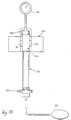
- Figure 9 is a perspective view of a pressure monitor employing a Hall effect sensor for monitoring fluid pressure in a conduit.
- Figure 10 schematically illustrates a calibration system for the pressure sensor and filter chamber.
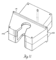
- Figure 11 illustrates in plan view the housing for the pressure of Figure 9 that is mounted on the front panel in Figure 4A.
- Figure 12 illustrates, in schematic form, a plan view of the blood flow through the system components.
- the centrifuge apparatus 10 for the ultra-light plasmapheresis system is illustrated in Figure 1. It should be noted that the apparatus of Fig. 1 is intended to operate when mounted vertically with feet 31 at the bottom and holder 18 at the top.
- a chuck 11 of generally cylindrical shape with a lower inclining wall portion 67 and vertically inclined end wall portion 68 and a longitudinal axis corresponding with the longitudinal axis 8 of the centrifuge is housed within a cylindrical stationary bucket 13.
- the chuck 11 is used to cradle the seamless fluid containing centrifuge bowl described in Figure 3.
- the chuck 11 has an O-ring 12 mounted in groove 6 on the inside of end wall portion 68.
- the O-ring frictionally engages the lower outer surface of an inserted centrifuge bowl (not shown) so that the chuck and bowl will rotationally accelerate together without slippage.
- groove 6 conforms to the outward shape of the bowl at the area of engagement.
- the chuck 11 is mounted onto an adaptor 22 with screws (not shown).
- the adaptor is then rigidly attached to the shaft 9 by retaining nut 21.
- One of these bearings 24 is disposed adjacent the adaptor 22. The bearings are held in place by circlips 23,28.
- a second O-ring 20 is placed between the nut 21 and the chuck 11 to prevent any fluid collecting in the chamber 39 between the outer bucket 13 and the chuck 11 from entering into the motor assembly.
- An outlet port 32 is provided to drain any fluid collecting in the chamber 39 between bucket 13 and chuck 11.
- Shaft 9 threaded at one end to receive nut 21, is rigidly attached to the adaptor 22 and the rotor 25.
- the motor is comprised of stator 26 and rotor 25.
- a tachometer assembly 29 has been placed adjacent the motor to monitor its rotational speed and provide an electrical feed-back signal to control the speed.
- Three cylindrical feet 31 are used to mount the centrifuge into the cabinet base which is further illustrated in Figure 6.
- the longitudinal axis 8 of the centrifuge is hollow from the circular opening 7 in the base of the chuck 11, through the shaft 9, rotor 25, and tachometer assembly 29. This permits the interior to be easily cleaned and also allows air, caused by the insertion of the bowl into the conformably shaped chuck 11 to be expelled, thus permitting easy insertion of the bowl into the chuck.
- a steel ring 15 is affixed to the upper rim of the centrifuge to damp out any excess vibration due to the bowl rotation.
- An outer rim 14 is used to shield or block any liquid from entering the cabinet from around the top of the centrifuge.
- a cover assembly 33, along with associated bowl head holder 18, lock 37 and safety switches 36 are illustrated in both Figures 1 and 2.
- the top view of Fig. 2 shows that the cover assembly 33 is comprised of two symmetric, planar, semi-circular and transparent half-discs 34A and 34B.
- Each half disc 34A and 34B has a separate axis of rotation 35A and 35B, respectively.
- Each half disc rotates in the plane of Figure 2, that is, in a plane orthogonal to centrifuge axis 8.
- the half-discs are rotated in opposite directions to assume an open position for inserting the centrifuge bowl. When closed, both half discs of the cover meet or abut at locking screw 37, which can be tightened by hand to lock the halves in place.
- Each half of cover 33 has a Hall effect sensor 36 attached adjacent to the lock 37.
- a magnet (not shown) is positioned opposite each sensor when both covers are in the closed position.
- Each sensor sends an electrical signal to the control electronics of the system only when each cover is closed. Thus when one or both covers are open the motor is disabled by the main control program of the system.
- the lock screw 37 has a second safety mechanism where the lock must be in the "locked” position and send an electrical signal to the main control program before the system will operate.
- the bowl head holder 18 has a square or rectangular molded inset 38.
- Each half cover 34A and 34B incorporates inset 38.
- Inset 38 engages and clamps a molded panel 53 (Fig. 3B) rigidly attached to the bowl head.
- the shape of the complete inset 38 conforms almost exactly with the shape of the molded panel 53 so that little or no relative movement is possible between the covers 34 and the bowl head during centrifuge operation.
- the disposable bowl assembly of Figures 3A & B is comprised of two basic items: a rotary seal and header assembly 51; and a unitary, seamless, one-piece bowl body 46.
- the seal and header assembly 51 has a feed tube 41 extending from transverse inlet port 49 to provide an inlet path for anticoagulated whole blood into the bottom portion 40B of bowl body 46.
- the shield 52 covers a rotary seal (not shown) and an axial bore which extends from the effluent tube 54 to the outlet port 50.
- the header and seal assembly 51 is mated with bowl body 40 using threads 40F along the upper ring 40G of the bowl.
- the bowl body 40 is an integral body adapted to be manufactured by blow molding or injection blow molding and may be formed of a suitable plastic.
- the bowl body is formed of an upper ring portion 40G, an upper diagonal portion 40E, a middle central portion 40C, a lower diagonal portion 40A, and a bottom cross portion 40B.
- a groove is formed about the periphery of the bowl at 40D to form a holding surface so that the bowl may be used with prior art centrifuge chucks using adaptors to hold the bowl.
- the present centrifuge apparatus could alternatively be mated with a bowl body having a smooth central portion 40C without the peripheral groove 40D, since only the bottom portion 40B of the bowl is frictionally engaged by the chuck.
- An O-ring gasket 48 is disposed on an inner peripheral shoulder of crown member 47 adjacent threads 40F. When member 47 is threaded onto the bowl body 40, gasket 48 is compressed against the upper wall of ring 40G forming a liquid-tight seal.
- a cylindrical walled core 42 is inserted through an opening in ring portion 40G and has a cylindrical outer wall 43 coaxial to the axis of the bowl body 46.
- An upper ring portion 45 of core 42 is adapted to abut the inner wall of ring portion 40G.
- the cabinet used for housing the centrifuge and other system components is illustrated in Figures 4-8.
- the relatively low weight and size of the unit makes this design highly useful for portable applications.
- FIGs 4A and 4B show perspective views of the system as a whole.
- the cover 90 provides access to operator controlled instrumentation. When the cover 90 is closed, a handle 98 rotates to a position above the cabinet for easy transport of the unit. When the cover 90 is open, as illustrated in Figure 4A, it is inclined at an approximate 30° angle for ease of viewing.
- the cover 90 has a panel 91 (see Fig. 7) mounted on the inside of the cover with various display and control functions incorporated therein.
- a liquid crystal display 95 allows monitoring of warnings and control information by the operator.
- Membrane switches 94 allow direct control and programming by the operator of functions or modes of operation, such as Draw, Return, or Stop. Switches 96 control the pump speed and allow it to be varied. Control 97A allows the modification of programmed parameters; and 97B allows selected parameters to be permanently stored.
- a connector 92 provides power to panel 91 through the central portion of the unit.
- the base 70 illustrated in Figure 6 provides support for the installation of the heavier components.
- the centrifuge 75 and card cage 74 are supported by legs 76 affixed to the base 70.
- the main power supply 69 receives power from a standard voltage source through plug 73 and directs power to various system elements including the centrifuge motor 26, the cover display 95, and a pressure sensor mounted in the base with access through the front panel 99 of the cabinet.
- the card cage 74 contains a central microprocessing unit which performs various programmed functions.
- a speaker 79 provides an audible alarm in case of system malfunction.
- a pressure cuff 65 shown in Figure 12 about the arm of the donor is pneumatically connected to a compressor 81 through connector access hole 80.
- a cuff pressure monitor 82 provides feed-back to the control program 64.
- Figure 8 illustrates the central portion and sides of the apparatus along with many of the functional elements.
- Blood is withdrawn from a patient where the flow rate and fluid pressure are measured while the whole blood is transported through tubing to a blood pump 106, and hence into the bowl 40 for centrifuging.
- Donor lights 107 and 112 indicate to the donor the status of his blood flow.
- Optical line sensor 111 provides for the detection of red blood cells in the line after centrifuging.
- Clamp 102 is used to pinch the tubing when the centrifuge is braking to avoid contamination of the plasma by red blood cells.
- the central portion 100 is connected to front 99 and side panels 121 and 122 in Figure 8.
- Each side panel is fitted with handles 119, and holes 120 for receiving the main handle which rotates about the axis through the holes.
- the front panel has apertures for providing operator access to the various monitoring components described above.
- the back panel illustrated in Figure 5, has cooling fans 61 mounted in the center.
- Printed circuit boards 62A and 62B are mounted on each side of the array of fans 61.
- 62B houses the driver electronics of the centrifuge.
- 62A houses the driver electronics of the pumps 105 and 106 and the plasma and donor valves shown in Fig. 12.
- Figures 9-11 illustrate the structure and calibration system for measuring the fluid pressure in a flexibly walled filter chamber through which the blood passes.
- FIG 11 shows the housing 140 for the sensor 130 which can be seen extending from the front panel of the unit in Figure 4A.
- the housing 140 is divided into upper and lower halves 142 which separate to allow access to internal sensor apparatus.
- Panel 141 is used to mount the sensor onto the front panel 99 of the unit.
- the pressure sensor 130 is comprised of two opposed arms 131A and 131B rotatable in a plane orthogonal to the longitudinal axis of axle 132.
- a spring 133 is m4unted between posts 137 imbedded in arms 131 and operates to pull the two arms together.
- a magnet 135 is mounted in arm 131A directly below a Hall effect sensor 134 mounted on the second arm 131B by current carrying fingers 136 extending into the second arm.
- Sensor 134 detects any movement of the two arms 131A and 131B relative to each other due to the resulting change in the magnetic flux of magnet 135 around the sensor 134.
- the sensor 134 generates an electrical signal whose voltage varies with the change in distance between the two arms 131A and 131B.
- Figure 10 illustrates how the sensor 130 is calibrated.
- a hand pump 152 is used to pressurize the interior 154 of the disposable filtration chamber 151.
- the arms 131 of the sensor 130 engage opposite sides of the flexible wall of chamber 154.
- Pressure readings taken from a gauge or standard pressure transducer 153 are matched with electrical signals generated by Hall effect sensor 134 for each pressure level in the chamber.
- the expansion or contraction of the walls of chamber 154 due to the fluid pressure therein is be uniquely identified by the output of the pressure sensor 130 at any time. Thus a unique function is provided by correlating chamber pressure with the voltage of the signal generated by sensor 134.
- Two guides 150 positioned above and below the sensor 134 are used to mount the chamber 151 on the front panel of the cabinet so that the arms 131 are properly aligned about chamber 154.
Landscapes
- Health & Medical Sciences (AREA)
- Vascular Medicine (AREA)
- Heart & Thoracic Surgery (AREA)
- Physics & Mathematics (AREA)
- Anesthesiology (AREA)
- Life Sciences & Earth Sciences (AREA)
- Veterinary Medicine (AREA)
- Engineering & Computer Science (AREA)
- General Physics & Mathematics (AREA)
- Biomedical Technology (AREA)
- Hematology (AREA)
- Cardiology (AREA)
- Animal Behavior & Ethology (AREA)
- General Health & Medical Sciences (AREA)
- Public Health (AREA)
- Electromagnetism (AREA)
- External Artificial Organs (AREA)
- Centrifugal Separators (AREA)
Abstract
Description
- The invention relates generally to apparatus for separating blood or other biological fluids into their constituent components, such as in plasmapheresis or cell washing. Centrifuges have been developed for the purpose of rapidly, efficiently, and inexpensively effecting this separation in a sterile environment.
- It should be noted that while the present system will be described in connection with a plasmapheresis application involving separation of anticoagulated whole blood, other biological fluids and other applications, such as the above-mentioned cell washing process, are contemplated.
- A plasmapheresis process is described in U.S. Patent No. 4,086,924, wherein blood withdrawn from a donor is mixed with an anticoagulant, transported to a rotatable plasmapheresis centrifuge bowl and mounted on a chuck for separation into plasma and non-plasma components. The centrifuge bowl generally comprises a multipiece feed tube and seal assembly with a central input port which introduces whole blood through a longitudinal feed tube into the bottom of the bowl. A central output port is provided to allow the separated plasma to flow out of the bowl. The '924 patent also discloses the use of a standard pressure transducer to monitor fluid pressure in the system.
- These bowls disclosed in the prior art have one or more seams in the bowl where the bowl parts have been welded together. These bowls are not well balanced about the rotational axis and require the use of adaptors for fitting the bowl into the chuck for rotation by a motor. The adaptors are normally lined with an elastomeric material for gripping the bowl.
- Existing centrifuges for blood processing are typically bulky and too heavy for hand-carried, portable use. Systems typically weigh between 80 and 300 pounds and are transported on platforms with rollers. U.S. Patent No. 4,412,831, for example, discloses a centrifuge apparatus transported on rollers. A belt driven gear is used to drive the centrifuge bowl. A flexible bearing mount system is used to ensure alignment of the axis of rotation of the rotor with the changing direction of the rotor's angular momentum vector.
- EP-A-0.257.755 pertains to "PLASMAPHERESIS CENTRIFUGE BOWL" wherein a sealess one-piece bowl body with a rotary seal and header assembly is described. Due to the blow molding process, the balancing of the bowl is maintained within very tight tolerances.
- The present invention comprises a portable centrifuge unit having a light-weight assembly for holding and rotating a disposable, seamless, unitary bowl for plasma separation.
- The bowl is held in a chuck rotated by a motor without the use of adaptors or balancing sleeves. The housing for the centrifuge has a closeable cover with a sensor for indicating that the cover is closed. A lock for securing the cover and means for detecting whether the lock is engaged is also provided.
- The centrifuge system has a hollow longitudinal axis permitting the expelling of air displaced by insertion of the bowl into the chuck. The hollow axis also permits easy cleaning of the centrifuge system.
- The centrifuge system is housed in a portable, light-weight cabinet made of polyester reinforced fiber. The inside bottom of the cabinet has projecting molded platforms for supporting the centrifuge and other heavy instrumentation. Panels on the left and right side are provided with handles for easy transport of the system. The cover folds open with the inside of the cover housing a display and a control switch panel. The cover is inclined at about 30° to permit ease of viewing. With the cover open there is also direct access to the centrifuge, pumps, and control sensors. When the cover is closed it operates to protect components during transport of the unit. A bar handle rotates up over the closed cover to permit carrying by hand. The front panel is provided with an aperture through which a monitor for measuring the flow of blood from a donor is accessed.
- A device for measuring blood pressure in the stream passing through the centrifuge system employs a Hall effect sensor to measure the variation in distance between two displaceable arms which engage the exterior walls of the conduit carrying the flow of blood. A magnet mounted on one arm generates a magnetic field across a Hall effect sensor mounted on the second arm. The position of the sensor with respect to the field changes as the distance between the two arms fluctuates. This variation in the distance between the two arms generates an electrical signal which is calibrated and used to indicate the fluid pressure within the conduit.
- The above and other features of the invention, including various novel details of construction and combinations of parts, will now be more particularly described with reference to the accompanying drawings and pointed out in the claims. It will be understood that the particular plasmapheresis centrifuge embodying the invention is shown by way of illustration only and not as a limitation of the invention. The principles and features of this invention may be employed in varied and numerous embodiments without departing from the scope of the invention.
- Figure 1 is a partial cross-sectional cut-a-way view of the centrifuge rotor and chuck assembly.
- Figure 2 is a top view of the centrifuge of Figure 1 illustrating the cover apparatus.
- Figure 3A is a partial cross-sectional side view of centrifuge bowl and head assembly.
- Figure 3B is a top view of the head assembly of Figure 3A illutrating the molded'panel for holding the head stationary.
- Figure 4A and 4B illustrate, respectively, front and rear perspective views of the cabinet used for housing the centrifuge apparatus.
- Figure 5 illustrates in plan view the back panel with system components of a preferred embodiment mounted thereon.
- Figure 6 illustrates in plan view the base panel used for supporting system components.
- Figure 7 illustrates the in plan view inside surface of the cover with a display panel mounted thereon.
- Figure 8 illustrates in plan view the central portion supported by the front, left, and right side panels.
- Figure 9 is a perspective view of a pressure monitor employing a Hall effect sensor for monitoring fluid pressure in a conduit.
- Figure 10 schematically illustrates a calibration system for the pressure sensor and filter chamber.
- Figure 11 illustrates in plan view the housing for the pressure of Figure 9 that is mounted on the front panel in Figure 4A.
- Figure 12 illustrates, in schematic form, a plan view of the blood flow through the system components.
- The
centrifuge apparatus 10 for the ultra-light plasmapheresis system is illustrated in Figure 1. It should be noted that the apparatus of Fig. 1 is intended to operate when mounted vertically withfeet 31 at the bottom and holder 18 at the top. A chuck 11 of generally cylindrical shape with a lower inclining wall portion 67 and vertically inclined end wall portion 68 and a longitudinal axis corresponding with thelongitudinal axis 8 of the centrifuge is housed within a cylindricalstationary bucket 13. The chuck 11 is used to cradle the seamless fluid containing centrifuge bowl described in Figure 3. - The chuck 11 has an O-
ring 12 mounted ingroove 6 on the inside of end wall portion 68. The O-ring frictionally engages the lower outer surface of an inserted centrifuge bowl (not shown) so that the chuck and bowl will rotationally accelerate together without slippage. In a preferredembodiment groove 6 conforms to the outward shape of the bowl at the area of engagement. The chuck 11 is mounted onto anadaptor 22 with screws (not shown). The adaptor is then rigidly attached to theshaft 9 by retainingnut 21. There are twobearings shaft 9. One of thesebearings 24 is disposed adjacent theadaptor 22. The bearings are held in place bycirclips ring 20 is placed between thenut 21 and the chuck 11 to prevent any fluid collecting in thechamber 39 between theouter bucket 13 and the chuck 11 from entering into the motor assembly. Anoutlet port 32 is provided to drain any fluid collecting in thechamber 39 betweenbucket 13 and chuck 11. -
Shaft 9, threaded at one end to receivenut 21, is rigidly attached to theadaptor 22 and therotor 25. The motor is comprised ofstator 26 androtor 25. - A
tachometer assembly 29 has been placed adjacent the motor to monitor its rotational speed and provide an electrical feed-back signal to control the speed. - Three
cylindrical feet 31 are used to mount the centrifuge into the cabinet base which is further illustrated in Figure 6. - Note that the
longitudinal axis 8 of the centrifuge is hollow from thecircular opening 7 in the base of the chuck 11, through theshaft 9,rotor 25, andtachometer assembly 29. This permits the interior to be easily cleaned and also allows air, caused by the insertion of the bowl into the conformably shaped chuck 11 to be expelled, thus permitting easy insertion of the bowl into the chuck. - A
steel ring 15 is affixed to the upper rim of the centrifuge to damp out any excess vibration due to the bowl rotation. Anouter rim 14 is used to shield or block any liquid from entering the cabinet from around the top of the centrifuge. - A
cover assembly 33, along with associatedbowl head holder 18,lock 37 andsafety switches 36 are illustrated in both Figures 1 and 2. The top view of Fig. 2 shows that thecover assembly 33 is comprised of two symmetric, planar, semi-circular and transparent half-discs 34A and 34B. Eachhalf disc 34A and 34B, has a separate axis of rotation 35A and 35B, respectively. Each half disc rotates in the plane of Figure 2, that is, in a plane orthogonal tocentrifuge axis 8. The half-discs are rotated in opposite directions to assume an open position for inserting the centrifuge bowl. When closed, both half discs of the cover meet or abut at lockingscrew 37, which can be tightened by hand to lock the halves in place. - Two safety mechanisms have been incorporated into the cover apparatus to insure that both cover components are secure during operation. If one or both of the cover halves are not held in place, the
bowl head holder 18 cannot maintain the bowl head 51 (Fig. 3) in a stationary position. This embodiment of the invention requires that the bowl head be stationary for the bowl and centrifuge to separate blood properly. - Each half of
cover 33 has aHall effect sensor 36 attached adjacent to thelock 37. A magnet (not shown) is positioned opposite each sensor when both covers are in the closed position. Each sensor sends an electrical signal to the control electronics of the system only when each cover is closed. Thus when one or both covers are open the motor is disabled by the main control program of the system. - Similarly, the
lock screw 37 has a second safety mechanism where the lock must be in the "locked" position and send an electrical signal to the main control program before the system will operate. - The
bowl head holder 18 has a square or rectangular moldedinset 38. Eachhalf cover 34A and 34B incorporatesinset 38.Inset 38 engages and clamps a molded panel 53 (Fig. 3B) rigidly attached to the bowl head. The shape of thecomplete inset 38 conforms almost exactly with the shape of the moldedpanel 53 so that little or no relative movement is possible between the covers 34 and the bowl head during centrifuge operation. - The disposable bowl assembly of Figures 3A & B is comprised of two basic items: a rotary seal and
header assembly 51; and a unitary, seamless, one-piece bowl body 46. - The seal and
header assembly 51 has afeed tube 41 extending fromtransverse inlet port 49 to provide an inlet path for anticoagulated whole blood into thebottom portion 40B ofbowl body 46. Theshield 52 covers a rotary seal (not shown) and an axial bore which extends from theeffluent tube 54 to theoutlet port 50. - The header and seal
assembly 51 is mated withbowl body 40 usingthreads 40F along theupper ring 40G of the bowl. - The
bowl body 40 is an integral body adapted to be manufactured by blow molding or injection blow molding and may be formed of a suitable plastic. The bowl body is formed of anupper ring portion 40G, an upperdiagonal portion 40E, a middlecentral portion 40C, a lowerdiagonal portion 40A, and abottom cross portion 40B. A groove is formed about the periphery of the bowl at 40D to form a holding surface so that the bowl may be used with prior art centrifuge chucks using adaptors to hold the bowl. The present centrifuge apparatus could alternatively be mated with a bowl body having a smoothcentral portion 40C without theperipheral groove 40D, since only thebottom portion 40B of the bowl is frictionally engaged by the chuck. - An O-
ring gasket 48 is disposed on an inner peripheral shoulder ofcrown member 47adjacent threads 40F. Whenmember 47 is threaded onto thebowl body 40,gasket 48 is compressed against the upper wall ofring 40G forming a liquid-tight seal. - A cylindrical
walled core 42 is inserted through an opening inring portion 40G and has a cylindricalouter wall 43 coaxial to the axis of thebowl body 46. Anupper ring portion 45 ofcore 42 is adapted to abut the inner wall ofring portion 40G. - Blood separation within the
bowl body 46 during centrifuge operation will now be described in general. Whole blood is coupled frominlet port 49 through thefeed tube assembly 41 to the bottom of the spinning centrifuge bowl. The heavier red blood cells are forced radially outward from the central axis and are retained along the inner bowl wall of thecentral portion 40C of the bowl. The lighter, less dense plasma is captured on the outer surface ofcylindrical wall 43 and allowed to exit through theslots 44 at the top ofwall 43 whereupon they pass through theeffluent channel 54 and out through theoutlet port 50. - The cabinet used for housing the centrifuge and other system components is illustrated in Figures 4-8. The relatively low weight and size of the unit makes this design highly useful for portable applications.
- Figures 4A and 4B show perspective views of the system as a whole. The
cover 90 provides access to operator controlled instrumentation. When thecover 90 is closed, ahandle 98 rotates to a position above the cabinet for easy transport of the unit. When thecover 90 is open, as illustrated in Figure 4A, it is inclined at an approximate 30° angle for ease of viewing. Thecover 90 has a panel 91 (see Fig. 7) mounted on the inside of the cover with various display and control functions incorporated therein. Aliquid crystal display 95 allows monitoring of warnings and control information by the operator. Membrane switches 94 allow direct control and programming by the operator of functions or modes of operation, such as Draw, Return, or Stop.Switches 96 control the pump speed and allow it to be varied.Control 97A allows the modification of programmed parameters; and 97B allows selected parameters to be permanently stored. Aconnector 92 provides power topanel 91 through the central portion of the unit. - The base 70 illustrated in Figure 6 provides support for the installation of the heavier components. The
centrifuge 75 andcard cage 74 are supported bylegs 76 affixed to thebase 70. Themain power supply 69 receives power from a standard voltage source throughplug 73 and directs power to various system elements including thecentrifuge motor 26, thecover display 95, and a pressure sensor mounted in the base with access through thefront panel 99 of the cabinet. Thecard cage 74 contains a central microprocessing unit which performs various programmed functions. Aspeaker 79 provides an audible alarm in case of system malfunction. A pressure cuff 65 shown in Figure 12 about the arm of the donor is pneumatically connected to acompressor 81 throughconnector access hole 80. A cuff pressure monitor 82 provides feed-back to the control program 64. - Figure 8 illustrates the central portion and sides of the apparatus along with many of the functional elements. Blood is withdrawn from a patient where the flow rate and fluid pressure are measured while the whole blood is transported through tubing to a
blood pump 106, and hence into thebowl 40 for centrifuging. There are three air detectors, oneprimary 104, and first 113 and second 116 backup detectors. These are used to ensure that the blood plasma is free of air before centrifuging and that blood components returned to the donor after centrifuging are also free of air. -
Donor lights Clamp 102 is used to pinch the tubing when the centrifuge is braking to avoid contamination of the plasma by red blood cells. - There is also an air detector 161 in the path of the anticoagulant as shown in Figure 12 along with anticoagulant bag 160. This anticoagulant is mixed with blood withdrawn through needle 66
- The
central portion 100 is connected tofront 99 and side panels 121 and 122 in Figure 8. Each side panel is fitted withhandles 119, and holes 120 for receiving the main handle which rotates about the axis through the holes. The front panel has apertures for providing operator access to the various monitoring components described above. - The back panel, illustrated in Figure 5, has cooling
fans 61 mounted in the center. Printedcircuit boards fans 61. 62B houses the driver electronics of the centrifuge. 62A houses the driver electronics of thepumps - Figures 9-11 illustrate the structure and calibration system for measuring the fluid pressure in a flexibly walled filter chamber through which the blood passes.
- Figure 11 shows the
housing 140 for thesensor 130 which can be seen extending from the front panel of the unit in Figure 4A. Thehousing 140 is divided into upper andlower halves 142 which separate to allow access to internal sensor apparatus.Panel 141 is used to mount the sensor onto thefront panel 99 of the unit. - The
pressure sensor 130 is comprised of twoopposed arms axle 132. Aspring 133 is m4unted betweenposts 137 imbedded inarms 131 and operates to pull the two arms together. Amagnet 135 is mounted inarm 131A directly below aHall effect sensor 134 mounted on thesecond arm 131B by current carryingfingers 136 extending into the second arm.Sensor 134 detects any movement of the twoarms magnet 135 around thesensor 134. thesensor 134 generates an electrical signal whose voltage varies with the change in distance between the twoarms - Figure 10 illustrates how the
sensor 130 is calibrated. Ahand pump 152 is used to pressurize theinterior 154 of thedisposable filtration chamber 151. Thearms 131 of thesensor 130 engage opposite sides of the flexible wall ofchamber 154. Pressure readings taken from a gauge orstandard pressure transducer 153 are matched with electrical signals generated byHall effect sensor 134 for each pressure level in the chamber. The expansion or contraction of the walls ofchamber 154 due to the fluid pressure therein is be uniquely identified by the output of thepressure sensor 130 at any time. Thus a unique function is provided by correlating chamber pressure with the voltage of the signal generated bysensor 134. - Two guides 150 positioned above and below the
sensor 134 are used to mount thechamber 151 on the front panel of the cabinet so that thearms 131 are properly aligned aboutchamber 154.
Claims (5)
a cylindrical stationary bucket (13) having a closeable top opening,
a centrifuge disposed within said bucket comprising:
Applications Claiming Priority (2)
| Application Number | Priority Date | Filing Date | Title |
|---|---|---|---|
| US93366 | 1987-09-04 | ||
| US07/093,366 US4889524A (en) | 1987-09-04 | 1987-09-04 | Portable centrifuge apparatus |
Publications (2)
| Publication Number | Publication Date |
|---|---|
| EP0394287A1 EP0394287A1 (en) | 1990-10-31 |
| EP0394287B1 true EP0394287B1 (en) | 1992-05-13 |
Family
ID=22238528
Family Applications (1)
| Application Number | Title | Priority Date | Filing Date |
|---|---|---|---|
| EP88907957A Expired - Lifetime EP0394287B1 (en) | 1987-09-04 | 1988-08-23 | Portable centrifuge apparatus |
Country Status (5)
| Country | Link |
|---|---|
| US (1) | US4889524A (en) |
| EP (1) | EP0394287B1 (en) |
| JP (1) | JP2796326B2 (en) |
| DE (1) | DE3871154D1 (en) |
| WO (1) | WO1989001827A1 (en) |
Families Citing this family (63)
| Publication number | Priority date | Publication date | Assignee | Title |
|---|---|---|---|---|
| ATE188387T1 (en) * | 1991-02-08 | 2000-01-15 | Diatide Inc | TECHNETIUM-99M LABELED POLYPEPTIDES FOR IMAGE SHAPING |
| EP0630265B1 (en) * | 1992-03-13 | 2003-04-16 | Diatide, Inc. | TECHNETIUM-99m LABELED PEPTIDES FOR IMAGING INFLAMMATION |
| DE69334033D1 (en) * | 1992-05-21 | 2006-07-27 | Diatide Inc | Technetium-99M labeled peptides for thrombus imaging |
| CH687505A5 (en) * | 1993-01-29 | 1996-12-31 | Elp Rochat | Centrifugal separator for fluids. |
| US5951964A (en) * | 1993-06-04 | 1999-09-14 | Diatide, Inc. | Technetium-99m labeled peptides for imaging |
| US5505683A (en) * | 1993-12-10 | 1996-04-09 | Haemonetics Corporation | Centrifuge bowl gripping apparatus having a retaining arm with a stationary jaw and a moveable jaw |
| US6632191B1 (en) | 1994-10-13 | 2003-10-14 | Haemonetics Corporation | System and method for separating blood components |
| US7332125B2 (en) | 1994-10-13 | 2008-02-19 | Haemonetics Corporation | System and method for processing blood |
| US5651766A (en) * | 1995-06-07 | 1997-07-29 | Transfusion Technologies Corporation | Blood collection and separation system |
| US5733253A (en) * | 1994-10-13 | 1998-03-31 | Transfusion Technologies Corporation | Fluid separation system |
| US5658231A (en) * | 1995-09-21 | 1997-08-19 | Haemonetics Corporation | Mechanism for securing a separation bowl to a mechanical chuck |
| AU6467796A (en) * | 1996-04-24 | 1997-05-15 | Claude Fell | Cell separation system for biological fluids like blood |
| US5924972A (en) * | 1998-03-24 | 1999-07-20 | Turvaville; L. Jackson | Portable D.C. powered centrifuge |
| US6296602B1 (en) | 1999-03-17 | 2001-10-02 | Transfusion Technologies Corporation | Method for collecting platelets and other blood components from whole blood |
| US6629919B2 (en) | 1999-06-03 | 2003-10-07 | Haemonetics Corporation | Core for blood processing apparatus |
| EP1057534A1 (en) | 1999-06-03 | 2000-12-06 | Haemonetics Corporation | Centrifugation bowl with filter core |
| US6679821B1 (en) * | 1999-10-05 | 2004-01-20 | Hitachi Koko Co., Ltd. | Centrifugal separator and administration of user and actual operation of the same |
| US6773389B2 (en) * | 2000-11-02 | 2004-08-10 | Gambro Inc | Fluid separation devices, systems and/or methods using a fluid pressure driven and/or balanced configuration |
| DE60237091D1 (en) | 2001-04-09 | 2010-09-02 | Arteriocyte Medical Systems In | MICROCENTRIFUGE AND DRIVE THEREFOR |
| US20030040835A1 (en) * | 2001-04-28 | 2003-02-27 | Baxter International Inc. | A system and method for managing inventory of blood component collection soft goods in a blood component collection facility |
| US6589153B2 (en) | 2001-09-24 | 2003-07-08 | Medtronic, Inc. | Blood centrifuge with exterior mounted, self-balancing collection chambers |
| US7211037B2 (en) | 2002-03-04 | 2007-05-01 | Therakos, Inc. | Apparatus for the continuous separation of biological fluids into components and method of using same |
| US7479123B2 (en) | 2002-03-04 | 2009-01-20 | Therakos, Inc. | Method for collecting a desired blood component and performing a photopheresis treatment |
| US6982038B2 (en) | 2002-06-14 | 2006-01-03 | Medtronic, Inc. | Centrifuge system utilizing disposable components and automated processing of blood to collect platelet rich plasma |
| US7476209B2 (en) | 2004-12-21 | 2009-01-13 | Therakos, Inc. | Method and apparatus for collecting a blood component and performing a photopheresis treatment |
| US7998052B2 (en) * | 2006-03-07 | 2011-08-16 | Jacques Chammas | Rotor defining a fluid separation chamber of varying volume |
| US8506825B2 (en) * | 2006-11-27 | 2013-08-13 | Sorin Group Italia S.R.L. | Method and apparatus for controlling the flow rate of washing solution during the washing step in a blood centrifugation bowl |
| US8337711B2 (en) | 2008-02-29 | 2012-12-25 | Biomet Biologics, Llc | System and process for separating a material |
| US8454548B2 (en) | 2008-04-14 | 2013-06-04 | Haemonetics Corporation | System and method for plasma reduced platelet collection |
| US8628489B2 (en) | 2008-04-14 | 2014-01-14 | Haemonetics Corporation | Three-line apheresis system and method |
| US8702637B2 (en) | 2008-04-14 | 2014-04-22 | Haemonetics Corporation | System and method for optimized apheresis draw and return |
| EP2138237B1 (en) * | 2008-06-10 | 2011-01-19 | Sorin Group Italia S.r.l. | A securing mechanism, particularly for blood separation centrifuges and the like |
| US8309343B2 (en) | 2008-12-01 | 2012-11-13 | Baxter International Inc. | Apparatus and method for processing biological material |
| US8834402B2 (en) | 2009-03-12 | 2014-09-16 | Haemonetics Corporation | System and method for the re-anticoagulation of platelet rich plasma |
| US9034280B2 (en) * | 2009-12-16 | 2015-05-19 | General Electric Corporation | High-throughput methods and systems for processing biological materials |
| US8808978B2 (en) | 2010-11-05 | 2014-08-19 | Haemonetics Corporation | System and method for automated platelet wash |
| US8317672B2 (en) | 2010-11-19 | 2012-11-27 | Kensey Nash Corporation | Centrifuge method and apparatus |
| US8556794B2 (en) | 2010-11-19 | 2013-10-15 | Kensey Nash Corporation | Centrifuge |
| US20220031925A1 (en) | 2010-11-19 | 2022-02-03 | Dsm Ip Assets B.V. | Centrifuge |
| US8394006B2 (en) | 2010-11-19 | 2013-03-12 | Kensey Nash Corporation | Centrifuge |
| US8469871B2 (en) | 2010-11-19 | 2013-06-25 | Kensey Nash Corporation | Centrifuge |
| US8870733B2 (en) | 2010-11-19 | 2014-10-28 | Kensey Nash Corporation | Centrifuge |
| US9302042B2 (en) | 2010-12-30 | 2016-04-05 | Haemonetics Corporation | System and method for collecting platelets and anticipating plasma return |
| EP2694217B1 (en) | 2011-04-08 | 2018-07-18 | Sorin Group Italia S.r.l. | Disposable device for centrifugal blood separation |
| US11386993B2 (en) | 2011-05-18 | 2022-07-12 | Fenwal, Inc. | Plasma collection with remote programming |
| US12350686B2 (en) * | 2011-11-21 | 2025-07-08 | Pneumatic Scale Corporation | Centrifuge system for separating cells in suspension |
| US11878312B2 (en) * | 2011-11-21 | 2024-01-23 | Pneumatic Scale Corporation | Centrifuge system for separating cells in suspension |
| GB201207178D0 (en) * | 2012-04-24 | 2012-06-06 | Bowyer Andrew | Miniaturised centrifiguration apparatus |
| US8986238B2 (en) | 2012-08-15 | 2015-03-24 | Cyclone Medtech, Inc. | Systems and methods for salvaging red blood cells for autotransfusion |
| CN106413904A (en) | 2014-01-31 | 2017-02-15 | 帝斯曼知识产权资产管理有限公司 | Adipose tissue centrifugation device and method of use |
| US10039876B2 (en) | 2014-04-30 | 2018-08-07 | Sorin Group Italia S.R.L. | System for removing undesirable elements from blood using a first wash step and a second wash step |
| JP6505837B2 (en) * | 2014-10-23 | 2019-04-24 | ソリン・グループ・イタリア・ソシエタ・ア・レスポンサビリタ・リミタータSorin Group Italia S.r.l. | Autologous blood transfusion system for separating fluid components and method of assembling the same |
| US9713810B2 (en) | 2015-03-30 | 2017-07-25 | Biomet Biologics, Llc | Cell washing plunger using centrifugal force |
| US9757721B2 (en) | 2015-05-11 | 2017-09-12 | Biomet Biologics, Llc | Cell washing plunger using centrifugal force |
| US10792416B2 (en) | 2017-05-30 | 2020-10-06 | Haemonetics Corporation | System and method for collecting plasma |
| US10758652B2 (en) | 2017-05-30 | 2020-09-01 | Haemonetics Corporation | System and method for collecting plasma |
| US11065376B2 (en) | 2018-03-26 | 2021-07-20 | Haemonetics Corporation | Plasmapheresis centrifuge bowl |
| US12033750B2 (en) | 2018-05-21 | 2024-07-09 | Fenwal, Inc. | Plasma collection |
| US11412967B2 (en) | 2018-05-21 | 2022-08-16 | Fenwal, Inc. | Systems and methods for plasma collection |
| HUE056564T2 (en) | 2018-05-21 | 2022-02-28 | Fenwal Inc | Systems for optimizing plasma collection volumes |
| US11957998B2 (en) * | 2019-06-06 | 2024-04-16 | Pneumatic Scale Corporation | Centrifuge system for separating cells in suspension |
| TWI760192B (en) * | 2020-12-04 | 2022-04-01 | 笙特科技股份有限公司 | Centrifuge device and lock module |
| CN115849055A (en) * | 2022-10-13 | 2023-03-28 | 上海韩东机械科技有限公司 | Fluid safety chuck |
Citations (1)
| Publication number | Priority date | Publication date | Assignee | Title |
|---|---|---|---|---|
| US257755A (en) * | 1882-05-09 | Portable fence |
Family Cites Families (18)
| Publication number | Priority date | Publication date | Assignee | Title |
|---|---|---|---|---|
| US2019827A (en) * | 1933-07-16 | 1935-11-05 | Kobe Seiko Sho Ltd | Spinning centrifugal motor arrangement |
| US2536793A (en) * | 1945-03-02 | 1951-01-02 | Separator Ab | Sealing device for centrifugal separators |
| US3317127A (en) * | 1945-03-02 | 1967-05-02 | Little Inc A | Centrifuge |
| US3706412A (en) * | 1971-07-28 | 1972-12-19 | Haemonetics Corp | Pressure-actuated centrifuge chuck and centrifuge incorporating the same |
| US3785549A (en) * | 1972-07-31 | 1974-01-15 | Haemonetics Corp | Centrifuge chuck for disposable, snap-in centrifuge rotor |
| US3970245A (en) * | 1975-05-21 | 1976-07-20 | Dr. Molter Gmbh | Universal centrifuge |
| US4010893A (en) * | 1975-06-20 | 1977-03-08 | Becton, Dickinson And Company | Triac centrifuge |
| US4636193A (en) * | 1976-05-14 | 1987-01-13 | Baxter Travenol Laboratories, Inc. | Disposable centrifugal blood processing system |
| US4086924A (en) * | 1976-10-06 | 1978-05-02 | Haemonetics Corporation | Plasmapheresis apparatus |
| US4140268A (en) * | 1977-03-15 | 1979-02-20 | Haemo-Transfer S.A. | Centrifugating device for biological liquids, having a rotatable container, and supporting bracket therefor |
| US4303193A (en) * | 1979-01-22 | 1981-12-01 | Haemonetics Corporation | Apparatus for separating blood into components thereof |
| US4341342A (en) * | 1980-12-04 | 1982-07-27 | Kabushiki Kaisha Kubota Seisakusho | Centrifuge |
| US4412831A (en) * | 1981-07-09 | 1983-11-01 | Haemonetics Corporation | Two plane self-balancing centrifuge |
| US4498532A (en) * | 1983-04-18 | 1985-02-12 | Conoco Inc. | Pump down tool and check valve |
| US4530691A (en) * | 1983-12-13 | 1985-07-23 | Baxter Travenol Laboratories, Inc. | Centrifuge with movable mandrel |
| US4639242A (en) * | 1985-02-04 | 1987-01-27 | Babson Arthur L | Vessel and procedure for automated assay |
| NL94802C (en) * | 1985-10-11 | |||
| DE3771148D1 (en) * | 1986-07-22 | 1991-08-08 | Haemonetics Corp | CENTRIFUGAL HOUSING OR ROTOR FOR PLASMAPHERESE. |
-
1987
- 1987-09-04 US US07/093,366 patent/US4889524A/en not_active Expired - Lifetime
-
1988
- 1988-08-23 DE DE8888907957T patent/DE3871154D1/en not_active Expired - Lifetime
- 1988-08-23 EP EP88907957A patent/EP0394287B1/en not_active Expired - Lifetime
- 1988-08-23 JP JP63508319A patent/JP2796326B2/en not_active Expired - Lifetime
- 1988-08-23 WO PCT/US1988/002964 patent/WO1989001827A1/en not_active Ceased
Patent Citations (1)
| Publication number | Priority date | Publication date | Assignee | Title |
|---|---|---|---|---|
| US257755A (en) * | 1882-05-09 | Portable fence |
Also Published As
| Publication number | Publication date |
|---|---|
| EP0394287A1 (en) | 1990-10-31 |
| US4889524A (en) | 1989-12-26 |
| DE3871154D1 (en) | 1992-06-17 |
| JP2796326B2 (en) | 1998-09-10 |
| JPH04500170A (en) | 1992-01-16 |
| WO1989001827A1 (en) | 1989-03-09 |
Similar Documents
| Publication | Publication Date | Title |
|---|---|---|
| US4889524A (en) | Portable centrifuge apparatus | |
| AU2002327241B2 (en) | Integrated automatic blood collection and processing unit | |
| JP4879016B2 (en) | Blood component separator | |
| EP1011752B1 (en) | Cell processing system and method for controlling it | |
| US6793828B2 (en) | Method of separating and collecting components from a fluid | |
| US6709412B2 (en) | Blood processing systems and methods that employ an in-line leukofilter mounted in a restraining fixture | |
| US9192756B2 (en) | Device intended to break at least one closure element located inside a flexible tube | |
| US6175420B1 (en) | Optical sensors for cell processing systems | |
| AU2002327241A1 (en) | Integrated automatic blood collection and processing unit | |
| US7566315B2 (en) | Blood component collection apparatus and method | |
| AU2009222568B2 (en) | Processing Bag For Component Separator System And Method Of Removing Separated Components | |
| EP0987036B1 (en) | Optical sensors for cell processing systems | |
| CA1048294A (en) | Apparatus for optically analysing a solution | |
| JP2007130283A (en) | Blood component sampling device | |
| JPWO2012144312A1 (en) | Blood component collection device | |
| JP2006271889A (en) | Blood component sampling system | |
| EP4238596B1 (en) | Centrifugal separation and collection of red blood cells or both red blood cells and plasma |
Legal Events
| Date | Code | Title | Description |
|---|---|---|---|
| PUAI | Public reference made under article 153(3) epc to a published international application that has entered the european phase |
Free format text: ORIGINAL CODE: 0009012 |
|
| 17P | Request for examination filed |
Effective date: 19900312 |
|
| AK | Designated contracting states |
Kind code of ref document: A1 Designated state(s): DE FR GB |
|
| 17Q | First examination report despatched |
Effective date: 19910930 |
|
| GRAA | (expected) grant |
Free format text: ORIGINAL CODE: 0009210 |
|
| AK | Designated contracting states |
Kind code of ref document: B1 Designated state(s): DE FR GB |
|
| REF | Corresponds to: |
Ref document number: 3871154 Country of ref document: DE Date of ref document: 19920617 |
|
| ET | Fr: translation filed | ||
| PLBE | No opposition filed within time limit |
Free format text: ORIGINAL CODE: 0009261 |
|
| STAA | Information on the status of an ep patent application or granted ep patent |
Free format text: STATUS: NO OPPOSITION FILED WITHIN TIME LIMIT |
|
| 26N | No opposition filed | ||
| REG | Reference to a national code |
Ref country code: GB Ref legal event code: IF02 |
|
| PGFP | Annual fee paid to national office [announced via postgrant information from national office to epo] |
Ref country code: GB Payment date: 20070830 Year of fee payment: 20 |
|
| PGFP | Annual fee paid to national office [announced via postgrant information from national office to epo] |
Ref country code: DE Payment date: 20071001 Year of fee payment: 20 |
|
| PGFP | Annual fee paid to national office [announced via postgrant information from national office to epo] |
Ref country code: FR Payment date: 20070817 Year of fee payment: 20 |
|
| REG | Reference to a national code |
Ref country code: GB Ref legal event code: PE20 Expiry date: 20080822 |
|
| PG25 | Lapsed in a contracting state [announced via postgrant information from national office to epo] |
Ref country code: GB Free format text: LAPSE BECAUSE OF EXPIRATION OF PROTECTION Effective date: 20080822 |