EP0394285B1 - Optical fiber feedthrough assembly having a ridigizing arrangement therein - Google Patents
Optical fiber feedthrough assembly having a ridigizing arrangement therein Download PDFInfo
- Publication number
- EP0394285B1 EP0394285B1 EP88907899A EP88907899A EP0394285B1 EP 0394285 B1 EP0394285 B1 EP 0394285B1 EP 88907899 A EP88907899 A EP 88907899A EP 88907899 A EP88907899 A EP 88907899A EP 0394285 B1 EP0394285 B1 EP 0394285B1
- Authority
- EP
- European Patent Office
- Prior art keywords
- fiber
- jacket
- sleeve
- tube
- assembly
- Prior art date
- Legal status (The legal status is an assumption and is not a legal conclusion. Google has not performed a legal analysis and makes no representation as to the accuracy of the status listed.)
- Expired - Lifetime
Links
- 239000013307 optical fiber Substances 0.000 title claims description 13
- 239000000835 fiber Substances 0.000 claims abstract description 68
- VYPSYNLAJGMNEJ-UHFFFAOYSA-N silicon dioxide Inorganic materials O=[Si]=O VYPSYNLAJGMNEJ-UHFFFAOYSA-N 0.000 claims abstract description 8
- 239000010453 quartz Substances 0.000 claims abstract description 7
- 230000004323 axial length Effects 0.000 claims abstract 3
- 239000004593 Epoxy Substances 0.000 claims description 11
- 230000000694 effects Effects 0.000 claims description 7
- 239000000463 material Substances 0.000 claims description 7
- 238000005382 thermal cycling Methods 0.000 claims description 6
- 230000003014 reinforcing effect Effects 0.000 claims 1
- 239000003365 glass fiber Substances 0.000 abstract description 5
- 239000011521 glass Substances 0.000 description 14
- 238000012360 testing method Methods 0.000 description 13
- 238000005452 bending Methods 0.000 description 5
- 238000000034 method Methods 0.000 description 5
- 239000002184 metal Substances 0.000 description 3
- NIXOWILDQLNWCW-UHFFFAOYSA-M Acrylate Chemical compound [O-]C(=O)C=C NIXOWILDQLNWCW-UHFFFAOYSA-M 0.000 description 2
- IJGRMHOSHXDMSA-UHFFFAOYSA-N Atomic nitrogen Chemical compound N#N IJGRMHOSHXDMSA-UHFFFAOYSA-N 0.000 description 2
- 239000012298 atmosphere Substances 0.000 description 2
- 238000002788 crimping Methods 0.000 description 2
- 238000012986 modification Methods 0.000 description 2
- 230000004048 modification Effects 0.000 description 2
- 230000003287 optical effect Effects 0.000 description 2
- 230000005693 optoelectronics Effects 0.000 description 2
- 229920001296 polysiloxane Polymers 0.000 description 2
- 230000001681 protective effect Effects 0.000 description 2
- 238000003466 welding Methods 0.000 description 2
- RZVAJINKPMORJF-UHFFFAOYSA-N Acetaminophen Chemical compound CC(=O)NC1=CC=C(O)C=C1 RZVAJINKPMORJF-UHFFFAOYSA-N 0.000 description 1
- 239000004677 Nylon Substances 0.000 description 1
- 239000000853 adhesive Substances 0.000 description 1
- 230000001070 adhesive effect Effects 0.000 description 1
- 238000005336 cracking Methods 0.000 description 1
- 239000000806 elastomer Substances 0.000 description 1
- 229920001971 elastomer Polymers 0.000 description 1
- 230000007613 environmental effect Effects 0.000 description 1
- 230000004927 fusion Effects 0.000 description 1
- 230000009477 glass transition Effects 0.000 description 1
- 239000001307 helium Substances 0.000 description 1
- 229910052734 helium Inorganic materials 0.000 description 1
- SWQJXJOGLNCZEY-UHFFFAOYSA-N helium atom Chemical compound [He] SWQJXJOGLNCZEY-UHFFFAOYSA-N 0.000 description 1
- 229910000833 kovar Inorganic materials 0.000 description 1
- 231100000647 material safety data sheet Toxicity 0.000 description 1
- 238000005259 measurement Methods 0.000 description 1
- 125000005395 methacrylic acid group Chemical group 0.000 description 1
- 230000000116 mitigating effect Effects 0.000 description 1
- 229910052757 nitrogen Inorganic materials 0.000 description 1
- 239000012299 nitrogen atmosphere Substances 0.000 description 1
- 229920001778 nylon Polymers 0.000 description 1
- 230000000149 penetrating effect Effects 0.000 description 1
- 239000004033 plastic Substances 0.000 description 1
- 229920000728 polyester Polymers 0.000 description 1
- 239000005297 pyrex Substances 0.000 description 1
- 238000006748 scratching Methods 0.000 description 1
- 230000002393 scratching effect Effects 0.000 description 1
- 239000005394 sealing glass Substances 0.000 description 1
- 239000004065 semiconductor Substances 0.000 description 1
- 230000035939 shock Effects 0.000 description 1
- 238000005476 soldering Methods 0.000 description 1
- 239000007787 solid Substances 0.000 description 1
- 229910001220 stainless steel Inorganic materials 0.000 description 1
- 239000010935 stainless steel Substances 0.000 description 1
Images
Classifications
-
- G—PHYSICS
- G02—OPTICS
- G02B—OPTICAL ELEMENTS, SYSTEMS OR APPARATUS
- G02B6/00—Light guides; Structural details of arrangements comprising light guides and other optical elements, e.g. couplings
- G02B6/24—Coupling light guides
- G02B6/42—Coupling light guides with opto-electronic elements
- G02B6/4201—Packages, e.g. shape, construction, internal or external details
- G02B6/4248—Feed-through connections for the hermetical passage of fibres through a package wall
-
- G—PHYSICS
- G02—OPTICS
- G02B—OPTICAL ELEMENTS, SYSTEMS OR APPARATUS
- G02B6/00—Light guides; Structural details of arrangements comprising light guides and other optical elements, e.g. couplings
- G02B6/24—Coupling light guides
- G02B6/42—Coupling light guides with opto-electronic elements
- G02B6/4201—Packages, e.g. shape, construction, internal or external details
- G02B6/4219—Mechanical fixtures for holding or positioning the elements relative to each other in the couplings; Alignment methods for the elements, e.g. measuring or observing methods especially used therefor
- G02B6/4236—Fixing or mounting methods of the aligned elements
Definitions
- the present invention relates to a feedthrough assembly for conducting an optical fiber into the interior of a package for an opto-electronic device and, in particular, to such a feedthrough assembly having a rigidizing arrangement therein.
- Opto-electronic communications systems which utilize light energy to transmit intelligence between a transmitting device and a receiving device are known. Exemplary of such systems are those shown in United States Patents 4,119,363 (Camlibel et al.); 4,615,031 (Eales et al.); 4,482,201 (Dousset); 4,456,334 (Henry et al.); 4,360,965 (Fujiwara); and 4,338,577 (Sato et al.); United Kingdom Patents 2,131,971 (Plessey) and 2,124,402 (Standard Telephone and Cables) and EPO Application 181,532 (Siemens).
- Such communications systems typically include a transmitting device utilizing a light source, such as a solid state laser, and a receiving device utilizing a photoresponsive semiconductor.
- the functional elements of both the transmitting device and the receiving device are housed in a hermetically sealed package having a stability leak rate equal to or less than 1 X 10 ⁇ 8 atmospheres cc/sec Helium.
- the fiber is usually supported in a feedthrough assembly comprising a metal sleeve surrounding the fiber.
- the fiber is stripped of its protective jacket for a predetermined distance adjacent its lensed end.
- the sleeve is crimped or otherwise fastened into secure contact with the jacket.
- the lensed end of the optical fiber may project past the end of the metal sleeve.
- the annular region between the inner surface of the sleeve and the exposed outer surface of the fiber is hermetically sealed, as by a glass insert.
- U.K. Patent 1,541,495 standard Telephone and Cable
- United States Patents 4,430,376 Box
- 4,566,892 Ertel
- Each package is provided with an aperture whereby the feedthrough assembly may enter into the interior thereof.
- the feedthrough assembly is appropriately positioned with respect to the package in a suitable relationship with the functional element of the transmitting or receiving device, as the case may be, and thereafter secured, as by laser welding, so as to remain in that selected position.
- US-A-5 222 170 discloses a laser welding method whereby the feedthrough may be secured in the package.
- optical fibre feedthrough assembly of the present invention is defined by claim 1.
- the combination of the tube and the fiber is sufficiently rigid that it is able to withstand at least one, but most preferably, ten thermal cycles from -55 degrees C to 125 degrees C without fracturing so as to still conduct light therethrough.
- the rigidizing member is fabricated from a material, such as quartz, that exhibits thermal characteristics that closely match the thermal characteristics of the fiber.
- the fiber feedthrough assembly generally indicated by reference character 10 includes an outer sleeve 12 fabricated from a suitable weldable material, such as stainless steel, whereby the feedthrough may be mounted in secure attachment to the package of the component of the fiber optic communications system with which the feedthrough assembly is associated.
- the wall of the package is shown in dot-dash lines in the Figure and is indicated by reference character P.
- the package P has an aperture A formed therein through which the feedthrough assembly 10 may enter into the interior of the package P.
- the feedthrough assembly 10 may be secured in an appropriate position with respect to the package as by a weld W.
- the sleeve 12 includes a main tubular portion 14 that tapers, as at 16, adjacent the open end 18 of the sleeve 12 to form a neck portion 20.
- the neck portion 20 exhibits a relatively narrower diameter than that presented by the main tubular portion 14 of the sleeve 10.
- the sleeve 10 is preferably internally narrowed, as at 24.
- a fiber optic cable 30 extends through the sleeve.
- the cable 30 comprises a glass fiber 32 having a protective jacket 34 provided therearound.
- the fiber 32 may be formed from any suitable glass or plastic material.
- a single or a multi-mode silica glass optical fiber cable 30 having an outer diameter of one hundred twenty-five (125) micrometers is preferred.
- the insulating jacket 34 maybe formed of nylon outer buffer layer and having a silicone inner buffer layer. Alternatively the outer buffer layer may be Hytrel® polyester elastomer with the inner buffer layer being acrylate.
- the jacket 34 is stripped from the fiber 32 for a predetermined length near end thereof thereby to define a shoulder or abutment 38.
- the end 40 of the fiber 32 may be lensed, if desired.
- the end 40 of the bare fiber 32 may extend a predetermined distance 42 past the open end 18 of the neck portion 20 of the sleeve 10.
- the jacket 34 of the fiber 30 is fixedly attached, as by crimping, to the sleeve 10, as indicated at 44. As seen from the Figure the crimp 44 is spaced any convenient axial distance behind the shoulder 38.
- the bare fiber 32 is hermetically sealed, as indicated by the reference character 46, to the interior of the sleeve 10 in the vicinity of the neck portion 20.
- Any suitable technique may be used to define the hermetic seal 46, although it is preferred that a glass preform be provided to form the compressive hermetic seal arrangement as disclosed in US-A-5 172 806.
- the preferred candidate glasses for the preform as disclosed in this copending application include Owens-Illinois ESG 1015 glass and Owens-Illinois PP-100 glass.
- a predetermined length 43 of the fiber 32, measured axially with respect to the sleeve 10, is left unsupported between the axially inner end 46E of the seal 46 and the shoulder 38.
- the tendency of the fiber to fracture due to grow out during thermal cycling is reduced.
- the unsupported length 48 of the bare fiber 32 is surrounded by a rigidizing member 50.
- the member 50 has a first end 52 and a second end 54 thereon.
- the member 50 is disposed on the interior of the sleeve such that the end 52 thereof abuts against the inner end 46E of the seal 46.
- the abutting contact between the rigidizing member 50 and the seal 46 may take the form of a mechanical abutment or a fusion abutment in which the material of the seal 46 has wetted to and fused with the rigidizing member 50.
- the second end 54 of the member 50 is disposed in abutting contact with the shoulder 44 of the jacket 34 at the point 58.
- the abutting contact between the member 50 and the shoulder 44 may take any of the following forms.
- the abutting contact may be a simple mechanical abutment, with or without an epoxy fillet weld.
- the abutting contact may be defined with an epoxy cushion between the end of the member 50 and the shoulder 44.
- the abutting contact could be defined with the end 54 of the member 50 penetrating into the inner buffer layer (either silicone or acrylate) of the jacket 34.
- the abutting contact is most preferably formed using the simple mechanical abutment with the epoxy fillet weld.
- Suitable for use as the epoxy in such instance is that Type Light Weld 305 Methacrylic Adhesive such as that sold by Dymax Inc. as MSDS No. 1665. This epoxy is believed suitable for use in the other above-mentioned forms of abutting contact. Also believed suitable for use as the epoxy are those sold by Dymax Inc. as numbers 488, 625 and X13055B.
- the material used to form the rigidizing member 50 is preferably selected so as to closely match the thermal characteristics of the fiber 32. That is to say, the coefficient of thermal expansion of the rigidizing member 50 approximates and, in the most preferred instance, is substantially equal to the coefficient of thermal expansion of the fiber 32.
- the close match of thermal coefficients is desirable in order to prevent relative movement between the rigidizing member 50 and the length 48 of the fiber 32. This close match eliminates the possibility of scratching of the length 48 of the fiber 32 by the rigidizing member 50.
- the rigidizing member 50 is thermally stable at the soldering temperature of the glass preform used to form the seal 46. This temperature is preferably ninety degrees C above the glass transition temperature of the glass preform.
- the rigidizing member 50 takes the form of a quartz tube. It is believed that Pyrex® glass, Kimball KG-33 laboratory glass, Corning 7052 Kovar sealing glass and Owens-Illinois OI ESG 1015 glass may be used for the rigidizing member 50.
- the fiber feedthrough assembly 10 having a rigidizing arrangement therein in accordance with the present invention is subjected to the following sequence of tests. Upon completion of assembly and prior to thermal cycling, each feedthrough assembly 10 is inspected for its ability to conduct light.
- Each feedthrough assembly is then temperature cycled.
- the feedthrough assembly is inserted into an environmental test chamber and thermally cycled between -55 degrees C and 125 degrees C.
- the feedthrough assembly 10 is transferred from a dry nitrogen atmosphere at room temperature into a similar atmosphere at 125 degrees C in a matter of five (5) seconds. It is held at 125 degrees C for ten (10) minutes and then transferred into a dry nitrogen environment at -55 degrees C in a matter of five (5) seconds.
- the feedthrough assembly 10 After ten (10) minutes at -55 degrees C the feedthrough assembly 10 is subjected to a repeated thermal cycling, i.e., it is transferred to the 125 degrees C atmosphere in five (5) seconds and held for ten (10) minutes, then transferred to -55 degrees C in five (5) seconds and held for ten (10) minutes. This hot-to-cold cycle is repeated nine times for a total of ten thermal cycles.
- the feedthrough assembly 10 is tested for shock and vibration.
- the feedthrough assembly 10 having a rigidizing arrangement is then tested for its ability to conduct light.
- the light continuity test used before and after the thermal and vibration tests basically comprises the step of conducting white light through the fiber from the unattached tail end of the fiber through to the lensed end and detecting whether the light is seen emerging from the lensed end of the fiber.
- the first continuity test utilizes a Leitz Wetzler CMM-2D measuring microscope set at 100X magnification. The lensed end of the fiber is faced upwardly toward the objective of the microscope. Light is launched into the fiber from its free (i.e., unlensed) end from a white light source such as that manufactured by Dolan-Jenner Industries Inc., using a General Electric EKE 150 watt, 21 volt projection lamp. If the fiber is continuous a glow is visually detected by an operator against a black field.
- the second continuity test (performed after the thermal and vibration tests) is basically similar.
- a Wild Heerbrugg M3Z microscope set at 40X magnification is used to visually detect a glow against a black field.
- the fiber is positioned in the same manner as discussed.
- the light source in this test is that manufactured byhacker Instruments, Inc. using a General Electric DNF 150 watt, 21 volt projection bulb.
- the second continuity test may be effected without the thermal and/or vibration tests having been performed, or after only some predetermined number of thermal cycles.
- the continuity testing may be done after one thermal cycle, after ten thermal cycles, or some other predetermined number of thermal cycles, whether or not vibration testing is carried out.
- the combination of the rigidizing member 50 and the exposed portion 48 of the fiber has a rigidity associated therewith such that the fiber 32 is able to withstand at least one, ten, or some other predetermined number without fracturing due to grow out of the jacket thermal cycles from -55 degrees C to 125 degrees C and still conduct light therethrough with no more than a twenty percent attentuation.
- product yields after this type of testing as described were less than five (5) percent.
- the presence of the rigidizing member has increased yields by an order of magnitude, i.e., at least 50% yield. Yields of 90% may be achieved.
- the inside diameter of the rigidizing member 50 is closely sized to the outer diameter of the exposed portion 48 of the fiber 32 in order to assist in imparting structural rigidity thereto.
- the rigidizing member 50 in the form of a quartz tube, has an inside diameter of 150 micrometers.
- the outside diameter of the quartz tube is 335 micrometers.
- the area moment of inertia can be increased by increasing the cross sectional area of a member or by changing its shape, e.g., from circular to tubular.
- the addition of the rigidizing member in the form of the quartz tube surrounding the fiber serves to significantly increase the area moment of inertia by increasing the cross sectional area of the combination of the tube 50 and the fiber 32.
- the cross sectional shape of the combination remains circular. It lies within the contemplation of this invention to utilize a rigidizing member 50 that has other than a circular outer diameter so that the cross sectional shape of the combination of the tube 50 and the fiber 32 would differ from the shape of he fiber.
Landscapes
- Physics & Mathematics (AREA)
- General Physics & Mathematics (AREA)
- Optics & Photonics (AREA)
- Optical Couplings Of Light Guides (AREA)
- Light Guides In General And Applications Therefor (AREA)
- Mechanical Coupling Of Light Guides (AREA)
- Manufacture, Treatment Of Glass Fibers (AREA)
- Medicines That Contain Protein Lipid Enzymes And Other Medicines (AREA)
Abstract
Description
- The present invention relates to a feedthrough assembly for conducting an optical fiber into the interior of a package for an opto-electronic device and, in particular, to such a feedthrough assembly having a rigidizing arrangement therein.
- Opto-electronic communications systems which utilize light energy to transmit intelligence between a transmitting device and a receiving device are known. Exemplary of such systems are those shown in United States Patents 4,119,363 (Camlibel et al.); 4,615,031 (Eales et al.); 4,482,201 (Dousset); 4,456,334 (Henry et al.); 4,360,965 (Fujiwara); and 4,338,577 (Sato et al.); United Kingdom Patents 2,131,971 (Plessey) and 2,124,402 (Standard Telephone and Cables) and EPO Application 181,532 (Siemens).
- Such communications systems typically include a transmitting device utilizing a light source, such as a solid state laser, and a receiving device utilizing a photoresponsive semiconductor. The functional elements of both the transmitting device and the receiving device are housed in a hermetically sealed package having a stability leak rate equal to or less than 1 X 10⁻⁸ atmospheres cc/sec Helium.
- The light signals utilized in such systems are conveyed between the transmitting and receiving devices over an optical fiber link. United Kingdom Patents 1,585,899 (Plessey) and 2,150,858 (Standard Telephone and Cable) disclose typical examples of optical fibers useful for this purpose. United States Patent 4,565,558 (Keil et al.) and German Application 3,407,820 (Siemens) both relate to techniques whereby an optical fiber may be provided with a lensed end whereby light energy may be effectively coupled thereinto.
- The fiber is usually supported in a feedthrough assembly comprising a metal sleeve surrounding the fiber. The fiber is stripped of its protective jacket for a predetermined distance adjacent its lensed end. The sleeve is crimped or otherwise fastened into secure contact with the jacket. The lensed end of the optical fiber may project past the end of the metal sleeve. The annular region between the inner surface of the sleeve and the exposed outer surface of the fiber is hermetically sealed, as by a glass insert. U.K. Patent 1,541,495 (standard Telephone and Cable) and United States Patents 4,430,376 (Box) and 4,566,892 (Ertel) all disclose glass to metal seals. US-A-5 177 806 (published 5, Jan. 1993) discloses a feedthrough assembly for an optical fiber having a glass insert that forms a hermetic seal between the fiber and the sleeve. In accordance with this last referenced application all of the stresses on the insert are compressive in nature in order to minimize the tendency of cracking to occur or to propagate.
- Each package is provided with an aperture whereby the feedthrough assembly may enter into the interior thereof. The feedthrough assembly is appropriately positioned with respect to the package in a suitable relationship with the functional element of the transmitting or receiving device, as the case may be, and thereafter secured, as by laser welding, so as to remain in that selected position. US-A-5 222 170 (published on 22, June 1993) discloses a laser welding method whereby the feedthrough may be secured in the package.
- When a situation is presented in which the fiber is attached adjacent one end of its sleeve by a hermetic seal, however formed, and the jacket of the fiber is also attached to the sleeve, as by crimping, there occurs a phenomenon known as "grow out". Grow out is the tendency of the jacket to grow and to contract axially relative to the fiber under thermal cycling so that the portion of the glass fiber intermediate these points of attachment undergoes compressive axial loading which leads to column bending. The bending may be of such a magnitude that the fiber fractures and is thus unable to conduct light energy. It should be understood that the tendency to grow out would occur whatever the form of the hermetic seal and whatever the form of attachment between the jacket and the sleeve. It is known in the art to protect and to support the fiber in the region between these points of attachment with an epoxy material, as disclosed in the above-cited U.S. patent 4,615,031 to Eales et al. By introducing the epoxy into the region between these points of attachment both the fiber and its jacket may be attached to a common support member thereby mitigating the effects of grow out. Because of the small dimensions and close tolerances involved the epoxy is commonly introduced using a vacuum backfill process. It is also known in the art to use epoxy filled glass tubes for forming an optical splice. Exemplary of such a system is the UVC Optical Splice and the Splice for Pigtails (P/N 20126), both sold by Norland Products Inc., New Brunswick, New Jersey.
- In view of the foregoing it is believed advantageous to provide an optical fiber feedthrough assembly that reduces the effects of grow out while avoiding a vacuum backfill process.
- The optical fibre feedthrough assembly of the present invention is defined by claim 1.
- Preferably the combination of the tube and the fiber is sufficiently rigid that it is able to withstand at least one, but most preferably, ten thermal cycles from -55 degrees C to 125 degrees C without fracturing so as to still conduct light therethrough.
- Preferably the rigidizing member is fabricated from a material, such as quartz, that exhibits thermal characteristics that closely match the thermal characteristics of the fiber.
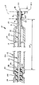
- The invention will be more fully understood from the following detailed description thereof, taken in connection with the accompanying drawing Figure, which forms a part of this application, and which is a side elevational view, entirely in section, of a optical fiber feedthrough assembly in accordance with the present invention.
- The fiber feedthrough assembly generally indicated by
reference character 10 includes anouter sleeve 12 fabricated from a suitable weldable material, such as stainless steel, whereby the feedthrough may be mounted in secure attachment to the package of the component of the fiber optic communications system with which the feedthrough assembly is associated. The wall of the package is shown in dot-dash lines in the Figure and is indicated by reference character P. The package P has an aperture A formed therein through which thefeedthrough assembly 10 may enter into the interior of the package P. Thefeedthrough assembly 10 may be secured in an appropriate position with respect to the package as by a weld W. - The
sleeve 12 includes a maintubular portion 14 that tapers, as at 16, adjacent theopen end 18 of thesleeve 12 to form aneck portion 20. Theneck portion 20 exhibits a relatively narrower diameter than that presented by the maintubular portion 14 of thesleeve 10. For ease of manufacturability thesleeve 10 is preferably internally narrowed, as at 24. - A fiber
optic cable 30 extends through the sleeve. Thecable 30 comprises aglass fiber 32 having aprotective jacket 34 provided therearound. Thefiber 32 may be formed from any suitable glass or plastic material. A single or a multi-mode silica glassoptical fiber cable 30 having an outer diameter of one hundred twenty-five (125) micrometers is preferred. The insulatingjacket 34 maybe formed of nylon outer buffer layer and having a silicone inner buffer layer. Alternatively the outer buffer layer may be Hytrel® polyester elastomer with the inner buffer layer being acrylate. Thejacket 34 is stripped from thefiber 32 for a predetermined length near end thereof thereby to define a shoulder orabutment 38. Theend 40 of thefiber 32 may be lensed, if desired. Theend 40 of thebare fiber 32 may extend apredetermined distance 42 past theopen end 18 of theneck portion 20 of thesleeve 10. Thejacket 34 of thefiber 30 is fixedly attached, as by crimping, to thesleeve 10, as indicated at 44. As seen from the Figure thecrimp 44 is spaced any convenient axial distance behind theshoulder 38. - The
bare fiber 32 is hermetically sealed, as indicated by thereference character 46, to the interior of thesleeve 10 in the vicinity of theneck portion 20. Any suitable technique may be used to define thehermetic seal 46, although it is preferred that a glass preform be provided to form the compressive hermetic seal arrangement as disclosed in US-A-5 172 806. The preferred candidate glasses for the preform as disclosed in this copending application include Owens-Illinois ESG 1015 glass and Owens-Illinois PP-100 glass. A predetermined length 43 of thefiber 32, measured axially with respect to thesleeve 10, is left unsupported between the axiallyinner end 46E of theseal 46 and theshoulder 38. - It is generally well known in this art that in situations where a
fiber 30 is disposed within asleeve 10 and thefiber 30 is securely attached to thesleeve 10 at two axially spaced locations thereon, such as thecrimp point 44 and at the region of thehermetic seal 46, there occurs what is known as "grow out". Grow-out is the tendency of thejacket portion 34 to grow and to contract axially under thermal cycling so that theunsupported length 48 of theglass fiber 32 undergoes compressive axial loading which leads to column bending. The bending may be of such a magnitude that thefiber 32 fractures and is thus unable to conduct light energy. It should be understood that the tendency to grow out would occur whatever the form of thehermetic seal 46 between thefiber 32 and thesleeve 10 and whatever the form of attachment between thejacket 34 and thesleeve 10. - In accordance with this invention the tendency of the fiber to fracture due to grow out during thermal cycling is reduced. To this end the
unsupported length 48 of thebare fiber 32 is surrounded by a rigidizingmember 50. Themember 50 has afirst end 52 and asecond end 54 thereon. Themember 50 is disposed on the interior of the sleeve such that theend 52 thereof abuts against theinner end 46E of theseal 46. The abutting contact between the rigidizingmember 50 and theseal 46 may take the form of a mechanical abutment or a fusion abutment in which the material of theseal 46 has wetted to and fused with the rigidizingmember 50. - The
second end 54 of themember 50 is disposed in abutting contact with theshoulder 44 of thejacket 34 at thepoint 58. The abutting contact between themember 50 and theshoulder 44 may take any of the following forms. The abutting contact may be a simple mechanical abutment, with or without an epoxy fillet weld. The abutting contact may be defined with an epoxy cushion between the end of themember 50 and theshoulder 44. The abutting contact could be defined with theend 54 of themember 50 penetrating into the inner buffer layer (either silicone or acrylate) of thejacket 34. Some of these forms of abutting contact may be combined, if desired, to accommodate for dimensional buildup. The abutting contact is most preferably formed using the simple mechanical abutment with the epoxy fillet weld. Suitable for use as the epoxy in such instance is that Type Light Weld 305 Methacrylic Adhesive such as that sold by Dymax Inc. as MSDS No. 1665. This epoxy is believed suitable for use in the other above-mentioned forms of abutting contact. Also believed suitable for use as the epoxy are those sold by Dymax Inc. as numbers 488, 625 and X13055B. - The material used to form the rigidizing
member 50 is preferably selected so as to closely match the thermal characteristics of thefiber 32. That is to say, the coefficient of thermal expansion of the rigidizingmember 50 approximates and, in the most preferred instance, is substantially equal to the coefficient of thermal expansion of thefiber 32. The close match of thermal coefficients is desirable in order to prevent relative movement between the rigidizingmember 50 and thelength 48 of thefiber 32. This close match eliminates the possibility of scratching of thelength 48 of thefiber 32 by the rigidizingmember 50. - In the preferred case the rigidizing
member 50 is thermally stable at the soldering temperature of the glass preform used to form theseal 46. This temperature is preferably ninety degrees C above the glass transition temperature of the glass preform. - In the preferred case the rigidizing
member 50 takes the form of a quartz tube. It is believed that Pyrex® glass, Kimball KG-33 laboratory glass, Corning 7052 Kovar sealing glass and Owens-Illinois OI ESG 1015 glass may be used for the rigidizingmember 50. - With the rigidizing
member 50 positioned over thelength 48 of thefiber 32 the combination of themember 50 and theglass fiber 32 exhibits a rigidity sufficient to withstand the effects of grow out of thejacket 34 without fracturing. This improved rigidity may be shown as follows. - The
fiber feedthrough assembly 10 having a rigidizing arrangement therein in accordance with the present invention is subjected to the following sequence of tests. Upon completion of assembly and prior to thermal cycling, eachfeedthrough assembly 10 is inspected for its ability to conduct light. - Each feedthrough assembly is then temperature cycled. The feedthrough assembly is inserted into an environmental test chamber and thermally cycled between -55 degrees C and 125 degrees C. Initially the
feedthrough assembly 10 is transferred from a dry nitrogen atmosphere at room temperature into a similar atmosphere at 125 degrees C in a matter of five (5) seconds. It is held at 125 degrees C for ten (10) minutes and then transferred into a dry nitrogen environment at -55 degrees C in a matter of five (5) seconds. After ten (10) minutes at -55 degrees C thefeedthrough assembly 10 is subjected to a repeated thermal cycling, i.e., it is transferred to the 125 degrees C atmosphere in five (5) seconds and held for ten (10) minutes, then transferred to -55 degrees C in five (5) seconds and held for ten (10) minutes. This hot-to-cold cycle is repeated nine times for a total of ten thermal cycles. - After the tenth cycle the
feedthrough assembly 10 is tested for shock and vibration. Thefeedthrough assembly 10 having a rigidizing arrangement is then tested for its ability to conduct light. - The light continuity test used before and after the thermal and vibration tests basically comprises the step of conducting white light through the fiber from the unattached tail end of the fiber through to the lensed end and detecting whether the light is seen emerging from the lensed end of the fiber. The first continuity test utilizes a Leitz Wetzler CMM-2D measuring microscope set at 100X magnification. The lensed end of the fiber is faced upwardly toward the objective of the microscope. Light is launched into the fiber from its free (i.e., unlensed) end from a white light source such as that manufactured by Dolan-Jenner Industries Inc., using a General Electric EKE 150 watt, 21 volt projection lamp. If the fiber is continuous a glow is visually detected by an operator against a black field. It may be desirable to apply some quantitative measurement of the light intensity detected at the lensed end of the fiber as against the ight intensity launched into the fiber tail as a determinant of acceptable fiber continuity. The second continuity test (performed after the thermal and vibration tests) is basically similar. A Wild Heerbrugg M3Z microscope set at 40X magnification is used to visually detect a glow against a black field. The fiber is positioned in the same manner as discussed. The light source in this test is that manufactured by Hacker Instruments, Inc. using a General Electric DNF 150 watt, 21 volt projection bulb.
- The second continuity test may be effected without the thermal and/or vibration tests having been performed, or after only some predetermined number of thermal cycles. For example the continuity testing may be done after one thermal cycle, after ten thermal cycles, or some other predetermined number of thermal cycles, whether or not vibration testing is carried out.
- The combination of the rigidizing
member 50 and the exposedportion 48 of the fiber has a rigidity associated therewith such that thefiber 32 is able to withstand at least one, ten, or some other predetermined number without fracturing due to grow out of the jacket thermal cycles from -55 degrees C to 125 degrees C and still conduct light therethrough with no more than a twenty percent attentuation. Without the rigidizing member of this invention product yields after this type of testing as described were less than five (5) percent. The presence of the rigidizing member has increased yields by an order of magnitude, i.e., at least 50% yield. Yields of 90% may be achieved. - The inside diameter of the rigidizing
member 50 is closely sized to the outer diameter of the exposedportion 48 of thefiber 32 in order to assist in imparting structural rigidity thereto. In the case where the outer diameter of the fiber is 125 micrometers, the rigidizingmember 50, in the form of a quartz tube, has an inside diameter of 150 micrometers. The outside diameter of the quartz tube is 335 micrometers. - It is well known in the art that in order to reduce buckling loads due to column bending, one of the most influential variables is the area moment of inertia. The area moment of inertia can be increased by increasing the cross sectional area of a member or by changing its shape, e.g., from circular to tubular. In this invention the addition of the rigidizing member in the form of the quartz tube surrounding the fiber serves to significantly increase the area moment of inertia by increasing the cross sectional area of the combination of the
tube 50 and thefiber 32. The cross sectional shape of the combination remains circular. It lies within the contemplation of this invention to utilize a rigidizingmember 50 that has other than a circular outer diameter so that the cross sectional shape of the combination of thetube 50 and thefiber 32 would differ from the shape of he fiber. - Those skilled in the art, having the benefit of the teachings of the present invention may effect numerous modifications thereto. It should be understood that these modification as are to be construed as lying within the scope of the present invention, as defined by the appended claims.
Claims (5)
- An optical fiber feedthrough assembly having a sleeve (12), an optical fiber (32) in the sleeve and a seal (46) between the fiber and the sleeve, the fiber having a jacket (34) thereon, the jacket being fixed within the sleeve (12) with a portion of the jacket being removed to define a shoulder (38) such that a predetermined axial length of the fiber between the shoulder (38) and the seal (46) has no jacket, the jacket having the tendency to grow out, that is, extend and contract axially relative to the fiber, in response to thermal cycling whereby the fiber undergoes compressive axial loading and may fracture and become discontinuous,
characterized by
a reinforcing member (50) in the form of a tube which has been arranged within the sleeve (12) to surround and support the predetermined axial length of the fiber (32), whereby the tube is disposed to abut against the shoulder (38) and to abut against the seal (46), the combination of the tube and the fiber thereby having a rigidity associated therewith such that the fiber is able to withstand the effects of grow out without fracturing the unjacketed portion of the fiber (32) thereby being reinforced without having recourse to filling the empty space in the sleeve (12) with epoxy material. - The assembly of claim 1 wherein the combination of the tube and the fiber (32) is able to withstand the effects of grow out of the jacket (34) without fracturing after at least one thermal cycle from -55 °C to 125 °C.
- The assembly of claim 1 wherein the combination of the tube and the fiber (32) is able to withstand the effects of grow out of the jacket (34) without fracturing after at least ten thermal cycles from -55 °C to 125 °C.
- The assembly of one of claims 1-3 wherein the coefficient of thermal expansion of the tube and the coefficient of thermal expansion of the fiber (32) are substantially equal.
- The assembly of one of claims 1-4 wherein the tube is quartz.
Applications Claiming Priority (3)
| Application Number | Priority Date | Filing Date | Title |
|---|---|---|---|
| US07/074,793 US4826276A (en) | 1987-07-17 | 1987-07-17 | Optical fiber feedthrough assembly having a rigidizing arrangement therein |
| PCT/US1988/002464 WO1989000708A1 (en) | 1987-07-17 | 1988-07-14 | Optical fiber feedthrough assembly having a ridigizing arrangement therein |
| US74793 | 2002-02-11 |
Publications (3)
| Publication Number | Publication Date |
|---|---|
| EP0394285A1 EP0394285A1 (en) | 1990-10-31 |
| EP0394285A4 EP0394285A4 (en) | 1991-07-03 |
| EP0394285B1 true EP0394285B1 (en) | 1994-11-30 |
Family
ID=22121730
Family Applications (1)
| Application Number | Title | Priority Date | Filing Date |
|---|---|---|---|
| EP88907899A Expired - Lifetime EP0394285B1 (en) | 1987-07-17 | 1988-07-14 | Optical fiber feedthrough assembly having a ridigizing arrangement therein |
Country Status (7)
| Country | Link |
|---|---|
| US (1) | US4826276A (en) |
| EP (1) | EP0394285B1 (en) |
| JP (1) | JP2703300B2 (en) |
| AT (1) | ATE114828T1 (en) |
| CA (1) | CA1318531C (en) |
| DE (1) | DE3852316T2 (en) |
| WO (1) | WO1989000708A1 (en) |
Families Citing this family (15)
| Publication number | Priority date | Publication date | Assignee | Title |
|---|---|---|---|---|
| US5222170A (en) * | 1987-04-03 | 1993-06-22 | Bt&D Technologies Ltd. | Optical fiber device fabrication |
| EP0337141A1 (en) * | 1988-03-31 | 1989-10-18 | Siemens Aktiengesellschaft | Optical fiber feedthrough for optoelectronic modules and methods of its manufacturing |
| US4911518A (en) * | 1989-03-09 | 1990-03-27 | Amp Incorporated | Threaded front end connector for optical fiber and method of making same |
| US4938558A (en) * | 1989-03-09 | 1990-07-03 | Amp Incorporated | Fused connector for optical fiber |
| US5134280A (en) * | 1990-05-21 | 1992-07-28 | Everett/Charles Contact Products, Inc. | Optical fiber test probe having a sleeve-like plunger movable in a barrel |
| US5325456A (en) * | 1992-02-12 | 1994-06-28 | E.I. Du Pont De Nemours And Company | Optical isolator in an optical fiber feedthrough |
| JP2524463B2 (en) * | 1993-01-29 | 1996-08-14 | 日本電気株式会社 | Airtight sealing method for optical fiber introduction part |
| US6081646A (en) * | 1997-05-27 | 2000-06-27 | Lucent Technologies Inc. | In-line solder seal for optical fiber |
| US6020628A (en) * | 1997-07-21 | 2000-02-01 | Olin Corporation | Optical component package with a hermetic seal |
| US6351593B1 (en) | 1998-11-30 | 2002-02-26 | Three E Laboratories, Inc. | Hermetically sealed connectors and feed-throughs for fiber optic cables and method for effecting hermetic seals for such cables |
| US6321021B1 (en) * | 1999-07-12 | 2001-11-20 | Ocean Design, Inc. | End seal assembly for tubular conduit |
| US10948671B2 (en) * | 2019-03-07 | 2021-03-16 | Applied Optoelectronics, Inc. | Transmitter optical subassembly (TOSA) with laser diode driver (LDD) circuitry mounted to feedthrough of TOSA housing |
| US10928600B2 (en) | 2019-03-07 | 2021-02-23 | Applied Optoelectronics, Inc. | Transmitter optical subassembly (TOSA) with laser diode driver (LDD) circuitry mounted to feedthrough of TOSA housing |
| CN113531220A (en) * | 2020-04-15 | 2021-10-22 | 康普技术有限责任公司 | Cable glands and cable glands |
| DE102020133710B3 (en) * | 2020-12-16 | 2022-02-17 | KRATZER AUTOMATION Aktiengesellschaft | power feed sealing assembly |
Citations (1)
| Publication number | Priority date | Publication date | Assignee | Title |
|---|---|---|---|---|
| US4144504A (en) * | 1976-05-11 | 1979-03-13 | International Standard Electric Corporation | Planar laser mount |
Family Cites Families (24)
| Publication number | Priority date | Publication date | Assignee | Title |
|---|---|---|---|---|
| FR1570259A (en) * | 1967-07-01 | 1969-06-06 | ||
| US4119363A (en) * | 1976-03-18 | 1978-10-10 | Bell Telephone Laboratories Incorporated | Package for optical devices including optical fiber-to-metal hermetic seal |
| GB1541495A (en) * | 1976-05-27 | 1979-03-07 | Standard Telephones Cables Ltd | Coupling optical fibres to optical devices |
| GB1544535A (en) * | 1976-07-29 | 1979-04-19 | Standard Telephones Cables Ltd | Coupling optical fibres |
| DE2737345C2 (en) * | 1976-08-20 | 1991-07-25 | Canon K.K., Tokio/Tokyo | Semiconductor laser device with a Peltier element |
| GB1585899A (en) * | 1977-04-26 | 1981-03-11 | Plessey Co Ltd | Optical fibres |
| JPS5837713B2 (en) * | 1978-12-01 | 1983-08-18 | 富士通株式会社 | Manufacturing method of semiconductor laser device |
| FR2492542A1 (en) * | 1980-09-23 | 1982-04-23 | Thomson Csf | METHOD FOR ALIGNING A GLASS FIBER THAT IS PART OF AN OPTICAL TRANSMISSION CABLE WITH AN OPTOELECTRONIC COMPONENT, ADAPTER, AND COUPLING HEAD COMPRISING THE USE OF THE METHOD |
| FR2503388A1 (en) * | 1981-04-06 | 1982-10-08 | Socapex | CONNECTOR END FOR OPTIC FIBER, METHOD FOR CENTERING FIBER THEREIN AND DEVICE FOR IMPLEMENTING SAID METHOD |
| US4432464A (en) * | 1981-09-09 | 1984-02-21 | Thomas Electronics, Inc. | Large metal cone cathode ray tubes, and envelopes therefor |
| US4430376A (en) * | 1982-07-13 | 1984-02-07 | Box Leonard J | Glass-to-metal compression sealed lead-in structure |
| GB2124402B (en) * | 1982-07-27 | 1986-01-22 | Standard Telephones Cables Ltd | Injection laser packages |
| US4615031A (en) * | 1982-07-27 | 1986-09-30 | International Standard Electric Corporation | Injection laser packages |
| GB2125180A (en) * | 1982-08-10 | 1984-02-29 | Standard Telephones Cables Ltd | Optical fibre manufacture |
| DE3244867A1 (en) * | 1982-12-03 | 1984-06-07 | Siemens AG, 1000 Berlin und 8000 München | TRANSMITTER AND / OR RECEIVING DEVICE FOR ELECTROOPTIC MESSAGE TRANSMISSION DEVICES |
| GB2131971B (en) * | 1982-12-14 | 1986-12-10 | Plessey Co Plc | Positioning an optical fibre relative to an opto-electronic device |
| DE3334565A1 (en) * | 1983-09-23 | 1985-04-04 | Siemens AG, 1000 Berlin und 8000 München | DEVICE FOR PRODUCING CONSTRUCTIONS IN FIBERS |
| DE3337037C2 (en) * | 1983-10-12 | 1985-10-10 | Schott Glaswerke, 6500 Mainz | Board for the production of feedthroughs with glass / metal fusions |
| GB2150858B (en) * | 1983-12-06 | 1986-11-26 | Standard Telephones Cables Ltd | Optical fibres |
| EP0148012B1 (en) * | 1983-12-26 | 1988-11-02 | Kabushiki Kaisha Toshiba | Optical-fiber coupling device |
| DE3405805A1 (en) * | 1984-02-17 | 1985-08-22 | Siemens AG, 1000 Berlin und 8000 München | PROTECTIVE TUBE ARRANGEMENT FOR FIBERGLASS |
| DE3407820A1 (en) * | 1984-03-02 | 1985-11-07 | Siemens AG, 1000 Berlin und 8000 München | Method for producing a fibre taper with a refracting lens |
| US4714315A (en) * | 1984-10-24 | 1987-12-22 | Siemens Aktiengesellschaft | Method for connecting elements of optical communication technology to one another or to elements of releasable plug connections |
| DE3533920A1 (en) * | 1985-09-23 | 1987-03-26 | Siemens Ag | HOLDING DEVICE FOR OPTICAL FIBERS |
-
1987
- 1987-07-17 US US07/074,793 patent/US4826276A/en not_active Expired - Lifetime
-
1988
- 1988-07-14 AT AT88907899T patent/ATE114828T1/en not_active IP Right Cessation
- 1988-07-14 WO PCT/US1988/002464 patent/WO1989000708A1/en not_active Ceased
- 1988-07-14 DE DE3852316T patent/DE3852316T2/en not_active Expired - Fee Related
- 1988-07-14 JP JP63507132A patent/JP2703300B2/en not_active Expired - Fee Related
- 1988-07-14 EP EP88907899A patent/EP0394285B1/en not_active Expired - Lifetime
- 1988-07-15 CA CA000572209A patent/CA1318531C/en not_active Expired - Fee Related
Patent Citations (1)
| Publication number | Priority date | Publication date | Assignee | Title |
|---|---|---|---|---|
| US4144504A (en) * | 1976-05-11 | 1979-03-13 | International Standard Electric Corporation | Planar laser mount |
Also Published As
| Publication number | Publication date |
|---|---|
| DE3852316D1 (en) | 1995-01-12 |
| JPH03501171A (en) | 1991-03-14 |
| WO1989000708A1 (en) | 1989-01-26 |
| EP0394285A4 (en) | 1991-07-03 |
| US4826276A (en) | 1989-05-02 |
| CA1318531C (en) | 1993-06-01 |
| ATE114828T1 (en) | 1994-12-15 |
| EP0394285A1 (en) | 1990-10-31 |
| DE3852316T2 (en) | 1995-05-11 |
| JP2703300B2 (en) | 1998-01-26 |
Similar Documents
| Publication | Publication Date | Title |
|---|---|---|
| US4826276A (en) | Optical fiber feedthrough assembly having a rigidizing arrangement therein | |
| AU634153B2 (en) | T-cell epitope as carriers molecule for conjugate vaccines | |
| US5404415A (en) | Optical fiber coupler and method for preparing same | |
| AU619117B2 (en) | Optical fiber splicing device | |
| US7103257B2 (en) | Hermetically sealed fiber tail assembly for polarization maintaining fiber | |
| US4691985A (en) | Fiber optic connector | |
| US7699535B2 (en) | High energy fiber terminations and methods | |
| US6134360A (en) | Optical fibre sleeve | |
| JPS61163306A (en) | Fiber matching-maintaining apparatus | |
| JPH06222238A (en) | Optical fiber coupler protection structure and protection method | |
| US6931194B2 (en) | Methods and apparatus for forming an optical cable splice | |
| US20090324177A1 (en) | Fiber optic cable splice and cable reconstruction | |
| EP0978739B1 (en) | Optical fiber splice protector and method for applying same | |
| US5455880A (en) | Optical fiber cable connector assembly | |
| US4738505A (en) | Fiber optic cable termination | |
| CN1024951C (en) | Insulator containing optical fiber and manufacturing process thereof | |
| EP0595973B1 (en) | Optical coupler housing | |
| US5384875A (en) | Fiber optic coupler package and packaging method | |
| US20030190135A1 (en) | Hermetic waveguide seals and method of making them | |
| JPH0792335A (en) | Optical fiber hermetically sealed structure | |
| US6895146B1 (en) | Mode scrambler | |
| JPH10300969A (en) | Protective body for fusion spliced part of optical fiber and method of forming the same | |
| JPH06281838A (en) | Protecting cover for single-mode directional coupler | |
| Miller | Mechanical optical fiber splices | |
| CN223179560U (en) | Laser transmission connector and optical fiber detection assembly including the same |
Legal Events
| Date | Code | Title | Description |
|---|---|---|---|
| PUAI | Public reference made under article 153(3) epc to a published international application that has entered the european phase |
Free format text: ORIGINAL CODE: 0009012 |
|
| 17P | Request for examination filed |
Effective date: 19900117 |
|
| AK | Designated contracting states |
Kind code of ref document: A1 Designated state(s): AT BE CH DE FR GB IT LI LU NL SE |
|
| RIN1 | Information on inventor provided before grant (corrected) |
Inventor name: WILLIS, FRANK, MARSDEN Inventor name: JORDAN, BORN ABBOTT, KATHLEEN, SUE |
|
| A4 | Supplementary search report drawn up and despatched |
Effective date: 19910516 |
|
| AK | Designated contracting states |
Kind code of ref document: A4 Designated state(s): AT BE CH DE FR GB IT LI LU NL SE |
|
| RHK1 | Main classification (correction) |
Ipc: G02B 6/42 |
|
| RAP1 | Party data changed (applicant data changed or rights of an application transferred) |
Owner name: BT&D TECHNOLOGIES LIMITED |
|
| 17Q | First examination report despatched |
Effective date: 19930511 |
|
| GRAA | (expected) grant |
Free format text: ORIGINAL CODE: 0009210 |
|
| AK | Designated contracting states |
Kind code of ref document: B1 Designated state(s): AT BE CH DE FR GB IT LI LU NL SE |
|
| PG25 | Lapsed in a contracting state [announced via postgrant information from national office to epo] |
Ref country code: IT Free format text: LAPSE BECAUSE OF FAILURE TO SUBMIT A TRANSLATION OF THE DESCRIPTION OR TO PAY THE FEE WITHIN THE PRE;WARNING: LAPSES OF ITALIAN PATENTS WITH EFFECTIVE DATE BEFORE 2007 MAY HAVE OCCURRED AT ANY TIME BEFORE 2007. THE CORRECT EFFECTIVE DATE MAY BE DIFFERENT FROM THE ONE RECORDED.SCRIBED TIME-LIMIT Effective date: 19941130 Ref country code: AT Effective date: 19941130 Ref country code: NL Effective date: 19941130 Ref country code: LI Effective date: 19941130 Ref country code: CH Effective date: 19941130 Ref country code: BE Effective date: 19941130 |
|
| REF | Corresponds to: |
Ref document number: 114828 Country of ref document: AT Date of ref document: 19941215 Kind code of ref document: T |
|
| REF | Corresponds to: |
Ref document number: 3852316 Country of ref document: DE Date of ref document: 19950112 |
|
| PG25 | Lapsed in a contracting state [announced via postgrant information from national office to epo] |
Ref country code: SE Effective date: 19950228 |
|
| ET | Fr: translation filed | ||
| REG | Reference to a national code |
Ref country code: CH Ref legal event code: PL |
|
| NLV1 | Nl: lapsed or annulled due to failure to fulfill the requirements of art. 29p and 29m of the patents act | ||
| PG25 | Lapsed in a contracting state [announced via postgrant information from national office to epo] |
Ref country code: LU Free format text: LAPSE BECAUSE OF NON-PAYMENT OF DUE FEES Effective date: 19950731 |
|
| PLBE | No opposition filed within time limit |
Free format text: ORIGINAL CODE: 0009261 |
|
| STAA | Information on the status of an ep patent application or granted ep patent |
Free format text: STATUS: NO OPPOSITION FILED WITHIN TIME LIMIT |
|
| 26N | No opposition filed | ||
| PGFP | Annual fee paid to national office [announced via postgrant information from national office to epo] |
Ref country code: FR Payment date: 19990621 Year of fee payment: 12 |
|
| PGFP | Annual fee paid to national office [announced via postgrant information from national office to epo] |
Ref country code: DE Payment date: 19990623 Year of fee payment: 12 |
|
| PG25 | Lapsed in a contracting state [announced via postgrant information from national office to epo] |
Ref country code: FR Free format text: LAPSE BECAUSE OF NON-PAYMENT OF DUE FEES Effective date: 20010330 |
|
| REG | Reference to a national code |
Ref country code: FR Ref legal event code: ST |
|
| PG25 | Lapsed in a contracting state [announced via postgrant information from national office to epo] |
Ref country code: DE Free format text: LAPSE BECAUSE OF NON-PAYMENT OF DUE FEES Effective date: 20010501 |
|
| REG | Reference to a national code |
Ref country code: GB Ref legal event code: IF02 |
|
| REG | Reference to a national code |
Ref country code: GB Ref legal event code: 732E |
|
| PGFP | Annual fee paid to national office [announced via postgrant information from national office to epo] |
Ref country code: GB Payment date: 20020710 Year of fee payment: 15 |
|
| PG25 | Lapsed in a contracting state [announced via postgrant information from national office to epo] |
Ref country code: GB Free format text: LAPSE BECAUSE OF NON-PAYMENT OF DUE FEES Effective date: 20030714 |
|
| GBPC | Gb: european patent ceased through non-payment of renewal fee |
Effective date: 20030714 |