EP0148012B1 - Optical-fiber coupling device - Google Patents
Optical-fiber coupling device Download PDFInfo
- Publication number
- EP0148012B1 EP0148012B1 EP84308995A EP84308995A EP0148012B1 EP 0148012 B1 EP0148012 B1 EP 0148012B1 EP 84308995 A EP84308995 A EP 84308995A EP 84308995 A EP84308995 A EP 84308995A EP 0148012 B1 EP0148012 B1 EP 0148012B1
- Authority
- EP
- European Patent Office
- Prior art keywords
- optical
- fiber
- optical fiber
- coupling
- coupling device
- Prior art date
- Legal status (The legal status is an assumption and is not a legal conclusion. Google has not performed a legal analysis and makes no representation as to the accuracy of the status listed.)
- Expired
Links
Images


Classifications
-
- G—PHYSICS
- G02—OPTICS
- G02B—OPTICAL ELEMENTS, SYSTEMS OR APPARATUS
- G02B6/00—Light guides; Structural details of arrangements comprising light guides and other optical elements, e.g. couplings
- G02B6/24—Coupling light guides
- G02B6/255—Splicing of light guides, e.g. by fusion or bonding
- G02B6/2551—Splicing of light guides, e.g. by fusion or bonding using thermal methods, e.g. fusion welding by arc discharge, laser beam, plasma torch
-
- G—PHYSICS
- G02—OPTICS
- G02B—OPTICAL ELEMENTS, SYSTEMS OR APPARATUS
- G02B6/00—Light guides; Structural details of arrangements comprising light guides and other optical elements, e.g. couplings
- G02B6/24—Coupling light guides
- G02B6/26—Optical coupling means
- G02B6/30—Optical coupling means for use between fibre and thin-film device
-
- G—PHYSICS
- G02—OPTICS
- G02B—OPTICAL ELEMENTS, SYSTEMS OR APPARATUS
- G02B6/00—Light guides; Structural details of arrangements comprising light guides and other optical elements, e.g. couplings
- G02B6/24—Coupling light guides
- G02B6/26—Optical coupling means
- G02B6/32—Optical coupling means having lens focusing means positioned between opposed fibre ends
- G02B6/322—Optical coupling means having lens focusing means positioned between opposed fibre ends and having centering means being part of the lens for the self-positioning of the lightguide at the focal point, e.g. holes, wells, indents, nibs
-
- G—PHYSICS
- G02—OPTICS
- G02B—OPTICAL ELEMENTS, SYSTEMS OR APPARATUS
- G02B6/00—Light guides; Structural details of arrangements comprising light guides and other optical elements, e.g. couplings
- G02B6/24—Coupling light guides
- G02B6/42—Coupling light guides with opto-electronic elements
- G02B6/4201—Packages, e.g. shape, construction, internal or external details
- G02B6/4202—Packages, e.g. shape, construction, internal or external details for coupling an active element with fibres without intermediate optical elements, e.g. fibres with plane ends, fibres with shaped ends, bundles
-
- G—PHYSICS
- G02—OPTICS
- G02B—OPTICAL ELEMENTS, SYSTEMS OR APPARATUS
- G02B6/00—Light guides; Structural details of arrangements comprising light guides and other optical elements, e.g. couplings
- G02B6/24—Coupling light guides
- G02B6/42—Coupling light guides with opto-electronic elements
- G02B6/4201—Packages, e.g. shape, construction, internal or external details
- G02B6/4204—Packages, e.g. shape, construction, internal or external details the coupling comprising intermediate optical elements, e.g. lenses, holograms
- G02B6/4212—Packages, e.g. shape, construction, internal or external details the coupling comprising intermediate optical elements, e.g. lenses, holograms the intermediate optical element being a coupling medium interposed therebetween, e.g. epoxy resin, refractive index matching material, index grease, matching liquid or gel
Definitions
- the present invention relates to an optical-fiber coupling device.
- an optical operation device such as an optical coupler for causing an optical branching or merging, an optical switch for switching an optical transmission line, an optical multi/demul- tiplexer for effecting optical wavelength division multiplexing transmission, etc., as well as an optical transmitter and optical receiver.
- an optical fiber is used in these devices.
- the connecting or coupling of the optical fiber to the optical operation devices is effected by the use of various methods.
- Japanese Patent Disclosure (Kokai) No. 53-55134 discloses a fiber coupling device having a rod lens and an optical fiber. In this case, a resilient member is used for coupling the optical fiber to the rod lens.
- Japanese Patent Disclosure (Kokai) No. 55-15184 discloses an optical-fibre coupler unit wherein a light incident end face of the optical fiber and a glass plate are fixed to each other by means of an epoxy resin having a refractive index substantially equal to that of the optical fiber and glass plate.
- Japanese Patent Disclosure (Kokai) No. 56-147111 discloses an optical-fiber connector unit with a fiber-side connector element to which an optical fiber is fixed, and an element-side connector element to which an optical receiving element is fixed, both said connector elements being detachable. In this case, as seen, a pair of connectors are used for coupling the rod lens and the optical fiber.
- the object of the present invention is to provide an optical-fiber coupling device which prevents misalignment of the axis between an optical fiber and a member to be connected with this optical-fiber.
- the optical fiber coupling device according to claim 1 is provided.
- the optical-fiber coupling device comprises a block onto which light is incident or from which light emerges, an optical fiber, a coupling means for coupling the block and the optical fiber, and a fixing means for fixing the optical fiber. Only a forward end portion of the optical fiber is coupled by the coupling means to a portion of the block at which an optical coupling is to be achieved.
- This coupled section is defined as being a first fiber fixing section.
- a fiber fixing section which fixes a portion of the optical fiber, spaced by a specified distance from the forward end of this optical fiber, is defined as being a second fiber fixing section.
- the second fiber fixing section is fixed directly or indirectly to the block.
- a fiber element portion of the optical fiber is allowed to exist so as to permit this optical fiber to maintain its flexibility.
- the stress applied to the second fiber fixing section is absorbed into the fiber element portion between the first and second fiber fixing sections.
- the stress is prevented from further acting on the forward end of the optical fiber. Accordingly, it is possible to provide an optical-fiber coupling device capable of preventing positional displacements from occurring in the optical-fiber coupling portion due to the application of a mechanical force, and in which rhe optical loss in the coupling portion is very small.
- this optical-fibre coupling device is also excellent in respect to its temperature characteristic.
- An optical fiber 10 is comprised of a fiber element 12 and a nylon jacket 14 for covering the fiber element 12. Only a forward end of the fiber element portion 12, prepared by removing the nylon jacket 14, is coupled to one end of a rod lens 18 by an adhesive agent consisting of, for example, UV curing resin or epoxy resin. Further, the optical fiber element 12 has its part fixed in an optical-fiber fixing section 20, spaced by a specified distance from its forward end, for the purpose of maintaining the flexibility of the optical fiber.
- a protective sleeve 24 In the optical-fiber fixing section 20, that part of the optical fiber element 12 and an immediately succeeding part of the optical fiber 10 covered by the jacket are inserted into a protective sleeve 24 and are adhered to this sleeve 24 by an adhesive agent 22.
- One end of this protective sleeve 24 is inserted into one end of a connecting sleeve 26, which consists of a multi-compound glass, and is bonded thereto by an adhesive agent 28.
- the connecting sleeve 26 is fixed at its other end to a block 30 consisting of an optical glass capable of transmitting at least a light having a specified wavelength in a state wherein the rod lens 18 is inserted thereinto. The other end of the rod lens 18 is fixed to the block 30.
- the optical information transmitted by way of the optical fiber 10 is converted into collimated beams in the rod lens 18.
- the collimated beams are then transmitted through the block 30.
- the block 30 is formed of, for example, borosilicate glass. That part of the optical fiber element 12 which resides between the forward end thereof and the optical-fibre fixing section 20 constitutes an optical fiber element section 32 and is exposed to the air.
- This section 32 is not limited to being exposed to the air, but may be exposed to another gas or fluid. Further, it may be buried within a soft material such as, for example, urethane.
- the characterizing features of this first embodiment are first, that only the forward end of the optical fiber 10 is connected to the rod lens 18 by the adhesive agent 16, and second, that the stress applied to the optical-fiber fixing section 20 is absorbed into the optical-fiber element section 32 located between the forward end of the optical fiber 10 and the fixing section 20 thereof, whereby this stress can be prevented from being exerted upon the forward end of the optical fiber 10. That is to say, the optical fiber element section 32 can be flexed in such a manner as to absorb the stress applied thereto.
- the optical fiber coupling device having the foregoing construction can be manufactured as follows. First, the adhesive agent 16 is fully coated or applied onto one end of the rod lens 18. Then, the optical fiber 10 fixed to the protective sleeve 24 is positioned with respect to the rod lens 18 by use of a center alignment jig. Next, the protective sleeve 24 in which the optical fiber 10 is inserted is adhered or fixed to the block 30 by way of the connecting sleeve 26. When the optical-fiber coupling device is formed in that way, it is possible to couple the optical fiber 10 and the rod lens 18 at one small area without disposing any adhesive agent in the space created between said one end of the protective sleeve 24 and said one end of the rod lens 18.
- the fiber element of the optical fiber element section 32 is flexible. Therefore, the stress, which may result when the adhesive agent 22 in the protective sleeve 24 or the adhesive agent 28 between this protective sleeve 24 and the connecting sleeve 26 is solidified or has its temperature varied, is absorbed into this fiber element 12 because of its flexibility. Accordingly, it is possible to prevent the forward end of the optical fiber 10 from being displaced from the rod lens 18.
- the length of the optical fiber element section 32 is chosen to be about 3 mm or more, then it will be sufficient for preventing such displacement.
- the optimum requirement, which should be satisfied by the length 11 of the rod lens 18 and the length 12 of the optical fiber element section 32, in order to prevent said displacement is shown below.
- af represents the coefficient of linear expansion of the fiber element 12 of the optical-fiber element section 32, and as represents the coefficient of linear expansion of the connecting sleeve 26, the lengths 11 and 12 have only to satisfy the following requirement. That is to say: If this requirement is satisfied, the stress applied to the optical fiber can be substantially zero, independent of temperature variation.
- the rod lens 18 has a linear expansion coefficient of on the assumption that it is formed of glass
- the fiber element 12 of the optical fiber 10 has a linear expansion coefficient of on the assumption that it is formed of silica glass
- the connecting sleeve 26 has a linear expansion coefficient of on the assumption that it is formed of ceramic
- the optical fiber element section 32 will have a length of 12 of 7.1 mm. Therefore, the optical-fiber element section 32 needs to only be set to that length.
- optical-fiber couling device is constructed in the above-mentioned way, even when heat cycles are applied to this coupling device, separation or disconnection becomes less likely to occur in the optical coupling due to the solidification of the adhesive agent. For instance, even when 100 heat cycles each defined between -20°C and +60°C were applied, no disconnection occurred in the optical coupling of the optical-fiber coupling device according to the present invention. In contrast, when heat cycles were also applied to the prior art optical-fiber coupling device having its optical-fiber element section 32 wholly covered by adhesive agent, disconnection occurred in its optical couplings.
- the forward end of the fiber element 12 of the optical fiber 10 is coupled to one end of the rod lens 18 by use of a soldering glass 34.
- the rod lens 18 is first erected vertically, and the soldering glass 34 is fully applied onto the end face of the rod lens 18 in such a manner that it rises therefrom. Then, the soldering glass 34 is heated by means of, for example, a C0 2 laser. Upon heating, the soldering glass 34 is liquefied.
- the fiber element 12 is aligned with the rod lens 18, and then the resultant joined portion is cooled. It should be noted here that if, in this case, the soldering glass 34, fiber element 12 and rod lens 18 have sub- stantiallythe same coefficient of linear expansion, it will sufficiently serve the purpose.
- the other construction is the same as in the first embodiment and, therefore, the same parts or portions and sections are denoted by the same reference numerals, respectively, and a description thereof is omitted.
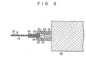
- an optical-fiber coupling device according to a third embodiment of the present invention will be described with reference to Fig. 3.
- the forward end of the fiber element 12 of the optical fiber 10 is bonded to the rod lens 18 by thermal fusion.
- This thermally fused portion is denoted by a reference numeral 36.
- the rod lens 18 and fiber element 12 have substantially the same coefficient of linear expansion, a good thermal fusion will become possible.
- thermal fusion is effected, for example, a C0 2 laser may be used as the heat source.
- the connection which has been achieved by thermal fusion has a merit in that it has higher stability and reliability than the connection which has been achieved by use of an adhesive agent.
- the other construction is the same as in the first embodiment. Therefore, the same parts and sections are denoted by the same reference numerals, and their description is omitted.
- an optical-fiber coupling device according to a fourth embodiment of the present invention will be described with reference to Fig. 4.
- the forward end of this fiber element 12 is inserted into a minute sleeve 38 for fixing the fiber element 12.
- the minute sleeve 38 is formed of multi-compound glass or ceramic.
- the fixation of the minute sleeve 38 to the fiber element 12, as well as the fixation of the minute sleeve 38 to the rod lens 18, is achieved by use of an adhesive agent consisting of epoxy resin.
- the positioning of the fiber element 12 with respect to the rod lens 18 is performed by use of a center alignment jig.
- the inner diameter of the minute sleeve 38 may be of any dimension as long as it is slightly greater than the diameter of the fiber element 12 and yet permits this element 12 to be inclined within the sleeve 38.
- the outer diameter of the minute sleeve 38 may be of any dimension as long as it is not greater than the diameter of the rod lens 18.
- the length of the minute sleeve 38 may be in the range of 0.5 mm to 1.0 mm or so.
- the resultant optical-fiber coupling device advantageously increases in mechanical strength. Further, when the minute sleeve 38 is used, it will be sufficient if only the necessary portions are heated by use of, for example, a nichrome wire. Therefore, it is possible to shorten the time length required for the adhesive agent to harden. Further, the use of the minute sleeve 38 eliminates the necessity of keeping the entire assembling jig at high temperature, so that the working efficiency increases.
- the other construction is the same as in the preceding first embodiment. Therefore, the same parts and sections are denoted by the same reference numerals, and their description is omitted.
- a small hole 40 is formed at the one end portion of the rod lens 18, and the forward end of the fiber element 12 of the optical fiber 10 is secured to this small hole 40 by use of the adhesive agent.
- Such a small hole 40 can be formed in a large number by using, for example, an etching technique. Further, the use of said small hole 40 makes it possible to easily aiign the optical fiber 10.
- Another construction other than that which has been mentioned above is the same as in the first embodiment. Therefore, the same portions and sections are denoted by the same reference numerals, and their description is omitted.
- the optical fiber 10 was coupled to the rod lens 18.
- the optical fiber 10 is coupled to a plate-like block 50 by use of the adhesive agent 16.
- This plate-like block 50 is formed of optical glass consisting of silica glass.
- the block 50 may be formed of sapphire.
- the block 50 may be formed of any other material if it permits the transmission therethrough of at least a light having a specified wavelength.
- the block 50 as shown, is optically coupled to an optical lens 52.
- the other construction is the same as in the first embodiment. Therefore, the same portions and sections are denoted by the same reference numerals, and their description is omitted.
- the optimum requirement which must be satisfied by the length 12 between the forward end of the fiber element 12 and the illustrated rightward end of the protective sleeve 24, is shown below.
- the means whereby the fiber element 12 is coupled to the block 50 is not limited to the adhesive agent 16. Both may be coupled together by using the coupling means shown in the second to fifth embodiments. That is, as shown in Fig. 7, both may be coupled together by use of the minute sleeve 38. Further, as shown in Fig. 8, a small hole 40 may be formed in a thin, dielectric film 54 of Si0 2 that has been provided, for example, by deposition, on the surface of the block 50, thereby to mechanically and optically couple the fiber element 12 to the block 50. Further, as shown in Fig. 9, both may be coupled together by thermal fusion. It should be noted here that the optical lens 52 may be, for example, a rod lens.
- an optical-fiber coupling device according to a seventh embodiment of the present invention will be described with reference to Fig. 10.
- an optical lens mechanism 62 is formed in the plate-like block 60.
- the block 60 containing such an optical lens mechanism 62 can be manufactured by using an ion diffusion technique as in the case of manufacturing, for example, an ordinary rod lens. Further, the block 60 can also be manufactured by burying a sphere lens or rod lens into a plastic body.
- the fiber element 12 of the optical fiber 10 is coupled onto an optical semiconductor element 72 provided on a mounting base 70 consisting of gold-plated kovar.
- the forward end of the fiber element 12 is secured to the optical semiconductor element 72 by use of the adhesive agent 16. This forward end may also be secured thereto by use of the soldering glass.
- the mounting base 70 is secured to a block 74 consisting of gold-plated kovar.
- the optical semiconductor element 72 is connected to lead wires 76a and 76b each consisting of gold-plated kovar.
- the other construction is the same as in the first embodiment. Therefore, the same parts and sections are denoted by the same reference numerals, and their description is omitted.
- the fiber element 12 of the optical fiber 10 may also be secured to the optical semiconductor element 72 via the minute sleeve 38 by the use of an adhesive agent, as shown in the fourth embodiment.
- the optical semiconductor element 72 may be one which functions as a light emitter or one which functions as a light receiver.
- the fiber element 12 is coupled to an optical waveguide 82 formed on the surface of a block 80 consisting of LiNb0 3 .
- the optical waveguide 82 is obtained by diffusing, for example, Ti on the surface of the block 80.
- the optical waveguide 82 is allowed to exist in such a manner that it is sandwiched between the block 80 and an auxiliary block 84 for fixing the same.
- the optical waveguide 82 is not limited to that shown in this embodiment as long as it permits the transmission therethrough of at least a light having a specified wavelength.
- the connecting sleeve 26 is secured to the blocks 80 and 84.
- the fiber element 12 and the optical waveguide 82 are coupled to each other by the adhesive agent 16, as shown.
- the means whereby both are coupled together is not limited to the adhesive agent but may be soldering glass. Further, as shown in Fig. 14, both may be coupled via the minute sleeve 38 by the use of the adhesive agent. Further, as shown in Fig. 15, both may be coupled together by thermal fusion.
- the other construction is the same as in the first embodiment. Therefore, the same parts and sections are denoted by the same reference numerals, and their description is omitted.
- the connecting sleeve 26 of the optical-fiber coupling device shown in Fig. 1 is divided into two parts, i.e., a first portion 26a and a second portion 26b.
- the connecting sleeve 26 is inserted beforehand over the protective sleeve 24, and this protective sleeve 24 is aligned after it is fixed to a center alignment jig.
- the conencting sleeve is divided into the first portion 26a and second portion 26b, since only the first portion 26a has to be inserted over the protective sleeve 24, it is possible to shorten the length of this protective sleeve 24. This offers the advantage of enabling the optical-fiber coupling device to be miniaturized. Further, if the second portion 26b of the connecting sleeve 26 has a precisely made inner diameter and the rod lens 18 is mounted in this second portion 26b, the handling of the rod lens 18 becomes easy.
- optical-fiber coupling device according to an eleventh embodiment of the present invention will be described with reference to Fig. 17.
- two optical fibers 10a and 10b are coupled to the single rod lens 18.
- the two optical fibers 10a and 10b are arranged in proper order within the protective sleeve 24 by the use of an arranging sleeve 90.
- the optical fibers employed are not limited to two in number, but three or more optical fibers may be employed.
- the other construction is the same as in the first embodiment and, therefore, the same parts and sections are denoted by the same reference numerals, respectively, and their description is omitted.
Description
- The present invention relates to an optical-fiber coupling device.
- When it is desired to construct an optical transmission system, it becomes necessary to use various optical operation devices such as an optical coupler for causing an optical branching or merging, an optical switch for switching an optical transmission line, an optical multi/demul- tiplexer for effecting optical wavelength division multiplexing transmission, etc., as well as an optical transmitter and optical receiver. For permitting input or output of optical information, thereby permitting the transmission of this information, an optical fiber is used in these devices. The connecting or coupling of the optical fiber to the optical operation devices is effected by the use of various methods. For example, Japanese Patent Disclosure (Kokai) No. 53-55134 discloses a fiber coupling device having a rod lens and an optical fiber. In this case, a resilient member is used for coupling the optical fiber to the rod lens. Japanese Patent Disclosure (Kokai) No. 55-15184 discloses an optical-fibre coupler unit wherein a light incident end face of the optical fiber and a glass plate are fixed to each other by means of an epoxy resin having a refractive index substantially equal to that of the optical fiber and glass plate. Further, Japanese Patent Disclosure (Kokai) No. 56-147111 discloses an optical-fiber connector unit with a fiber-side connector element to which an optical fiber is fixed, and an element-side connector element to which an optical receiving element is fixed, both said connector elements being detachable. In this case, as seen, a pair of connectors are used for coupling the rod lens and the optical fiber.
- In the above-mentioned prior art optical-fiber coupling unit, respective axes of the opticai fiber and the optical operation device are very likely to be misaligned due to mechanical or thermal displacements of the coupling members, used for coupling the optical fiber, and the members to be connected. This axial misalignment causes optical loss and, at the same time, deteriorates the fiber-insertion loss characteristic (optical loss due to insertion of the optical fiber) of the optical- operation device. Besides, this axial misalignment also raises the problem of decreasing the mechanical stability of the coupling unit. It is also known to provide a distance between the fiber end and the fixing means of the fiber, e.g. from US―A―4 015 894 and from GB-A-2 075 709, Figure 4.
- The object of the present invention is to provide an optical-fiber coupling device which prevents misalignment of the axis between an optical fiber and a member to be connected with this optical-fiber.
- To obtain the above object, the optical fiber coupling device according to claim 1 is provided.
- In the described embodiments of the invention, the optical-fiber coupling device comprises a block onto which light is incident or from which light emerges, an optical fiber, a coupling means for coupling the block and the optical fiber, and a fixing means for fixing the optical fiber. Only a forward end portion of the optical fiber is coupled by the coupling means to a portion of the block at which an optical coupling is to be achieved. This coupled section is defined as being a first fiber fixing section. A fiber fixing section which fixes a portion of the optical fiber, spaced by a specified distance from the forward end of this optical fiber, is defined as being a second fiber fixing section. The second fiber fixing section is fixed directly or indirectly to the block. Between the first and second fiber fixing sections, a fiber element portion of the optical fiber is allowed to exist so as to permit this optical fiber to maintain its flexibility. The stress applied to the second fiber fixing section is absorbed into the fiber element portion between the first and second fiber fixing sections. As a result, the stress is prevented from further acting on the forward end of the optical fiber. Accordingly, it is possible to provide an optical-fiber coupling device capable of preventing positional displacements from occurring in the optical-fiber coupling portion due to the application of a mechanical force, and in which rhe optical loss in the coupling portion is very small. Moreover, this optical-fibre coupling device is also excellent in respect to its temperature characteristic.
- Embodiments of the invention will now be described, by way of example, with reference to the accompanying drawings in which:
- Fig. 1 is a sectional view of an optical-fiber coupling device according to a first embodiment of the present invention; and
- Figs. 2 through 17 are sectional views of optical-fiber coupling devices according to the other embodiments of the present invention.
- A first embodiment of the present invention will now be described with reference to Fig. 1. An
optical fiber 10 is comprised of afiber element 12 and anylon jacket 14 for covering thefiber element 12. Only a forward end of thefiber element portion 12, prepared by removing thenylon jacket 14, is coupled to one end of arod lens 18 by an adhesive agent consisting of, for example, UV curing resin or epoxy resin. Further, theoptical fiber element 12 has its part fixed in an optical-fiber fixing section 20, spaced by a specified distance from its forward end, for the purpose of maintaining the flexibility of the optical fiber. In the optical-fiber fixing section 20, that part of theoptical fiber element 12 and an immediately succeeding part of theoptical fiber 10 covered by the jacket are inserted into aprotective sleeve 24 and are adhered to thissleeve 24 by anadhesive agent 22. One end of thisprotective sleeve 24 is inserted into one end of a connectingsleeve 26, which consists of a multi-compound glass, and is bonded thereto by anadhesive agent 28. The connectingsleeve 26 is fixed at its other end to ablock 30 consisting of an optical glass capable of transmitting at least a light having a specified wavelength in a state wherein therod lens 18 is inserted thereinto. The other end of therod lens 18 is fixed to theblock 30. Accordingly, for example, the optical information transmitted by way of theoptical fiber 10 is converted into collimated beams in therod lens 18. The collimated beams are then transmitted through theblock 30. Theblock 30 is formed of, for example, borosilicate glass. That part of theoptical fiber element 12 which resides between the forward end thereof and the optical-fibre fixing section 20 constitutes an opticalfiber element section 32 and is exposed to the air. Thissection 32 is not limited to being exposed to the air, but may be exposed to another gas or fluid. Further, it may be buried within a soft material such as, for example, urethane. The characterizing features of this first embodiment are first, that only the forward end of theoptical fiber 10 is connected to therod lens 18 by theadhesive agent 16, and second, that the stress applied to the optical-fiber fixing section 20 is absorbed into the optical-fiber element section 32 located between the forward end of theoptical fiber 10 and thefixing section 20 thereof, whereby this stress can be prevented from being exerted upon the forward end of theoptical fiber 10. That is to say, the opticalfiber element section 32 can be flexed in such a manner as to absorb the stress applied thereto. - The optical fiber coupling device having the foregoing construction can be manufactured as follows. First, the
adhesive agent 16 is fully coated or applied onto one end of therod lens 18. Then, theoptical fiber 10 fixed to theprotective sleeve 24 is positioned with respect to therod lens 18 by use of a center alignment jig. Next, theprotective sleeve 24 in which theoptical fiber 10 is inserted is adhered or fixed to theblock 30 by way of the connectingsleeve 26. When the optical-fiber coupling device is formed in that way, it is possible to couple theoptical fiber 10 and therod lens 18 at one small area without disposing any adhesive agent in the space created between said one end of theprotective sleeve 24 and said one end of therod lens 18. In the surrounding area of the opticalfiber element section 32, therefore, no possibility exists of producing stress due to either the solidification or variation in temperature of the adhesive agent; therefore, it is possible to prevent the forward end of theoptical fiber 10 from having its axis displaced from that of therod lens 18. Moreover, the fiber element of the opticalfiber element section 32 is flexible. Therefore, the stress, which may result when theadhesive agent 22 in theprotective sleeve 24 or theadhesive agent 28 between thisprotective sleeve 24 and the connectingsleeve 26 is solidified or has its temperature varied, is absorbed into thisfiber element 12 because of its flexibility. Accordingly, it is possible to prevent the forward end of theoptical fiber 10 from being displaced from therod lens 18. If the length of the opticalfiber element section 32 is chosen to be about 3 mm or more, then it will be sufficient for preventing such displacement. The optimum requirement, which should be satisfied by thelength 11 of therod lens 18 and thelength 12 of the opticalfiber element section 32, in order to prevent said displacement is shown below. When it is now assumed that or represents the coefficient of linear expansion of therod lens 18, af represents the coefficient of linear expansion of thefiber element 12 of the optical-fiber element section 32, and as represents the coefficient of linear expansion of the connectingsleeve 26, thelengths 
rod lens 18 has a linear expansion coefficient of
fiber element 12 of theoptical fiber 10 has a linear expansion coefficient of
sleeve 26 has a linear expansion coefficient of
rod lens 18 has a length of 11=6.5 mm, then the opticalfiber element section 32 will have a length of 12 of 7.1 mm. Therefore, the optical-fiber element section 32 needs to only be set to that length. In the optical fiber coupling device in which the above requirement is satisfied in this way, even when a thermal external force is applied to theprotective sleeve 24, such force will not be extended directly to the forward end of the optical-fiber element section 32 and therod lens 18. Accordingly, such force will not have any undesirable effect upon the quality of the coupling between theoptical fiber 10 and therod lens 18. It should be noted here that in order to make the optical-fiber element section 32 flexible, thissection 32 may be slightly flexed or made spiral beforehand. - If the optical-fiber couling device is constructed in the above-mentioned way, even when heat cycles are applied to this coupling device, separation or disconnection becomes less likely to occur in the optical coupling due to the solidification of the adhesive agent. For instance, even when 100 heat cycles each defined between -20°C and +60°C were applied, no disconnection occurred in the optical coupling of the optical-fiber coupling device according to the present invention. In contrast, when heat cycles were also applied to the prior art optical-fiber coupling device having its optical-
fiber element section 32 wholly covered by adhesive agent, disconnection occurred in its optical couplings. - An optical-fiber coupling device according to a second embodiment of the present invention will now be described with reference to Fig. 2. In this embodiment, the forward end of the
fiber element 12 of theoptical fiber 10 is coupled to one end of therod lens 18 by use of asoldering glass 34. Where, in this way, theoptical fiber 10 is coupled to therod lens 18 by use ofsoldering glass 34, therod lens 18 is first erected vertically, and thesoldering glass 34 is fully applied onto the end face of therod lens 18 in such a manner that it rises therefrom. Then, thesoldering glass 34 is heated by means of, for example, a C02 laser. Upon heating, thesoldering glass 34 is liquefied. Under this condition, thefiber element 12 is aligned with therod lens 18, and then the resultant joined portion is cooled. It should be noted here that if, in this case, thesoldering glass 34,fiber element 12 androd lens 18 have sub- stantiallythe same coefficient of linear expansion, it will sufficiently serve the purpose. The other construction is the same as in the first embodiment and, therefore, the same parts or portions and sections are denoted by the same reference numerals, respectively, and a description thereof is omitted. - Next, an optical-fiber coupling device according to a third embodiment of the present invention will be described with reference to Fig. 3. In this embodiment, the forward end of the
fiber element 12 of theoptical fiber 10 is bonded to therod lens 18 by thermal fusion. This thermally fused portion is denoted by areference numeral 36. If therod lens 18 andfiber element 12 have substantially the same coefficient of linear expansion, a good thermal fusion will become possible. Where thermal fusion is effected, for example, a C02 laser may be used as the heat source. Generally speaking, the connection which has been achieved by thermal fusion has a merit in that it has higher stability and reliability than the connection which has been achieved by use of an adhesive agent. The other construction is the same as in the first embodiment. Therefore, the same parts and sections are denoted by the same reference numerals, and their description is omitted. - Next, an optical-fiber coupling device according to a fourth embodiment of the present invention will be described with reference to Fig. 4. In this embodiment, the forward end of this
fiber element 12 is inserted into aminute sleeve 38 for fixing thefiber element 12. Theminute sleeve 38 is formed of multi-compound glass or ceramic. The fixation of theminute sleeve 38 to thefiber element 12, as well as the fixation of theminute sleeve 38 to therod lens 18, is achieved by use of an adhesive agent consisting of epoxy resin. For materializing this structure, after thefiber element 12 is inserted into theminute sleeve 38, the positioning of thefiber element 12 with respect to therod lens 18 is performed by use of a center alignment jig. Thereafter, thefiber element 12 and therod lens 18 are coupled together with the use of the adhesive agent and theminute sleeve 38. The inner diameter of theminute sleeve 38 may be of any dimension as long as it is slightly greater than the diameter of thefiber element 12 and yet permits thiselement 12 to be inclined within thesleeve 38. On the other hand, the outer diameter of theminute sleeve 38 may be of any dimension as long as it is not greater than the diameter of therod lens 18. Further, the length of theminute sleeve 38 may be in the range of 0.5 mm to 1.0 mm or so. - When the
minute sleeve 38 is used in the above-mentioned way, the resultant optical-fiber coupling device advantageously increases in mechanical strength. Further, when theminute sleeve 38 is used, it will be sufficient if only the necessary portions are heated by use of, for example, a nichrome wire. Therefore, it is possible to shorten the time length required for the adhesive agent to harden. Further, the use of theminute sleeve 38 eliminates the necessity of keeping the entire assembling jig at high temperature, so that the working efficiency increases. The other construction is the same as in the preceding first embodiment. Therefore, the same parts and sections are denoted by the same reference numerals, and their description is omitted. - Next, an optical-fiber coupling device according to a fifth embodiment of the present invention will be described with reference to Fig. 5. In this embodiment, as shown in Fig. 5, a
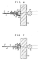
small hole 40 is formed at the one end portion of therod lens 18, and the forward end of thefiber element 12 of theoptical fiber 10 is secured to thissmall hole 40 by use of the adhesive agent. Such asmall hole 40 can be formed in a large number by using, for example, an etching technique. Further, the use of saidsmall hole 40 makes it possible to easily aiign theoptical fiber 10. Another construction other than that which has been mentioned above is the same as in the first embodiment. Therefore, the same portions and sections are denoted by the same reference numerals, and their description is omitted. - Next, an optical-fiber coupling device according to a sixth embodiment of the present invention will be described with reference to Fig. 6. In the first to fifth embodiments, the
optical fiber 10 was coupled to therod lens 18. In this embodiment, however, theoptical fiber 10 is coupled to a plate-like block 50 by use of theadhesive agent 16. This plate-like block 50 is formed of optical glass consisting of silica glass. Theblock 50 may be formed of sapphire. Theblock 50 may be formed of any other material if it permits the transmission therethrough of at least a light having a specified wavelength. Theblock 50, as shown, is optically coupled to anoptical lens 52. The other construction is the same as in the first embodiment. Therefore, the same portions and sections are denoted by the same reference numerals, and their description is omitted. - In the case of the sixth embodiment, the optimum requirement, which must be satisfied by the
length 12 between the forward end of thefiber element 12 and the illustrated rightward end of theprotective sleeve 24, is shown below. When it is now assumed that the rod lens is not provided, the length thereof is zero (i.e., 11 =0) in the above-mentioned formula (1). Therefore, the formula (1) is rewritten such that:
sleeve 26 and thefiber element 12 of the optical-fiber element section 32 be substantially equal to each other. - Note here that the means whereby the
fiber element 12 is coupled to theblock 50 is not limited to theadhesive agent 16. Both may be coupled together by using the coupling means shown in the second to fifth embodiments. That is, as shown in Fig. 7, both may be coupled together by use of theminute sleeve 38. Further, as shown in Fig. 8, asmall hole 40 may be formed in a thin,dielectric film 54 of Si02 that has been provided, for example, by deposition, on the surface of theblock 50, thereby to mechanically and optically couple thefiber element 12 to theblock 50. Further, as shown in Fig. 9, both may be coupled together by thermal fusion. It should be noted here that theoptical lens 52 may be, for example, a rod lens. - Next, an optical-fiber coupling device according to a seventh embodiment of the present invention will be described with reference to Fig. 10. In this embodiment, an
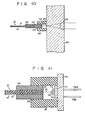
optical lens mechanism 62 is formed in the plate-like block 60. The block 60 containing such anoptical lens mechanism 62 can be manufactured by using an ion diffusion technique as in the case of manufacturing, for example, an ordinary rod lens. Further, the block 60 can also be manufactured by burying a sphere lens or rod lens into a plastic body. When thefiber element 12 is coupled to the plate-like block 60, it is possible to adopt the method of forming thesmall hole 40 shown in the fifth embodiment with respect to the end face of the block 60. When this method is adopted, it becomes easy to align the forward end of thefiber element 12 with respect to thesmall hole 40. - Next, an optical-fiber coupling device according to an eighth embodiment of the present invention will be described with reference to Fig. 11. In this embodiment, the
fiber element 12 of theoptical fiber 10 is coupled onto anoptical semiconductor element 72 provided on a mountingbase 70 consisting of gold-plated kovar. The forward end of thefiber element 12 is secured to theoptical semiconductor element 72 by use of theadhesive agent 16. This forward end may also be secured thereto by use of the soldering glass. The mountingbase 70 is secured to ablock 74 consisting of gold-plated kovar. Theoptical semiconductor element 72 is connected to leadwires 76a and 76b each consisting of gold-plated kovar. The other construction is the same as in the first embodiment. Therefore, the same parts and sections are denoted by the same reference numerals, and their description is omitted. - Note here that as shown in Fig. 12, the
fiber element 12 of theoptical fiber 10 may also be secured to theoptical semiconductor element 72 via theminute sleeve 38 by the use of an adhesive agent, as shown in the fourth embodiment. Theoptical semiconductor element 72 may be one which functions as a light emitter or one which functions as a light receiver. - Next, an optical-fiber coupling device according to a ninth embodiment of the present invention will be described with reference to Fig. 13. In this embodiment, the
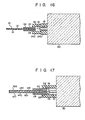
fiber element 12 is coupled to anoptical waveguide 82 formed on the surface of ablock 80 consisting of LiNb03. Theoptical waveguide 82 is obtained by diffusing, for example, Ti on the surface of theblock 80. Theoptical waveguide 82 is allowed to exist in such a manner that it is sandwiched between theblock 80 and anauxiliary block 84 for fixing the same. Theoptical waveguide 82 is not limited to that shown in this embodiment as long as it permits the transmission therethrough of at least a light having a specified wavelength. The connectingsleeve 26 is secured to theblocks fiber element 12 and theoptical waveguide 82 are coupled to each other by theadhesive agent 16, as shown. The means whereby both are coupled together is not limited to the adhesive agent but may be soldering glass. Further, as shown in Fig. 14, both may be coupled via theminute sleeve 38 by the use of the adhesive agent. Further, as shown in Fig. 15, both may be coupled together by thermal fusion. The other construction is the same as in the first embodiment. Therefore, the same parts and sections are denoted by the same reference numerals, and their description is omitted. - Next, an optical-fiber coupling device according to a tenth embodiment of the present invention will be described with reference to Fig. 16. In this embodiment, the connecting
sleeve 26 of the optical-fiber coupling device shown in Fig. 1 is divided into two parts, i.e., a first portion 26a and asecond portion 26b. Usually, when the aligning of theoptical fiber 10 is performed, the connectingsleeve 26 is inserted beforehand over theprotective sleeve 24, and thisprotective sleeve 24 is aligned after it is fixed to a center alignment jig. When, as in this embodiment, the conencting sleeve is divided into the first portion 26a andsecond portion 26b, since only the first portion 26a has to be inserted over theprotective sleeve 24, it is possible to shorten the length of thisprotective sleeve 24. This offers the advantage of enabling the optical-fiber coupling device to be miniaturized. Further, if thesecond portion 26b of the connectingsleeve 26 has a precisely made inner diameter and therod lens 18 is mounted in thissecond portion 26b, the handling of therod lens 18 becomes easy. - Next and finally, an optical-fiber coupling device according to an eleventh embodiment of the present invention will be described with reference to Fig. 17. In this embodiment, two
optical fibers 10a and 10b are coupled to thesingle rod lens 18. The twooptical fibers 10a and 10b are arranged in proper order within theprotective sleeve 24 by the use of an arranging sleeve 90. The optical fibers employed are not limited to two in number, but three or more optical fibers may be employed. The other construction is the same as in the first embodiment and, therefore, the same parts and sections are denoted by the same reference numerals, respectively, and their description is omitted. - As described above, various modifications of the present invention can be obtained without departing from the scope of the invention as claimed.
Claims (14)
Applications Claiming Priority (4)
| Application Number | Priority Date | Filing Date | Title |
|---|---|---|---|
| JP243725/83 | 1983-12-26 | ||
| JP24372583A JPS60135908A (en) | 1983-12-26 | 1983-12-26 | Optical fiber connecting body |
| JP172454/84 | 1984-08-21 | ||
| JP17245484A JPS6151107A (en) | 1984-08-21 | 1984-08-21 | Optical fiber coupler |
Publications (3)
| Publication Number | Publication Date |
|---|---|
| EP0148012A2 EP0148012A2 (en) | 1985-07-10 |
| EP0148012A3 EP0148012A3 (en) | 1986-11-20 |
| EP0148012B1 true EP0148012B1 (en) | 1988-11-02 |
Family
ID=26494804
Family Applications (1)
| Application Number | Title | Priority Date | Filing Date |
|---|---|---|---|
| EP84308995A Expired EP0148012B1 (en) | 1983-12-26 | 1984-12-20 | Optical-fiber coupling device |
Country Status (4)
| Country | Link |
|---|---|
| US (1) | US4779947A (en) |
| EP (1) | EP0148012B1 (en) |
| CA (1) | CA1257795A (en) |
| DE (1) | DE3475011D1 (en) |
Families Citing this family (19)
| Publication number | Priority date | Publication date | Assignee | Title |
|---|---|---|---|---|
| US5177806A (en) * | 1986-12-05 | 1993-01-05 | E. I. Du Pont De Nemours And Company | Optical fiber feedthrough |
| EP0274222B1 (en) * | 1986-12-05 | 1993-03-03 | Bt&D Technologies Limited | Optical fiber feedthrough |
| US4826276A (en) * | 1987-07-17 | 1989-05-02 | E. I. Du Pont De Nemours And Company | Optical fiber feedthrough assembly having a rigidizing arrangement therein |
| US4865410A (en) * | 1988-01-25 | 1989-09-12 | E. I. Du Pont De Nemours And Company | Decoupled fiber optic feedthrough assembly |
| JPH02124504A (en) * | 1988-11-02 | 1990-05-11 | Toshiba Corp | Photodetecting module |
| JP2684219B2 (en) * | 1989-07-05 | 1997-12-03 | 三菱電機株式会社 | Optical semiconductor module |
| JP2570879B2 (en) * | 1990-02-08 | 1997-01-16 | 三菱電機株式会社 | Assembly method of optical semiconductor module |
| US5146526A (en) * | 1991-04-12 | 1992-09-08 | Amoco Corporation | Laser pigtail assembly and method |
| JP2987247B2 (en) * | 1991-12-09 | 1999-12-06 | バーグ・テクノロジー・インコーポレーテッド | Optical fiber connection device |
| US5231684A (en) * | 1992-06-22 | 1993-07-27 | Pdt Systems | Optical fiber microlens |
| GB9217732D0 (en) * | 1992-08-20 | 1992-09-30 | Bt & D Technologies Ltd | Optical devices |
| DE4304762A1 (en) * | 1993-02-17 | 1994-08-18 | Abb Research Ltd | Sensor head for a fiber optic current measuring device |
| US5346583A (en) * | 1993-09-02 | 1994-09-13 | At&T Bell Laboratories | Optical fiber alignment techniques |
| US6106162A (en) * | 1998-11-12 | 2000-08-22 | Delphi Technologies Inc. | Glass optical fiber bundle connector for a hybrid fiber optic lighting distribution system |
| JP3758938B2 (en) * | 1999-06-16 | 2006-03-22 | セイコーエプソン株式会社 | Optical module, method for manufacturing the same, and optical transmission device |
| US6325551B1 (en) | 1999-12-08 | 2001-12-04 | New Focus, Inc. | Method and apparatus for optically aligning optical fibers with optical devices |
| US6632029B1 (en) | 1999-12-22 | 2003-10-14 | New Focus, Inc. | Method & apparatus for packaging high frequency components |
| DE60128360T2 (en) * | 2000-07-28 | 2008-01-10 | Litton Systems, Inc., Woodland Hills | Method for coupling an optical fiber to an optical chip |
| JP3892461B2 (en) * | 2002-07-08 | 2007-03-14 | 独立行政法人科学技術振興機構 | Optical fiber connector, manufacturing method thereof, and optical connecting device |
Family Cites Families (16)
| Publication number | Priority date | Publication date | Assignee | Title |
|---|---|---|---|---|
| GB1454008A (en) * | 1974-03-20 | 1976-10-27 | Pirelli General Cable Works | Communication cables |
| FR2291509A1 (en) * | 1974-11-13 | 1976-06-11 | Cit Alcatel | CONNECTOR FOR OPTICAL FIBERS |
| JPS5355134A (en) * | 1976-10-29 | 1978-05-19 | Komota Giken Kk | Terminal device for optical fiber |
| US4281891A (en) * | 1978-03-27 | 1981-08-04 | Nippon Electric Co., Ltd. | Device for excellently coupling a laser beam to a transmission medium through a lens |
| JPS5515184A (en) * | 1978-07-19 | 1980-02-02 | Nec Corp | Photo coupler |
| GB2026194A (en) * | 1978-07-24 | 1980-01-30 | Gen Electric Co Ltd | Optical fibre coupling |
| JPS5683084A (en) * | 1979-12-10 | 1981-07-07 | Matsushita Electric Works Ltd | Coupling device for light |
| JPS5683710A (en) * | 1979-12-13 | 1981-07-08 | Nippon Telegr & Teleph Corp <Ntt> | Connecting method of optical fiber cable |
| US4296998A (en) * | 1979-12-17 | 1981-10-27 | Bell Telephone Laboratories, Incorporated | Encapsulated light source with coupled fiberguide |
| JPS56147111A (en) * | 1980-04-17 | 1981-11-14 | Matsushita Electric Ind Co Ltd | Photocoupler |
| FR2481815A1 (en) * | 1980-04-30 | 1981-11-06 | Cit Alcatel | OPTO-ELECTRONIC COMPONENT DISCRETE |
| NL8005134A (en) * | 1980-09-12 | 1982-04-01 | Philips Nv | OPTICAL TRANSMISSION SYSTEM. |
| US4433898A (en) * | 1980-12-22 | 1984-02-28 | National Semiconductor Corporation | Fiber optic assembly for coupling an optical fiber and a light source |
| DE3244867A1 (en) * | 1982-12-03 | 1984-06-07 | Siemens AG, 1000 Berlin und 8000 München | TRANSMITTER AND / OR RECEIVING DEVICE FOR ELECTROOPTIC MESSAGE TRANSMISSION DEVICES |
| US4509827A (en) * | 1983-02-02 | 1985-04-09 | The United States Of America As Represented By The United States Secretary Of The Navy | Reproducible standard for aligning fiber optic connectors which employ graded refractive index rod lenses |
| JPS59192219A (en) * | 1983-04-16 | 1984-10-31 | Omron Tateisi Electronics Co | Optical coupling method |
-
1984
- 1984-12-20 EP EP84308995A patent/EP0148012B1/en not_active Expired
- 1984-12-20 DE DE8484308995T patent/DE3475011D1/en not_active Expired
- 1984-12-21 CA CA000470858A patent/CA1257795A/en not_active Expired
- 1984-12-24 US US06/685,799 patent/US4779947A/en not_active Expired - Lifetime
Also Published As
| Publication number | Publication date |
|---|---|
| DE3475011D1 (en) | 1988-12-08 |
| US4779947A (en) | 1988-10-25 |
| EP0148012A3 (en) | 1986-11-20 |
| EP0148012A2 (en) | 1985-07-10 |
| CA1257795A (en) | 1989-07-25 |
Similar Documents
| Publication | Publication Date | Title |
|---|---|---|
| EP0148012B1 (en) | Optical-fiber coupling device | |
| JP3850569B2 (en) | Ferrule assembly and optical module | |
| US5031984A (en) | Optical fiber electro-optical module | |
| US4465335A (en) | Concentric core optical fiber coupler | |
| US7189007B2 (en) | Termination for optic fiber | |
| JP3329797B2 (en) | Method of manufacturing optoelectronic package and integrated mount | |
| USRE34790E (en) | Optical components | |
| US6470117B1 (en) | Compression-molded three-dimensional tapered universal waveguide couplers | |
| JP3259742B2 (en) | Optical waveguide module | |
| KR100302144B1 (en) | connector-type optical transceiver using SOI optical wave-guide | |
| US6567583B2 (en) | Mode converter and method | |
| JP3979185B2 (en) | Optical communication device | |
| US7412148B2 (en) | Optical module including an optical component and an optical device | |
| US20020126962A1 (en) | Brent waveguide for connection to at least one device, adaptive passive alignment features facilitating the connection and associated methods | |
| US5796900A (en) | Apparatus and methods for interconnecting arrays of optical transmission paths employing externally located connector pads | |
| JP2865789B2 (en) | Optical transmission module | |
| US20040247250A1 (en) | Integrated sleeve pluggable package | |
| JP7231045B2 (en) | Optical connector and optical connection structure | |
| JP2002221637A (en) | Optical fiber array and coupling method using this array | |
| JP2005250115A (en) | Optical waveguide module | |
| KR970011147B1 (en) | Method of manufacturing high speed light receiving module | |
| JPH06160673A (en) | Laser module for bi-directional transmission | |
| JPH08110435A (en) | Semiconductor optical coupler | |
| JPH0521206B2 (en) | ||
| JP2003185874A (en) | Optical fiber coupler |
Legal Events
| Date | Code | Title | Description |
|---|---|---|---|
| PUAI | Public reference made under article 153(3) epc to a published international application that has entered the european phase |
Free format text: ORIGINAL CODE: 0009012 |
|
| 17P | Request for examination filed |
Effective date: 19850102 |
|
| AK | Designated contracting states |
Designated state(s): DE FR GB NL |
|
| PUAL | Search report despatched |
Free format text: ORIGINAL CODE: 0009013 |
|
| AK | Designated contracting states |
Kind code of ref document: A3 Designated state(s): DE FR GB NL |
|
| 17Q | First examination report despatched |
Effective date: 19870323 |
|
| GRAA | (expected) grant |
Free format text: ORIGINAL CODE: 0009210 |
|
| AK | Designated contracting states |
Kind code of ref document: B1 Designated state(s): DE FR GB NL |
|
| REF | Corresponds to: |
Ref document number: 3475011 Country of ref document: DE Date of ref document: 19881208 |
|
| ET | Fr: translation filed | ||
| PLBE | No opposition filed within time limit |
Free format text: ORIGINAL CODE: 0009261 |
|
| STAA | Information on the status of an ep patent application or granted ep patent |
Free format text: STATUS: NO OPPOSITION FILED WITHIN TIME LIMIT |
|
| 26N | No opposition filed | ||
| REG | Reference to a national code |
Ref country code: GB Ref legal event code: 746 Effective date: 19980929 |
|
| REG | Reference to a national code |
Ref country code: FR Ref legal event code: D6 |
|
| PGFP | Annual fee paid to national office [announced via postgrant information from national office to epo] |
Ref country code: FR Payment date: 19991208 Year of fee payment: 16 |
|
| PGFP | Annual fee paid to national office [announced via postgrant information from national office to epo] |
Ref country code: GB Payment date: 19991215 Year of fee payment: 16 |
|
| PGFP | Annual fee paid to national office [announced via postgrant information from national office to epo] |
Ref country code: DE Payment date: 19991220 Year of fee payment: 16 |
|
| PGFP | Annual fee paid to national office [announced via postgrant information from national office to epo] |
Ref country code: NL Payment date: 19991228 Year of fee payment: 16 |
|
| PG25 | Lapsed in a contracting state [announced via postgrant information from national office to epo] |
Ref country code: GB Free format text: LAPSE BECAUSE OF NON-PAYMENT OF DUE FEES Effective date: 20001220 |
|
| PG25 | Lapsed in a contracting state [announced via postgrant information from national office to epo] |
Ref country code: NL Free format text: LAPSE BECAUSE OF NON-PAYMENT OF DUE FEES Effective date: 20010701 |
|
| GBPC | Gb: european patent ceased through non-payment of renewal fee |
Effective date: 20001220 |
|
| PG25 | Lapsed in a contracting state [announced via postgrant information from national office to epo] |
Ref country code: FR Free format text: LAPSE BECAUSE OF NON-PAYMENT OF DUE FEES Effective date: 20010831 |
|
| NLV4 | Nl: lapsed or anulled due to non-payment of the annual fee |
Effective date: 20010701 |
|
| REG | Reference to a national code |
Ref country code: FR Ref legal event code: ST |
|
| PG25 | Lapsed in a contracting state [announced via postgrant information from national office to epo] |
Ref country code: DE Free format text: LAPSE BECAUSE OF NON-PAYMENT OF DUE FEES Effective date: 20011002 |