EP0394212B1 - Apparatus and process for the uniform treatment of large quantities of small parts - Google Patents
Apparatus and process for the uniform treatment of large quantities of small parts Download PDFInfo
- Publication number
- EP0394212B1 EP0394212B1 EP90890093A EP90890093A EP0394212B1 EP 0394212 B1 EP0394212 B1 EP 0394212B1 EP 90890093 A EP90890093 A EP 90890093A EP 90890093 A EP90890093 A EP 90890093A EP 0394212 B1 EP0394212 B1 EP 0394212B1
- Authority
- EP
- European Patent Office
- Prior art keywords
- parts
- basket
- treatment
- aggregate
- value
- Prior art date
- Legal status (The legal status is an assumption and is not a legal conclusion. Google has not performed a legal analysis and makes no representation as to the accuracy of the status listed.)
- Expired - Lifetime
Links
Images

Classifications
-
- C—CHEMISTRY; METALLURGY
- C23—COATING METALLIC MATERIAL; COATING MATERIAL WITH METALLIC MATERIAL; CHEMICAL SURFACE TREATMENT; DIFFUSION TREATMENT OF METALLIC MATERIAL; COATING BY VACUUM EVAPORATION, BY SPUTTERING, BY ION IMPLANTATION OR BY CHEMICAL VAPOUR DEPOSITION, IN GENERAL; INHIBITING CORROSION OF METALLIC MATERIAL OR INCRUSTATION IN GENERAL
- C23C—COATING METALLIC MATERIAL; COATING MATERIAL WITH METALLIC MATERIAL; SURFACE TREATMENT OF METALLIC MATERIAL BY DIFFUSION INTO THE SURFACE, BY CHEMICAL CONVERSION OR SUBSTITUTION; COATING BY VACUUM EVAPORATION, BY SPUTTERING, BY ION IMPLANTATION OR BY CHEMICAL VAPOUR DEPOSITION, IN GENERAL
- C23C24/00—Coating starting from inorganic powder
- C23C24/02—Coating starting from inorganic powder by application of pressure only
- C23C24/04—Impact or kinetic deposition of particles
- C23C24/045—Impact or kinetic deposition of particles by trembling using impacting inert media
-
- B—PERFORMING OPERATIONS; TRANSPORTING
- B01—PHYSICAL OR CHEMICAL PROCESSES OR APPARATUS IN GENERAL
- B01J—CHEMICAL OR PHYSICAL PROCESSES, e.g. CATALYSIS OR COLLOID CHEMISTRY; THEIR RELEVANT APPARATUS
- B01J2/00—Processes or devices for granulating materials, e.g. fertilisers in general; Rendering particulate materials free flowing in general, e.g. making them hydrophobic
- B01J2/006—Coating of the granules without description of the process or the device by which the granules are obtained
-
- B—PERFORMING OPERATIONS; TRANSPORTING
- B05—SPRAYING OR ATOMISING IN GENERAL; APPLYING FLUENT MATERIALS TO SURFACES, IN GENERAL
- B05C—APPARATUS FOR APPLYING FLUENT MATERIALS TO SURFACES, IN GENERAL
- B05C3/00—Apparatus in which the work is brought into contact with a bulk quantity of liquid or other fluent material
- B05C3/02—Apparatus in which the work is brought into contact with a bulk quantity of liquid or other fluent material the work being immersed in the liquid or other fluent material
- B05C3/04—Apparatus in which the work is brought into contact with a bulk quantity of liquid or other fluent material the work being immersed in the liquid or other fluent material with special provision for agitating the work or the liquid or other fluent material
- B05C3/08—Apparatus in which the work is brought into contact with a bulk quantity of liquid or other fluent material the work being immersed in the liquid or other fluent material with special provision for agitating the work or the liquid or other fluent material the work and the liquid or other fluent material being agitated together in a container, e.g. tumbled
-
- B—PERFORMING OPERATIONS; TRANSPORTING
- B05—SPRAYING OR ATOMISING IN GENERAL; APPLYING FLUENT MATERIALS TO SURFACES, IN GENERAL
- B05D—PROCESSES FOR APPLYING FLUENT MATERIALS TO SURFACES, IN GENERAL
- B05D1/00—Processes for applying liquids or other fluent materials
-
- C—CHEMISTRY; METALLURGY
- C23—COATING METALLIC MATERIAL; COATING MATERIAL WITH METALLIC MATERIAL; CHEMICAL SURFACE TREATMENT; DIFFUSION TREATMENT OF METALLIC MATERIAL; COATING BY VACUUM EVAPORATION, BY SPUTTERING, BY ION IMPLANTATION OR BY CHEMICAL VAPOUR DEPOSITION, IN GENERAL; INHIBITING CORROSION OF METALLIC MATERIAL OR INCRUSTATION IN GENERAL
- C23G—CLEANING OR DE-GREASING OF METALLIC MATERIAL BY CHEMICAL METHODS OTHER THAN ELECTROLYSIS
- C23G3/00—Apparatus for cleaning or pickling metallic material
-
- B—PERFORMING OPERATIONS; TRANSPORTING
- B05—SPRAYING OR ATOMISING IN GENERAL; APPLYING FLUENT MATERIALS TO SURFACES, IN GENERAL
- B05D—PROCESSES FOR APPLYING FLUENT MATERIALS TO SURFACES, IN GENERAL
- B05D2258/00—Small objects (e.g. screws)
Definitions
- the present invention relates to an apparatus and method for mass treatment of small parts in a manner such that a substantially uniform exposure of all accessible surfaces of such parts to a treating medium is achieved.
- the invention relates to an apparatus for the uniform treatment, e.g. wetting or drying, of the surfaces of a plurality of individual parts when such parts constitute a randomly oriented aggregate, comprising a basket for holding said aggregate of parts to be treated, means for rotating said basket about an axis with at least two different rotational speeds, an inclined bottom surface and a sidewall, outlet means in said sidewall to allow exit of a treatment fluid, in conformity with the introductory part of claim 1.
- a further aspect relates to a method for the uniform treatment, e.g. wetting or drying, of the surfaces of a plurality of individual parts when such parts constitute a randomly oriented aggregate, comprising at least the following steps:
- the orientation of the axis of rotation of the vessel of the centrifuge is changed from vertical to inclined and back to vertical.
- the centrifuge works in a conventional manner with relative high speed of rotation (step one and step three).
- the centrifuge works as a scouring tumbler with low speed or medium speed (step two).
- a cleaning agent is added.
- the greater part of the cleaning agent is discharged and a medium speed is imparted to the rotating vessel.
- treatment is used to mean that the entire part including all accessible internal and external surfaces is changed, modified or affected.
- typical treatments include electroplating, electroless plating, etching, pickling, passivating, reducing, rinsing, washing, drying, soaking, cleaning, coating, diffusion and the like.
- a fluid some type of treatment medium
- the fluid is a liquid, such as an aqueous or organic solution which may be acidic or basic with or without the addition of other chemicals or agents therein. It is also contemplated that the fluid be a gas or mixture of gasses.
- the volume of the electrolyte containing the nickel compound would be in a varying degree deprived of its active potential as it passes into, between, through or around the parts. This results in a thin deposit on some surfaces while the more accessible surfaces on the outermost parts will interact with electrolyte having a normal potency rate so that a thicker deposit will be achieved there. Surfaces which experience a normal exchange rate would have a predictable deposit thickness proportional to the time the parts are immersed in the electroless nickel bath. If the thickness of deposit on these accessible surfaces is desired to be thin (i.e., on the order of about 2 to 3 micrometers), the coating throughout small openings may be insufficient to allow a coherent, non-porous deposit which is required to achieve corrosion shielding.
- the present invention provides a method and apparatus for substantially reducing these problems so that a uniform treatment of all surfaces of such parts can be achieved.
- This invention relates to an apparatus and to methods for the uniform treatment of the surfaces of a plurality of individual parts in conformity to the characterizing parts of the independent claims 1, 7, 8 and 12.
- the method comprises introducing the parts into a vessel or basket where they form an aggregate; introducing a treatment medium into the vessel; and repeatedly separating, dispersing and expanding the parts from the aggregate and then returning the parts back to the aggregate during controlled cycles so that all surfaces of the parts to be treated are exposed to and contacted by the treatment medium. While the parts are separated and dispersed from the aggregate, the treatment medium is forced into, around, through and out from the parts so that after a number of cycles, all surfaces of the parts are uniformly treated by the treatment medium, since all have had a chance to be in proper orientation relative to the treatment medium.
- the vessel is rotated at a speed sufficient to separate and disperse the parts due to centrifugal force.
- the rotation of the vessel induces the parts to travel from a first position in a lower portion of the vessel in a radially outward and upward direction towards a second position where the parts are retained and restricted from further outward and upward movement while the medium is urged by the prevailing centrifugal force to move radially outwardly through small peripheral openings in the vessel sidewall adjacent the parts where they have been restricted by the vessel from further outward movement by the centrifugal force.
- the speed of rotation of the vessel can be reduced to allow the parts to return to the first position along the inclined bottom surface of the vessel.
- the speed of rotation of the vessel can be repeatedly increased and reduced so as to alternately move the parts between the first and second positions, thus eventually positioning and orienting all surfaces of all parts for contact with the treating medium so as to obtain a uniform treatment of such surfaces.
- the vessel is immersed in the treatment medium, and during rotation the treatment medium enters the vessel through openings in the vessel bottom surface or through other suitable means before it exits the vessel through small openings provided at a maximum diameter in a vessel sidewall adjacent the second position where the parts are retained during rotation of the vessel. It is also possible to remove all of the treatment medium from the parts by removing the vessel from the treatment medium and by repeatedly rotating and stopping the rotation of the vessel, thus allowing the parts to return back to the aggregate shape after the vessel is removed from the treatment medium. Centrifugal force would then urge the treatment medium away from the surfaces of the parts and out of the vessel through the sidewall openings.
- the vessel is introduced into a first treatment medium where the parts are treated as noted above, the vessel is then removed from the first treatment medium and the medium is removed from the parts after the treatment is completed, and then the vessel is introduced into a second treatment medium for a second treatment of the parts.
- the removal and introduction steps can be repeated as often as necessary into as many different treatment mediums as necessary to effect a plurality of uniform treatments to the surfaces of the parts.
- a carousel having multiple compartments each containing a treatment medium therein can be positioned beneath the vessel, so that when the vessel is removed from one compartment, the carousel can be rotated to position wherein a subsequent compartment and treatment medium is placed beneath the vessel for receiving the vessel and carrying out said further treatment of the parts.
- the vessel may be moved from one treatment medium to another.
- a plurality of treatment medium streams or a single stream can be directed at the bottom surface of the vessel, in combination with a gentle rotation of the vessel, to separate and disperse the parts from the heap already when they are still in the lower first position.
- the treatment medium is a fluid, preferably a liquid, although a gas could be used.
- the treatment may include e.g. one or a sequential plurality of electroplating, electroless plating, coating, pickling, passivating, etching, washing, rinsing, soaking, degreasing or drying.
- the invention resolves the problems associated with prior art methods and devices by exposing a heap or other randomly oriented aggregate of small parts and the treatment medium alternately to gravity and to centrifugal forces. This alternation is repeated as often as required and the duration and rotational speeds of these two different phases may be chosen in any required relative proportion in order to reorient and reposition the parts so that all surfaces can be uniformly treated.
- the aggregate of parts is contained in a basket 10 having a circular or ring shaped inclined (i.e., V-shaped) bottom surface 12 formed between an outer element 14 and an inner element 16, a sidewall 38 including a circular or ring-shaped plate or baffle 18 for restricting the peripheral and upward movement of the parts when subjected to centrifugal force, a plurality of small outlets 20 on the periphery of the sidewall at a maximum diameter of the vessel and an inlet or a plurality of inlets 22 for allowing new liquid to enter the basket situated on a smaller diameter than the outlets.
- This basket 10 rotates with vertical rod 24, by the action of cable 26 on pulley 28 attached to cylindrical tube 30.
- the basket 10 is attached to tube 30 by welding spider plates 36 to an upper portion of the sidewall 38.
- a suitable number of spider plates such as three, for example, is used to provide sufficient support for the basket 10.
- Basket 10 is also provided with an open top bounded by peripheral lip 40.
- the basket 10 is preferably immersed beneath the normal operational level 32 of the liquid treatment medium 34.
- the treatment medium is a fluid
- such fluid can enter the basket through the inlets 22 or over the top of the lip 40 of the basket 10 and through openings between the spider plates 38.
- liquid which is removed from the basket by centrifugal force through the small outlets 20 is constantly replenished by liquid entering the basket through inlets 22 and by flowing over lip 40.
- Basket 10 is operatively associated with means for rotation, illustratively shown by belt 26 and pulley 28.
- the driving means can include any conventional motor having variable speed and directional controls so that clockwise or counterclockwise rotation of the basket at different speeds and accelerations or declelerations can be achieved.
- the inner element 16 of the V-shaped bottom surface 12 is securely attached to vertical rod 24, which is provided with head 42.
- Spring 44 exerts sufficient force between the upper end of tube 30 and head 42 to maintain contact of the outer surface of inner element 16 with the lower edge of bottom surface outer element 14, thus forming small fluid medium inlets 22 capable of retaining the parts in the basket 10 for processing.
- head 42 When the parts are to be removed from the basket, a force is applied to head 42 sufficient to overcome the force of spring 44, thereby separating the inner and outer elements of the V-shaped bottom surface 12 so that parts can pass between the elements.
- FIG. 8 wherein the downward movement of rod 24 is evidenced by increased distance 43 between the attachment point of inner element 15 to rod 24 and the lower end of tube 30.
- Means for vertically positioning the basket 10 is also provided, preferably in the form of a lift arm 46 which is raised or lowered by jack 48.
- This jack 48 which may be electrically, pneumatically or hydraulically operated, can position the basket 10 fully beneath the normal liquid level 32 of the treatment medium 34, partially beneath such liquid level, or when treatment is completed, above the liquid level so that all treatment fluid can be removed from the basket 10.
- the basket 10 can be rotated to utilize centrifugal force to assist in the removal of liquid from between the parts and out of the basket 10.
- the treatment medium is retained within tank 50, which has sidewalls sufficiently high to allow basket 10 to be rotated above the liquid level 32 for removal of liquid therefrom without throwing fluid outside of tank 50.
- tank 50 which has sidewalls sufficiently high to allow basket 10 to be rotated above the liquid level 32 for removal of liquid therefrom without throwing fluid outside of tank 50.
- the drive means for the cable 26 and pulley 28 may be mounted on arm 46.
- arm 46 is capable of movement to a position above that of the tank 50 sidewalls for transmittal of the basket to a second treatment medium holding vessel. This is accomplished by raising arm 46 to the proper height to remove basket 10 from vessel 50.
- FIG. 2 illustrates the liquid outlets 20 which are formed at the largest inner diameter of the basket. These outlets 20 are rectangular shallow grooves cut in flange 52 attached to and forming part of bottom surface 14. Flange 52 mates with flange 54 which extends from sidewall 18. These flanges 52, 54 can be held together in any manner which is known to those skilled in the art. The dimensions of the grooves 20 are controlled in order to obtain the proper rate of liquid exiting basket 10 while retaining the parts therein.
- the rotatable basket 10 has a shape which, in conjunction with centrifugal force induced by suitable rotational speeds, moves the parts from a lower resting position, where they form a ring shaped aggregate in the V-shaped bottom 12 of vessel 10, to a higher position where they form a ring-shaped mass having a diameter as large as the largest internal dimension of the basket permits.
- the outlets 20 are placed at this largest dimension, which is bound by the bottom surface outer element 14 and sidewall 18.
- the coefficient of friction determines, in part, the degree of centrifugal force necessary to move and expand all parts to the higher position.
- the speed of the basket could be reduced just enough to maintain the ring-shaped mass at such maximum periphery.
- the speed is preferably controlled sufficiently to allow the treatment medium to flow into, around, through and out of the parts. Also, speed control can be used to allow the parts to circulate to expose and orient all surfaces relative to the treatment medium.
- the parts slide back into the aggregate shape, thereby further changing their individual positions so that when they again are subjected to the centrifugal force, their surfaces or other features will have taken a different position and orientation.
- the basket has its rotation determined by a controlled speed system, any required degree of gentleness or vigorousness of movement can be achieved, and rotation could be counterclockwise, clockwise or oscillating, as desired.
- a change of direction of rotation e.g. from clockwise to counterclockwise also assists in the repositioning and reorienting of the part surfaces.
- the best mode of the invention relates to the electroless plating of a plurality of ball pen points with a deposit of nickel.
- the treatment medium is an electroless nickel plating bath preceded and succeeded by preparatory and subsequent treatment baths. No particular criticality is attributed to the specific composition of this bath: any conventional electroless nickel electrolyte would be suitable for use in the process of this invention.
- Verification of the exact thickness of the electroless plating can be obtained by X-ray fluorescence measurement with methods such as 3-D topological surface mapping. A 0.1 mm spot size would be suitable for such measurements on writing points. An acceptable instrument for carrying out these measurements is available from Veeco Instruments, Inc., Syosset, New York, as Model XRF300.
- the treatment medium 34 could be an electroless nickel plating solution, which can enter the basket 10 through openings 22 in bottom surface 14. These openings 22 are formed by grooves cut in the bottom of plate 14 at the point where plate 14 meets plate 16.
- the basket 10 and all materials that come in contact with electroless nickel bath are formed from polypropylene or other suitably resistant material.
- aromatic polyester liquid crystal polymers such as Dupont HX-2000, 3000 or 4000 series Thermoplastic Polyester Resins can be used for the basket when higher temperature treatment mediums are contemplated.
- a sparge pipe 56 can be used to direct a stream of properly mixed and agitated plating solution toward inlets 22. This solution is recirculated from the treatment medium holding vessel 50 through pipe 58, by way of pump 59 positioned in pipe 58 which leads to sparger 56.
- a plurality of spargers arranged in a row or circular configuration or a single ring-shaped sparger can be used for directing the plating solution at the basket 10 when the basket is not rotated.
- basket 10 is rotated in either a clockwise or counterclockwise direction, or can be oscillated, to assist in contacting the entire aggregate of parts with the solution.
- the vessel 50 is initially filled. with a first treatment medium and the basket 10 is lowered into the medium for treatment of the parts. After competion of the first treatment, it is possible to remove substantially all of the liquid entrained between, around or inside the parts by rotating the basket while the basket is raised above the normal liquid level 32 of the treatment medium, but within the walls of the vessel 50, so that the resulting centrifugal force drives the treatment medium out from the basket and its contents and back into the liquid 34.
- the treatment medium is removed from the vessel 50, by draining or pumping, while the basket remains in the raised position.
- a subsequent medium is then introduced into the vessel, again preferably by pumping, and the sequence is repeated. This can be done as often as necessary for the desired number of treatments.
- Such multiple, sequential treatments can also be carried out by providing the mechanism 48 for raising and lowering the basket in combination with a rotatable carousel 70, as shown in FIG. 5.
- the carousel 70 generally has a plurality of compartments 72, 74, 76, 78, 80, 82, each with a different treatment medium therein. The lifting of one or more baskets, followed by the indexing of the carousel in the desired position, allows a different compartment to be placed under the basket or baskets for subsequent treatment.
- the treatment medium can be removed as noted above.
- the walls of the compartments are sufficiently high to prevent mixing of the treatment mediums when the basket is rotated to remove same.
- the basket or baskets are then introduced into the subsequent compartments for treatment by repeating the earlier described cycle of alternately exposing the parts to the forces of gravity and to centrifugal forces as in the previous compartment.
- carousel 70 can retain, e.g., six different treatment mediums in its compartments.
- a typical process would include a degreasing solvent in compartment 72, a solvent rinse in 74, a water rinse in 76, an electroless nickel plating solution in 78, another water rinse in 80 and heated air recirculation chamber in 82 to dry the plated parts.
- FIG. 5 shows the parts in basket 10 in the electroless nickel plating solution of compartment 78, with the water rinse 80 and drying treatment 82 remaining before the cycle will be completed.
- the basket can be rotated after being lifted above the liquid level to remove remaining liquid from the parts.
- the compartment walls should extend sufficiently above the normal liquid level of the treatment fluid to prevent liquid which is driven out where the basket is rotated to contaminate adjacent compartments.
- FIGS. 6-9 illustrate the loading, unloading, and movement of the heap of small parts during the treatment cycle referred to above.
- the parts are introduced into the basket preferably before the basket is immersed into the treatment medium.
- the rotation of the basket is oscillated to distribute these parts evenly so that they occupy the V-shaped bottom of the basket as shown in FIG. 7.
- the ring-shaped aggregate of parts is raised and expanded to the area bounded by the outer portion of the bottom 14 and sidewall 18 of basket 10.
- the treatment medium passes into, around, through, and out from the parts and then exits the vessel through openings 20, as illustrated in FIG. 8.
- a stream of treating medium may be directed toward the inlets 22.
- the parts After the parts have received their treatments and the rotation of the basket is terminated, the parts return to their initial ring-shaped configuration in the lowest portion of V-shaped bottom. At that time, the parts can be removed from the basket by separating the V-shaped bottom surface at the point of the V.
- the upper portion 18 of the basket 10 is attached to tube 30 by means of spider plates 36.
- the openings between these plates allow the introduction of the parts into the vessel.
- the bottom wall 16 is connected to a rod 24 which is movable axially relative to tube 30.
- the unloading of the parts shown in FIG. 8 is carried out by separating plate 16 from plate 14. The separation of inner and outer elements is described above.
- phase of treatment shown in FIG. 6 is carried out before the basket is introduced into the treatment medium.
- the phase of treatment shown in FIG. 9 is carried out after lifting the basket above the medium 34 of the last treatment compartment, carefully spinning off the treatment medium and placing a catch pan underneath the basket but before the parts are removed therefrom.
- a rotational speed sufficient to overcome that of gravity and the coefficient of friction is required. As soon as the parts attain the ring-shaped mass configuration, the rotational speed can be reduced.
- a preferred diameter for the basket is about 500 mm at the maximum inner diameter and 450 mm at the lower position of the parts.
- grooves 20 preferably have a depth of 0.5 mm and a width of 3 mm, their length being the same as the width of flange 52. If desired, the grooves 20 can be of any angular orientation with respect to the flange to achieve the desired flow rate of the treatment medium exiting the vessel.
- This forced flow method can be useful for cleaning, electroplating, depositing, sublimating, insulating, hardening, wetting, making repellant, etching, making conductive, reactive, making inert, or to produce any reaction that can be achieved through the interaction of liquids, solids or gases upon the surfaces of small parts which are treated in a batch, heap or aggregate.
Landscapes
- Chemical & Material Sciences (AREA)
- Organic Chemistry (AREA)
- Chemical Kinetics & Catalysis (AREA)
- Engineering & Computer Science (AREA)
- Materials Engineering (AREA)
- Mechanical Engineering (AREA)
- Metallurgy (AREA)
- General Chemical & Material Sciences (AREA)
- Chemically Coating (AREA)
Description
- The present invention relates to an apparatus and method for mass treatment of small parts in a manner such that a substantially uniform exposure of all accessible surfaces of such parts to a treating medium is achieved.
- In particular, the invention relates to an apparatus for the uniform treatment, e.g. wetting or drying, of the surfaces of a plurality of individual parts when such parts constitute a randomly oriented aggregate, comprising a basket for holding said aggregate of parts to be treated, means for rotating said basket about an axis with at least two different rotational speeds, an inclined bottom surface and a sidewall, outlet means in said sidewall to allow exit of a treatment fluid, in conformity with the introductory part of claim 1.
- A further aspect relates to a method for the uniform treatment, e.g. wetting or drying, of the surfaces of a plurality of individual parts when such parts constitute a randomly oriented aggregate, comprising at least the following steps:
- a) introducing a plurality of parts into a basket to form said aggregate;
- b) introducing said basket into a treatment medium so that said treatment medium enters into said basket;
- c) rotating said basket at controlled speed in order to bring said treatment medium into contact with the surface of said parts;
- d) removing said treatment medium from said basket;
- e) rotating said basket at controlled speed generally different from the speed of step c) in order to remove essentially all of said treatment medium from the parts by the centrifugal forces;
- f) removing said parts from said basket, in conformity with the introductory part of independent claim 7.
- Further aspects are related to methods as defined by the introductory parts of independent claims 8 and 11.
- An apparatus and a method as defined above is known from the WO-A-79/00244. There is disclosed a method and a device which makes possible first to degrease and than to wash and finally to dry a plurality of small parts in a single centrifuge without the need to change the vessels.
- In order to achieve this, the orientation of the axis of rotation of the vessel of the centrifuge is changed from vertical to inclined and back to vertical. In the vertical orientation, the centrifuge works in a conventional manner with relative high speed of rotation (step one and step three). In the inclined position, the centrifuge works as a scouring tumbler with low speed or medium speed (step two). During the first part of this step two, a cleaning agent is added. During the second part of step two, the greater part of the cleaning agent is discharged and a medium speed is imparted to the rotating vessel.
- In the manufacture of products, a wide variety of treating operations are known and used for imparting particular aesthetic or functional features to certain components of such products for example electroplating and electroless plating and other techniques can be used to deposit a metal coating upon a substrate. Instead of metal coatings, powdered organic or inorganic materials can be deposited upon such substrates. Etching, pickling, passivation, oxidizing or similar techniques can be utilized for altering the surface of the parts or for preparation prior to a subsequent coating operation. In addition, it is often necessary to clean, dry rinse, wash, soak or otherwise process such parts to eliminate traces of preceding treatments or remove undesirable foreign matters therefrom.
- When the parts to be treated are relatively large in size, any of the previously mentioned operations can be carried out fairly easily. When large numbers of small parts require such treatments, however, various problems can arise, particularly when all accessible surfaces of such parts are to obtain with certainty a high degree of uniformity through such treatments.
- The term "treatment" is used to mean that the entire part including all accessible internal and external surfaces is changed, modified or affected. As noted above, typical treatments include electroplating, electroless plating, etching, pickling, passivating, reducing, rinsing, washing, drying, soaking, cleaning, coating, diffusion and the like. As one skilled in the art will appreciate, these treatments all have a common basis in that some type of treatment medium (i.e., a fluid) must come in contact with the surfaces of the part to be treated. Often, the fluid is a liquid, such as an aqueous or organic solution which may be acidic or basic with or without the addition of other chemicals or agents therein. It is also contemplated that the fluid be a gas or mixture of gasses.
- In order to obtain uniformly treated parts, the ideal situation would be to process one part at a time. For very large numbers of small precision parts, such as ball point pen tips, for example, it is impractical and virtually impossible to economically employ an individual treatment for each part. Despite their small sizes, such parts are provided with bored openings, narrow gaps and grooves of very high dimensional precision, constituting the ball socket and the ink feed grooves as well as the holes connecting with the ink supply, all of which are necessary for proper operation of the pens in which they are utilized. Due to the large quantity of such small parts, a batch or heap process must be used to treat the surfaces of these parts, whereby a large number of parts, in the form of a large randomly oriented mass which is retained in an enclosure, is introduced into the treating environment.
- Due to the contact between the parts and the packing thereof due to their weight, as well as due to the capillary nature of features incorporated in such parts, it is virtually impossible to obtain a uniform treatment of all surfaces of each part. In a situation where such parts are to be electroless nickel plated, for example, it is virtually impossible to assure that all surfaces of each part will experience the same degree of contact and interaction with the plating solution. This results in some portions of the part surface receiving a thinner deposit while other portions receive the appropriate thickness. If the process is continued until all accessible inner and outer surfaces of the parts have, as a minimum, the appropriate thickness, then certain portions of some surfaces will undoubtedly have a greater thickness than calculated. In either situation, the resultant plating is not uniform, with problems occurring because a very high degree of uniformity is required for such parts.
- In addition, liquids are retained between the parts due to the varying degree of capillary attraction or adhesion. Such forces of capillary nature are combined with the forces attributable to the angle of contact at the interface of the various treatment mediums and the surfaces of parts to be treated, and further compounded by gas bubbles obstinately resisting displacement by the treatment medium. Such forces restrict the flow of fluid into, through and around the parts, which further contributes to nonuniform and unpredictable results of the treatment of holes, apertures, slots, or other narrow passages relative to other surfaces which are more readily accessible for contact with the treatment medium.
- For the electroless nickel plating of such small parts, the volume of the electrolyte containing the nickel compound would be in a varying degree deprived of its active potential as it passes into, between, through or around the parts. This results in a thin deposit on some surfaces while the more accessible surfaces on the outermost parts will interact with electrolyte having a normal potency rate so that a thicker deposit will be achieved there. Surfaces which experience a normal exchange rate would have a predictable deposit thickness proportional to the time the parts are immersed in the electroless nickel bath. If the thickness of deposit on these accessible surfaces is desired to be thin (i.e., on the order of about 2 to 3 micrometers), the coating throughout small openings may be insufficient to allow a coherent, non-porous deposit which is required to achieve corrosion shielding.
- Various methods have been attempted in an effort to increase the exchange of liquids through the narrow passages between small parts which are randomly oriented in a heap or other randomly oriented aggregate of such parts. This is of importance when the contact between the objects and a liquid must be of controlled duration in order to obtain a uniform result through the interaction between the surfaces and the liquid, e.g. when etching, plating or rinsing operations are to be carried out and a high degree of uniformity is to be achieved.
- According to the prior art, small parts or objects are subjected to prolonged tumbling, vibration or agitation in an attempt to achieve a uniform treatment. These methods, which comprise ultrasonic agitation, vibration, barrel tumbling and the like, possess an inherent disadvantage in that they deleteriously affect or damage sharp edges or fragile thin sections of the parts. In addition, when the surface of the parts to be treated are openings such as through-holes, blind-holes or other narrow passages in the parts, the capillary forces (e.g. adhesion, angle of contact, viscosity and surface tension) again would prevent or inhibit the movement and exchange of liquids relative to the totality of the surfaces. These known methods only moderately increase the relative flow but do not overcome flow inhibitions such as those caused by the resistance of small gas bubbles against being displaced or the earlier mentioned capillary attraction forces.
- The present invention provides a method and apparatus for substantially reducing these problems so that a uniform treatment of all surfaces of such parts can be achieved.
- This invention relates to an apparatus and to methods for the uniform treatment of the surfaces of a plurality of individual parts in conformity to the characterizing parts of the independent claims 1, 7, 8 and 12.
- When such parts constitute a randomly oriented aggregate, the method comprises introducing the parts into a vessel or basket where they form an aggregate; introducing a treatment medium into the vessel; and repeatedly separating, dispersing and expanding the parts from the aggregate and then returning the parts back to the aggregate during controlled cycles so that all surfaces of the parts to be treated are exposed to and contacted by the treatment medium. While the parts are separated and dispersed from the aggregate, the treatment medium is forced into, around, through and out from the parts so that after a number of cycles, all surfaces of the parts are uniformly treated by the treatment medium, since all have had a chance to be in proper orientation relative to the treatment medium.
- To achieve the separation, dispersion and expansion of the parts from the aggregate, the vessel is rotated at a speed sufficient to separate and disperse the parts due to centrifugal force. The rotation of the vessel induces the parts to travel from a first position in a lower portion of the vessel in a radially outward and upward direction towards a second position where the parts are retained and restricted from further outward and upward movement while the medium is urged by the prevailing centrifugal force to move radially outwardly through small peripheral openings in the vessel sidewall adjacent the parts where they have been restricted by the vessel from further outward movement by the centrifugal force. Thereafter, the speed of rotation of the vessel can be reduced to allow the parts to return to the first position along the inclined bottom surface of the vessel. If desired, the speed of rotation of the vessel can be repeatedly increased and reduced so as to alternately move the parts between the first and second positions, thus eventually positioning and orienting all surfaces of all parts for contact with the treating medium so as to obtain a uniform treatment of such surfaces.
- Generally, the vessel is immersed in the treatment medium, and during rotation the treatment medium enters the vessel through openings in the vessel bottom surface or through other suitable means before it exits the vessel through small openings provided at a maximum diameter in a vessel sidewall adjacent the second position where the parts are retained during rotation of the vessel. It is also possible to remove all of the treatment medium from the parts by removing the vessel from the treatment medium and by repeatedly rotating and stopping the rotation of the vessel, thus allowing the parts to return back to the aggregate shape after the vessel is removed from the treatment medium. Centrifugal force would then urge the treatment medium away from the surfaces of the parts and out of the vessel through the sidewall openings.
- In another aspect of the invention, the vessel is introduced into a first treatment medium where the parts are treated as noted above, the vessel is then removed from the first treatment medium and the medium is removed from the parts after the treatment is completed, and then the vessel is introduced into a second treatment medium for a second treatment of the parts. The removal and introduction steps can be repeated as often as necessary into as many different treatment mediums as necessary to effect a plurality of uniform treatments to the surfaces of the parts.
- In another embodiment, a carousel having multiple compartments each containing a treatment medium therein can be positioned beneath the vessel, so that when the vessel is removed from one compartment, the carousel can be rotated to position wherein a subsequent compartment and treatment medium is placed beneath the vessel for receiving the vessel and carrying out said further treatment of the parts. Alternatively, the vessel may be moved from one treatment medium to another.
- Depending upon the specific design of the vessel, a plurality of treatment medium streams or a single stream can be directed at the bottom surface of the vessel, in combination with a gentle rotation of the vessel, to separate and disperse the parts from the heap already when they are still in the lower first position.
- Generally, the treatment medium is a fluid, preferably a liquid, although a gas could be used. Thus, the treatment may include e.g. one or a sequential plurality of electroplating, electroless plating, coating, pickling, passivating, etching, washing, rinsing, soaking, degreasing or drying.
- The inventive apparatus used to carry out the process steps forms another aspect of this invention, as does the parts treated thereby.
- Preferred embodiments of the invention are described hereinbelow with reference to the drawing figures wherein:
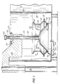
- FIG. 1 is a cross-sectional view of a preferred treatment vessel or basket and treatment medium compartment in accordance with the teachings of the present invention;
- FIG. 2 is an exploded view of a liquid exit flange for the basket of FIG. 1;
- FIG. 3 is an an exploded view of the liquid entry ports located at the bottom of the basket;
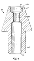
- FIG. 4 is a cross-sectional view of a ball pen point which is nickel plated in accordance with the process of the invention;
- FIG. 5 is a top view of an apparatus for sequentially carrying out a plurality of treatment methods with the basket of FIG. 1; and
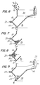
- FIGS. 6-9 illustrate the movement of the parts in the basket of FIGS. 1 or 3 during the treatment process.
- The invention resolves the problems associated with prior art methods and devices by exposing a heap or other randomly oriented aggregate of small parts and the treatment medium alternately to gravity and to centrifugal forces. This alternation is repeated as often as required and the duration and rotational speeds of these two different phases may be chosen in any required relative proportion in order to reorient and reposition the parts so that all surfaces can be uniformly treated.
- As illustrated in FIG. 1, the aggregate of parts is contained in a
basket 10 having a circular or ring shaped inclined (i.e., V-shaped) bottom surface 12 formed between anouter element 14 and aninner element 16, asidewall 38 including a circular or ring-shaped plate or baffle 18 for restricting the peripheral and upward movement of the parts when subjected to centrifugal force, a plurality ofsmall outlets 20 on the periphery of the sidewall at a maximum diameter of the vessel and an inlet or a plurality ofinlets 22 for allowing new liquid to enter the basket situated on a smaller diameter than the outlets. Thisbasket 10 rotates withvertical rod 24, by the action ofcable 26 onpulley 28 attached tocylindrical tube 30. Thebasket 10 is attached totube 30 by weldingspider plates 36 to an upper portion of thesidewall 38. A suitable number of spider plates, such as three, for example, is used to provide sufficient support for thebasket 10.Basket 10 is also provided with an open top bounded byperipheral lip 40. - As shown, the
basket 10 is preferably immersed beneath the normaloperational level 32 of theliquid treatment medium 34. For the situation when the treatment medium is a fluid, such fluid can enter the basket through theinlets 22 or over the top of thelip 40 of thebasket 10 and through openings between thespider plates 38. For the duration of the rotating phase of the basket, liquid which is removed from the basket by centrifugal force through thesmall outlets 20 is constantly replenished by liquid entering the basket throughinlets 22 and by flowing overlip 40. -
Basket 10 is operatively associated with means for rotation, illustratively shown bybelt 26 andpulley 28. The driving means (not shown) can include any conventional motor having variable speed and directional controls so that clockwise or counterclockwise rotation of the basket at different speeds and accelerations or declelerations can be achieved. - The
inner element 16 of the V-shaped bottom surface 12 is securely attached tovertical rod 24, which is provided withhead 42.Spring 44 exerts sufficient force between the upper end oftube 30 andhead 42 to maintain contact of the outer surface ofinner element 16 with the lower edge of bottom surfaceouter element 14, thus forming small fluidmedium inlets 22 capable of retaining the parts in thebasket 10 for processing. When the parts are to be removed from the basket, a force is applied to head 42 sufficient to overcome the force ofspring 44, thereby separating the inner and outer elements of the V-shaped bottom surface 12 so that parts can pass between the elements. This feature is shown in more detail in FIG. 8, wherein the downward movement ofrod 24 is evidenced by increaseddistance 43 between the attachment point of inner element 15 torod 24 and the lower end oftube 30. - Means for vertically positioning the
basket 10 is also provided, preferably in the form of alift arm 46 which is raised or lowered byjack 48. Thisjack 48 which may be electrically, pneumatically or hydraulically operated, can position thebasket 10 fully beneath thenormal liquid level 32 of thetreatment medium 34, partially beneath such liquid level, or when treatment is completed, above the liquid level so that all treatment fluid can be removed from thebasket 10. In addition to the removal of liquid due to gravitational forces, thebasket 10 can be rotated to utilize centrifugal force to assist in the removal of liquid from between the parts and out of thebasket 10. - The treatment medium is retained within
tank 50, which has sidewalls sufficiently high to allowbasket 10 to be rotated above theliquid level 32 for removal of liquid therefrom without throwing fluid outside oftank 50. Thus, liquid being removed from theoutlets 20 of thebasket 10 when it is rotated above theliquid level 32 splashes against the inside of thetank 50 sidewalls, where it drops back into the liquid 34 below. In order to be able to rotate thebasket 10 in any of these vertical positions, the drive means for thecable 26 andpulley 28 may be mounted onarm 46. Finally,arm 46 is capable of movement to a position above that of thetank 50 sidewalls for transmittal of the basket to a second treatment medium holding vessel. This is accomplished by raisingarm 46 to the proper height to removebasket 10 fromvessel 50. - FIG. 2 illustrates the
liquid outlets 20 which are formed at the largest inner diameter of the basket. Theseoutlets 20 are rectangular shallow grooves cut inflange 52 attached to and forming part ofbottom surface 14.Flange 52 mates withflange 54 which extends fromsidewall 18. Theseflanges grooves 20 are controlled in order to obtain the proper rate of liquid exitingbasket 10 while retaining the parts therein. - The
rotatable basket 10 has a shape which, in conjunction with centrifugal force induced by suitable rotational speeds, moves the parts from a lower resting position, where they form a ring shaped aggregate in the V-shaped bottom 12 ofvessel 10, to a higher position where they form a ring-shaped mass having a diameter as large as the largest internal dimension of the basket permits. Theoutlets 20 are placed at this largest dimension, which is bound by the bottom surfaceouter element 14 andsidewall 18. The coefficient of friction determines, in part, the degree of centrifugal force necessary to move and expand all parts to the higher position. After the parts or objects to be treated reach this position, the speed of the basket could be reduced just enough to maintain the ring-shaped mass at such maximum periphery. The speed is preferably controlled sufficiently to allow the treatment medium to flow into, around, through and out of the parts. Also, speed control can be used to allow the parts to circulate to expose and orient all surfaces relative to the treatment medium. - When the speed is reduced, the parts slide back into the aggregate shape, thereby further changing their individual positions so that when they again are subjected to the centrifugal force, their surfaces or other features will have taken a different position and orientation. If the basket has its rotation determined by a controlled speed system, any required degree of gentleness or vigorousness of movement can be achieved, and rotation could be counterclockwise, clockwise or oscillating, as desired. A change of direction of rotation (e.g. from clockwise to counterclockwise) also assists in the repositioning and reorienting of the part surfaces.
- The best mode of the invention relates to the electroless plating of a plurality of ball pen points with a deposit of nickel. As such, the treatment medium is an electroless nickel plating bath preceded and succeeded by preparatory and subsequent treatment baths. No particular criticality is attributed to the specific composition of this bath: any conventional electroless nickel electrolyte would be suitable for use in the process of this invention.
- When a plurality of ball pen writing points, such as the one illustrated as 60 in FIG. 4, are plated with electroless nickel in accordance with this invention, it is possible to obtain a uniform deposit of 2 to 3 micrometers in the critical areas such as the
ball socket 62 and theball retaining lip 62 andrim 64, as outlined by the dotted line, while all other surfaces, such as theshank 66, connectinghole 68 andcapillary hole 69, which surfaces are to be protected from contact with the ink, will be provided with a coating having a thickness in the range of 1 to 1.5 micrometers. The general construction of such pen points is well known in the art, but it was heretofore not possible to achieve such uniform dimensions of the coatings thereupon, which coatings are intended to increase the corrosion and/or wear resistance of the points. Since the writing quality of the pen depends upon the precision and geometry of the machining of the points, the deposit of a non-unifrom coating upon such points would defeat the objective of such precision machining, which can be accomplished at a tolerance level of ± 1.5 micrometers. - Verification of the exact thickness of the electroless plating can be obtained by X-ray fluorescence measurement with methods such as 3-D topological surface mapping. A 0.1 mm spot size would be suitable for such measurements on writing points. An acceptable instrument for carrying out these measurements is available from Veeco Instruments, Inc., Syosset, New York, as Model XRF300.
- Referring again to FIG. 1, the
treatment medium 34 could be an electroless nickel plating solution, which can enter thebasket 10 throughopenings 22 inbottom surface 14. Theseopenings 22 are formed by grooves cut in the bottom ofplate 14 at the point whereplate 14 meetsplate 16. Thebasket 10 and all materials that come in contact with electroless nickel bath are formed from polypropylene or other suitably resistant material. If desired, aromatic polyester liquid crystal polymers, such as Dupont HX-2000, 3000 or 4000 series Thermoplastic Polyester Resins can be used for the basket when higher temperature treatment mediums are contemplated. - If desired, although not necessary for this embodiment, a
sparge pipe 56 can be used to direct a stream of properly mixed and agitated plating solution towardinlets 22. This solution is recirculated from the treatmentmedium holding vessel 50 throughpipe 58, by way ofpump 59 positioned inpipe 58 which leads tosparger 56. Alternatively, a plurality of spargers arranged in a row or circular configuration or a single ring-shaped sparger can be used for directing the plating solution at thebasket 10 when the basket is not rotated. Also, for the embodiment shown,basket 10 is rotated in either a clockwise or counterclockwise direction, or can be oscillated, to assist in contacting the entire aggregate of parts with the solution. - It would be advantageous to utilize a continuous process for sequentially subjecting the parts to different treatments. For example, in the electroless nickel plating of parts, it may be desirable to initially degrease the parts by immersion in a solvent, followed by a rinse whereby all solvent is removed, prior to immersing the parts in the electrolyte. Thereafter, a rinse is used to remove remaining electrolyte from the plated parts, followed by a drying operation as a final treatment to the rinsed parts.
- It is possible to utilize a
single vessel 50 into which the various solutions can be introduced and removed. These solutions are held in various storage tanks which are connected tovessel 50 by the appropriate piping, valving and pumping arrangements. Thevessel 50 is initially filled. with a first treatment medium and thebasket 10 is lowered into the medium for treatment of the parts. After competion of the first treatment, it is possible to remove substantially all of the liquid entrained between, around or inside the parts by rotating the basket while the basket is raised above thenormal liquid level 32 of the treatment medium, but within the walls of thevessel 50, so that the resulting centrifugal force drives the treatment medium out from the basket and its contents and back into the liquid 34. Then, the treatment medium is removed from thevessel 50, by draining or pumping, while the basket remains in the raised position. A subsequent medium is then introduced into the vessel, again preferably by pumping, and the sequence is repeated. This can be done as often as necessary for the desired number of treatments. - For larger production volumes, such multiple, sequential treatments can also be carried out by providing the
mechanism 48 for raising and lowering the basket in combination with a rotatable carousel 70, as shown in FIG. 5. This enables multiple baskets to be used simultaneously in combination with the separate treatment mediums. The carousel 70 generally has a plurality ofcompartments - While the basket or baskets are raised, the treatment medium can be removed as noted above. The walls of the compartments are sufficiently high to prevent mixing of the treatment mediums when the basket is rotated to remove same. The basket or baskets are then introduced into the subsequent compartments for treatment by repeating the earlier described cycle of alternately exposing the parts to the forces of gravity and to centrifugal forces as in the previous compartment.
- As illustrated in FIG. 5, carousel 70 can retain, e.g., six different treatment mediums in its compartments. A typical process would include a degreasing solvent in
compartment 72, a solvent rinse in 74, a water rinse in 76, an electroless nickel plating solution in 78, another water rinse in 80 and heated air recirculation chamber in 82 to dry the plated parts. FIG. 5 shows the parts inbasket 10 in the electroless nickel plating solution ofcompartment 78, with the water rinse 80 and dryingtreatment 82 remaining before the cycle will be completed. - As noted above, the basket can be rotated after being lifted above the liquid level to remove remaining liquid from the parts. The compartment walls should extend sufficiently above the normal liquid level of the treatment fluid to prevent liquid which is driven out where the basket is rotated to contaminate adjacent compartments.
- Other arrangements can be used to achieve sequential treatments of the parts. Although not preferred, it is possible to arrange for the basket to be moved along a path of travel between adjacent vessels which contain different treating solutions. This embodiment can also utilize multiple baskets for increased production rates.
- FIGS. 6-9 illustrate the loading, unloading, and movement of the heap of small parts during the treatment cycle referred to above. Initially, as shown in FIG. 6, the parts are introduced into the basket preferably before the basket is immersed into the treatment medium. The rotation of the basket is oscillated to distribute these parts evenly so that they occupy the V-shaped bottom of the basket as shown in FIG. 7. When the basket is thereafter rotated to the appropriate speed, the ring-shaped aggregate of parts is raised and expanded to the area bounded by the outer portion of the bottom 14 and
sidewall 18 ofbasket 10. As the basket continues to rotate, the treatment medium passes into, around, through, and out from the parts and then exits the vessel throughopenings 20, as illustrated in FIG. 8. - During operation of the basket as shown in FIGS. 7 and 8, a stream of treating medium may be directed toward the
inlets 22. After the parts have received their treatments and the rotation of the basket is terminated, the parts return to their initial ring-shaped configuration in the lowest portion of V-shaped bottom. At that time, the parts can be removed from the basket by separating the V-shaped bottom surface at the point of the V. - In FIG. 1, the
upper portion 18 of thebasket 10 is attached totube 30 by means ofspider plates 36. The openings between these plates allow the introduction of the parts into the vessel. Thebottom wall 16 is connected to arod 24 which is movable axially relative totube 30. Thus, the unloading of the parts shown in FIG. 8 is carried out by separatingplate 16 fromplate 14. The separation of inner and outer elements is described above. - As is evident from the other portions of the present specification, the phase of treatment shown in FIG. 6 is carried out before the basket is introduced into the treatment medium. The phase of treatment shown in FIG. 9 is carried out after lifting the basket above the medium 34 of the last treatment compartment, carefully spinning off the treatment medium and placing a catch pan underneath the basket but before the parts are removed therefrom.
- To move the parts to the upper position shown in FIG. 8, a rotational speed sufficient to overcome that of gravity and the coefficient of friction is required. As soon as the parts attain the ring-shaped mass configuration, the rotational speed can be reduced. A preferred diameter for the basket is about 500 mm at the maximum inner diameter and 450 mm at the lower position of the parts. Also,
grooves 20 preferably have a depth of 0.5 mm and a width of 3 mm, their length being the same as the width offlange 52. If desired, thegrooves 20 can be of any angular orientation with respect to the flange to achieve the desired flow rate of the treatment medium exiting the vessel. - This forced flow method can be useful for cleaning, electroplating, depositing, sublimating, insulating, hardening, wetting, making repellant, etching, making conductive, reactive, making inert, or to produce any reaction that can be achieved through the interaction of liquids, solids or gases upon the surfaces of small parts which are treated in a batch, heap or aggregate.
Claims (12)
- An apparatus for the uniform treatment, e.g. wetting or drying, of the surfaces of a plurality of individual parts when such parts constitute a randomly oriented aggregate, comprising
a basket (10) for holding said aggregate of parts to be treated,
means (26) for rotating said basket (10) about an axis with at least two different rotational speeds,
an inclined bottom surface (12) and a sidewall (18),
outlet means (20) in said sidewall (18) to allow exit of a treatment fluid (34),
caracterized in that:
said bottom surface (12) being formed between an outer element (14), inclined upwards and outwards and an inner element (16), inclined downwards and outwards relative said axis. - The apparatous according to claim 1, further characterized in that the outermost part of said outer element (14) is adjacent to a portion of said sidewall (18) which is inclined upwards and inwards relative said axis, said outer element (14) and said portion meet at the maximum diameter of said basket (10).
- The apparatous according to claim 1 or 2, further characterized in that said outlet means (20) are located at said maximum diameter of said basket (10).
- The apparatus according to one of the preceeding claims, further characterized in that said sidewall (18) together with said outer element (14) is vertically movable in relation to said inner element (16), thereby providing annular opening means at the lowermost part of said bottom surface (12) for the removing of said parts.
- The apparatous according to one of the preceeding claims, further characterized in that each of said inner element (16), said outer element (14) and said portion of said side wall (18) are substantially free from other openings.
- The apparatous according to claim 4, further characterized in that the lower edge of said outer element (14) together with said inner element (16) define treatment fluid inlet means at the lowermost part of said bottom (12).
- A method for the uniform treatment, e.g. wetting or drying, of the surfaces of a plurality of individual parts when such parts constitute a randomly oriented aggregate, comprising at least the following steps:a) introducing a plurality of parts into a basket (10) with an inclined bottom to form said aggregate;b) introducing said basket (10) into a treatment medium (34) so that said treatment medium enters into said basket;c) rotating said basket at controlled speed in order to bring said treatment medium into contact with the surface of said parts;d) removing said treatment medium from said basket;e) rotating said basket at controlled speed generally different from the speed of step c) in order to remove essentially all of said treatment medium (34) from the parts by the centrifugal forces;f) removing said parts from said basket;characterized:
in that said basket (10) includes a bottom surface (12) which is at least partially inclined outwards and upwards relative the axis of rotation;
in that at least one of steps c) and e) respectively consists of repeatedly separating and dispersing said parts from said aggregate and then returning said parts back into said aggregate during controlled cycles by repeatedly changing the rotational speed of said basket (10) from a first value to a second value and back to said first value;
in that said first value of rotational speed allows said parts to climb in an outwardly direction along said inclined surface (12) due to the centrifugal forces and
in that said second value of rotational speed allows said parts to fall in an inwardly direction along said inclined surface (12) due to the force of gravity. - A method for the uniform drying of the surfaces of a plurality of individual parts when such parts constitute a randomly oriented aggregate, comprising at least the following steps:a) introducing a plurality of wet parts into a basket (10) with an inclined bottom to form said agregate;b) rotating said basket at controlled speed in order to remove essentially all of the liquid medium from said parts by the centrifugal forces;c) removing said dryed parts from said basket;characterized:
in that said basket (10) includes a bottom surface (12) which is at least partially inclined outwards and upwards relative the axis of rotation;
in that step b) consists of repeatedly separating and dispersing said parts from said aggregate and then returning said parts back into said aggregate during controlled cycles by repeatedly changing the rotational speed of said basket (10) from a first value to a second value;
in that the first value of rotational speed allows said parts to climb in an outwardly direction along said inclined surface (12) due to the centrifugal forces and
in that said second value of rotational speed allows said parts to fall in an inwardly direction along said inclined surface (12) due to the force of gravity. - The method according to any of the claims 7 or 8, further characterized
in that the sidewall (18) of the basket (10) has a diameter which is the baskets largest width and
in that the first value of rotational speed allows said parts to climb up to said largest width. - The method according to any of the claims 7 to 9, further characterized
in that the second value of speed allows said parts to slide back to the lowermost position along said inclined surface (12) due to the force of gravity. - The method according to any of the claims 7 to 10, further characterized in that said parts are ball pen writing points (60).
- A method for the uniform treatment, e.g. wetting or drying, of the surfaces of a plurality of individual parts when such parts constitute a randomly oriented aggregate contained in a rotatable basket (10) with an inclined bottom surface and a sidewall,
characterized in that:
said bottom surface (12) is at least partially inclined outwards and upwards relative the axis of rotation;
said sidewall (18) has a diameter which is the baskets largest width;
the rotation velocity of said basket is elevated in a gentle manner in order to avoid all deleteriously affects and thereby forcing said parts to climb outwards and upwards along said inclined surface (12) until they come to rest at said largest width of said basket where they remain without further movement relative one another and the basket,
the rotation velocity is further elevated and kept on a high level for a predetermined time period in order either to remove all traces of fluid from the surface of said parts, out of the narrow passages between said parts and out of blind holes of said parts,
or to force fluid through the narrow passages between said parts,
the rotation velocity is reduced until the force of gravity brings said parts along said inclined bottom surface (12) downwards and inwards to the lowermost part of the inclined bottom of said basket,
this process being repeated several times in order to asure positioning and orienting of all surfaces of all parts in the desired way.
Applications Claiming Priority (2)
| Application Number | Priority Date | Filing Date | Title |
|---|---|---|---|
| US07/340,881 US4938840A (en) | 1989-04-19 | 1989-04-19 | Uniform treatment of large quantities of small parts |
| US340881 | 2003-01-09 |
Publications (2)
| Publication Number | Publication Date |
|---|---|
| EP0394212A1 EP0394212A1 (en) | 1990-10-24 |
| EP0394212B1 true EP0394212B1 (en) | 1995-01-18 |
Family
ID=23335326
Family Applications (1)
| Application Number | Title | Priority Date | Filing Date |
|---|---|---|---|
| EP90890093A Expired - Lifetime EP0394212B1 (en) | 1989-04-19 | 1990-03-30 | Apparatus and process for the uniform treatment of large quantities of small parts |
Country Status (3)
| Country | Link |
|---|---|
| US (1) | US4938840A (en) |
| EP (1) | EP0394212B1 (en) |
| DE (1) | DE69016083T2 (en) |
Cited By (1)
| Publication number | Priority date | Publication date | Assignee | Title |
|---|---|---|---|---|
| CN110479688A (en) * | 2019-08-05 | 2019-11-22 | 马鞍山致青工业设计有限公司 | A rotary pickling device for recycling pickling liquid used in silicon wafer production |
Families Citing this family (8)
| Publication number | Priority date | Publication date | Assignee | Title |
|---|---|---|---|---|
| US5236134A (en) * | 1991-11-05 | 1993-08-17 | Envirocycle Incorporated | Method of reclaiming glass from articles formed of leaded glass |
| GB2321864B (en) * | 1997-02-11 | 2001-05-30 | Protective Finishing Group Ltd | Apparatus and method for removing excess liquid from articles |
| ES2171124B1 (en) * | 2000-08-04 | 2003-11-16 | Hlt Gmbh | PROCEDURE FOR THE PREPARATION OF ORGANIC OR INORGANIC SAMPLES FOR YOUR CLINICAL OR SCIENTIFIC EXAMINATION AND MACHINE TO PERFORM SUCH PROCEDURE. |
| US20020197492A1 (en) * | 2001-06-25 | 2002-12-26 | Ling Hao | Selective plating on plastic components |
| DE102007002774B4 (en) * | 2007-01-18 | 2009-01-15 | Ralf Ott | cleaner |
| DE102010060995A1 (en) | 2010-12-03 | 2012-06-06 | Rnb-Ott Ug | Cleaning apparatus for cleaning metal component e.g. screw, has coupling device that is set for coupling flushing device with cleaning machine |
| WO2021119812A1 (en) * | 2019-12-17 | 2021-06-24 | Covalon Technologies Ltd. | Reactors for coating devices and related systems and methods |
| US12331169B2 (en) * | 2020-05-28 | 2025-06-17 | Cargill, Incorporated | Preparing a blend of polysaccharide and ingredient |
Family Cites Families (10)
| Publication number | Priority date | Publication date | Assignee | Title |
|---|---|---|---|---|
| US3035959A (en) * | 1958-04-10 | 1962-05-22 | Clevite Corp | Sorting and etching apparatus and method |
| US3031363A (en) * | 1959-09-24 | 1962-04-24 | Sylvania Electric Prod | Method and apparatus for treating bodies of semiconductor material |
| BE791832A (en) * | 1971-11-26 | 1973-03-16 | Degussa | PROCESS FOR THE TREATMENT OF PARTS IN LIQUIDS, IN PARTICULAR FOR DENTAL TECHNOLOGY, AND DEVICE THEREFORE |
| US3891456A (en) * | 1973-10-17 | 1975-06-24 | Us Air Force | Surface treatment of titanium and titanium alloys |
| DE2748615C2 (en) * | 1977-10-29 | 1987-01-08 | Richard 5202 Hennef Steimel | Process for deoiling, tumbling, washing and drying, in particular of objects with blind holes, and centrifuge for carrying out the process |
| CH652322A5 (en) * | 1982-12-28 | 1985-11-15 | Le Clou S A | Machine for using flammable solvents for washing objects, especially parts covered with paint spray |
| GB2134431B (en) * | 1983-02-04 | 1986-05-21 | Atomic Energy Authority Uk | Improvements in ball-point pens |
| FR2569427B1 (en) * | 1984-08-23 | 1986-11-14 | Commissariat Energie Atomique | METHOD AND DEVICE FOR DEPOSITING ONTO A SUBSTRATE OF A THIN FILM OF A COMPOUND COMPRISING AT LEAST ONE CATIONIC COMPONENT AND AT LEAST ONE ANIONIC CONSTITUENT |
| US4563239A (en) * | 1984-10-16 | 1986-01-07 | United Technologies Corporation | Chemical milling using an inert particulate and moving vessel |
| US4830638A (en) * | 1986-06-16 | 1989-05-16 | Priestley Jr Joseph B | Filtration system with apparatus for altering the arrangement of electrons in particles |
-
1989
- 1989-04-19 US US07/340,881 patent/US4938840A/en not_active Expired - Lifetime
-
1990
- 1990-03-30 EP EP90890093A patent/EP0394212B1/en not_active Expired - Lifetime
- 1990-03-30 DE DE69016083T patent/DE69016083T2/en not_active Expired - Lifetime
Cited By (2)
| Publication number | Priority date | Publication date | Assignee | Title |
|---|---|---|---|---|
| CN110479688A (en) * | 2019-08-05 | 2019-11-22 | 马鞍山致青工业设计有限公司 | A rotary pickling device for recycling pickling liquid used in silicon wafer production |
| CN110479688B (en) * | 2019-08-05 | 2022-02-11 | 马鞍山致青工业设计有限公司 | A rotary pickling device for recycling pickling solution for silicon wafer production |
Also Published As
| Publication number | Publication date |
|---|---|
| DE69016083T2 (en) | 1995-06-22 |
| US4938840A (en) | 1990-07-03 |
| EP0394212A1 (en) | 1990-10-24 |
| DE69016083D1 (en) | 1995-03-02 |
Similar Documents
| Publication | Publication Date | Title |
|---|---|---|
| US7147765B2 (en) | Apparatus and method for deposition of an electrophoretic emulsion | |
| KR940003373B1 (en) | Apparatus for processing a surface of a substrate | |
| KR0167572B1 (en) | Apparatus of coating wafer | |
| KR100654698B1 (en) | Method and Apparatus for Processing Substrate | |
| US4938840A (en) | Uniform treatment of large quantities of small parts | |
| JP3126867B2 (en) | Plating apparatus and plating method for small items | |
| US4286541A (en) | Applying photoresist onto silicon wafers | |
| US7390383B2 (en) | Paddles and enclosures for enhancing mass transfer during processing of microfeature workpieces | |
| US5865894A (en) | Megasonic plating system | |
| US20050121313A1 (en) | Method and apparatus for executing plural processes on a microelectronic workpiece at a single processing station | |
| EP0089454A1 (en) | Liquid treatment apparatus and method | |
| WO2003057943A2 (en) | Electroless plating system | |
| KR100824759B1 (en) | Substrate Processing Equipment and Substrate Plating Equipment | |
| KR20060024792A (en) | Methods and Systems for Processing Microfeature Workpieces with Flow Agitators and / or Multiple Electrodes | |
| US7090750B2 (en) | Plating | |
| US4068251A (en) | Developing device for printing plates | |
| US3699918A (en) | Galvanizing apparatus | |
| KR100710805B1 (en) | Substrate cleaning apparatus and method used for semiconductor device manufacturing | |
| RU2846198C1 (en) | Device for forming thin-film coatings of nano-sized thickness by ion deposition | |
| RU2841707C1 (en) | Device for forming thin-film coatings of nano-sized thickness by ion deposition | |
| JPS6327784Y2 (en) | ||
| RU2841734C1 (en) | Device for forming thin-film coatings of nano-sized thickness by ion deposition | |
| RU2841649C1 (en) | Device for forming thin-film coatings of nano-sized thickness by ion deposition | |
| JPH10163161A (en) | Spin processing device | |
| JP2001262392A (en) | Megasonic plating by dipping type array |
Legal Events
| Date | Code | Title | Description |
|---|---|---|---|
| PUAI | Public reference made under article 153(3) epc to a published international application that has entered the european phase |
Free format text: ORIGINAL CODE: 0009012 |
|
| AK | Designated contracting states |
Kind code of ref document: A1 Designated state(s): CH DE FR GB LI |
|
| 17P | Request for examination filed |
Effective date: 19901115 |
|
| 17Q | First examination report despatched |
Effective date: 19920713 |
|
| RAP1 | Party data changed (applicant data changed or rights of an application transferred) |
Owner name: BIC |
|
| GRAA | (expected) grant |
Free format text: ORIGINAL CODE: 0009210 |
|
| AK | Designated contracting states |
Kind code of ref document: B1 Designated state(s): CH DE FR GB LI |
|
| REF | Corresponds to: |
Ref document number: 69016083 Country of ref document: DE Date of ref document: 19950302 |
|
| ET | Fr: translation filed | ||
| PLBE | No opposition filed within time limit |
Free format text: ORIGINAL CODE: 0009261 |
|
| STAA | Information on the status of an ep patent application or granted ep patent |
Free format text: STATUS: NO OPPOSITION FILED WITHIN TIME LIMIT |
|
| 26N | No opposition filed | ||
| REG | Reference to a national code |
Ref country code: GB Ref legal event code: IF02 |
|
| PGFP | Annual fee paid to national office [announced via postgrant information from national office to epo] |
Ref country code: CH Payment date: 20040312 Year of fee payment: 15 |
|
| PG25 | Lapsed in a contracting state [announced via postgrant information from national office to epo] |
Ref country code: CH Free format text: LAPSE BECAUSE OF NON-PAYMENT OF DUE FEES Effective date: 20050331 Ref country code: LI Free format text: LAPSE BECAUSE OF NON-PAYMENT OF DUE FEES Effective date: 20050331 |
|
| REG | Reference to a national code |
Ref country code: CH Ref legal event code: PL |
|
| PGFP | Annual fee paid to national office [announced via postgrant information from national office to epo] |
Ref country code: DE Payment date: 20090327 Year of fee payment: 20 |
|
| PGFP | Annual fee paid to national office [announced via postgrant information from national office to epo] |
Ref country code: FR Payment date: 20090317 Year of fee payment: 20 |
|
| PGFP | Annual fee paid to national office [announced via postgrant information from national office to epo] |
Ref country code: GB Payment date: 20090403 Year of fee payment: 20 |
|
| REG | Reference to a national code |
Ref country code: GB Ref legal event code: PE20 Expiry date: 20100329 |
|
| PG25 | Lapsed in a contracting state [announced via postgrant information from national office to epo] |
Ref country code: GB Free format text: LAPSE BECAUSE OF EXPIRATION OF PROTECTION Effective date: 20100329 |
|
| PG25 | Lapsed in a contracting state [announced via postgrant information from national office to epo] |
Ref country code: DE Free format text: LAPSE BECAUSE OF EXPIRATION OF PROTECTION Effective date: 20100330 |