EP0394208B1 - Schutzvorrichtung für Silageschneider - Google Patents
Schutzvorrichtung für Silageschneider Download PDFInfo
- Publication number
- EP0394208B1 EP0394208B1 EP90850141A EP90850141A EP0394208B1 EP 0394208 B1 EP0394208 B1 EP 0394208B1 EP 90850141 A EP90850141 A EP 90850141A EP 90850141 A EP90850141 A EP 90850141A EP 0394208 B1 EP0394208 B1 EP 0394208B1
- Authority
- EP
- European Patent Office
- Prior art keywords
- front part
- grab
- silage
- protective device
- rear frame
- Prior art date
- Legal status (The legal status is an assumption and is not a legal conclusion. Google has not performed a legal analysis and makes no representation as to the accuracy of the status listed.)
- Expired - Lifetime
Links
- 239000004460 silage Substances 0.000 title claims abstract description 41
- 230000001681 protective effect Effects 0.000 title claims abstract description 36
- 239000000725 suspension Substances 0.000 claims 1
- 241001465754 Metazoa Species 0.000 description 4
- 208000014674 injury Diseases 0.000 description 2
- 208000012260 Accidental injury Diseases 0.000 description 1
- 208000027418 Wounds and injury Diseases 0.000 description 1
- 238000010276 construction Methods 0.000 description 1
- 230000006378 damage Effects 0.000 description 1
- 238000000151 deposition Methods 0.000 description 1
- 239000012530 fluid Substances 0.000 description 1
- 230000000266 injurious effect Effects 0.000 description 1
- 238000012986 modification Methods 0.000 description 1
- 230000004048 modification Effects 0.000 description 1
Images

Classifications
-
- A—HUMAN NECESSITIES
- A01—AGRICULTURE; FORESTRY; ANIMAL HUSBANDRY; HUNTING; TRAPPING; FISHING
- A01F—PROCESSING OF HARVESTED PRODUCE; HAY OR STRAW PRESSES; DEVICES FOR STORING AGRICULTURAL OR HORTICULTURAL PRODUCE
- A01F25/00—Storing agricultural or horticultural produce; Hanging-up harvested fruit
- A01F25/16—Arrangements in forage silos
- A01F25/20—Unloading arrangements
- A01F25/2027—Unloading arrangements for trench silos
- A01F2025/2054—Machinery for cutting successive parallel layers of material in a trench silo
-
- A—HUMAN NECESSITIES
- A01—AGRICULTURE; FORESTRY; ANIMAL HUSBANDRY; HUNTING; TRAPPING; FISHING
- A01F—PROCESSING OF HARVESTED PRODUCE; HAY OR STRAW PRESSES; DEVICES FOR STORING AGRICULTURAL OR HORTICULTURAL PRODUCE
- A01F25/00—Storing agricultural or horticultural produce; Hanging-up harvested fruit
- A01F25/16—Arrangements in forage silos
- A01F25/20—Unloading arrangements
- A01F25/2027—Unloading arrangements for trench silos
- A01F2025/2072—Scoops with an extracting tool mounted inside or in the vicinity of said scoop
Definitions
- This invention relates to a protective device for silage grabs of the kind comprising a rear frame part having attachment means for fitting the grab to a carrier vehicle, and a front part which is pivotally arranged in relation to the rear frame part, the front part comprising at least one cutting edge, and which grab further comprises means for bringing about the pivoting movement of the front part in relation to the rear frame part.
- silage grabs by means of which, for instance, a square section block of silage can be cut out from silage or fodder clamps, and transported to the intended delivery site while held by the grab, which is normally carried on an agricultural tractor.
- the object of the present invention is to provide such silage grabs with a higly simple, but nevertheless effective protective device, or guard, which will shield the cutting edge of the grab from unintentional contact with people and animals present in the vicinity thereof to the greatest possible extent, and therewith guard against accidental injury to both humans and animals.
- a protective device having the characteristic features set forth in the following claims.
- the inventive device is thus effective in preventing people and animals from coming into accidental contact with the cutting edge or edges with which silage is cut from the silo or fodder clamp.
- This safety measure is essential when, for instance, feeding animals, which in their eagerness to reach the food are likely to come into contact with the cutting edge(s) and inflict serious injury upon themselves.
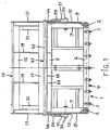
- Fig. 1 shows a front view of a silage grab equipped with the protective device according to the invention, the grab being shown in an open position;
- Fig. 2 shows a side view of a first embodiment of the silage grab;
- Fig. 3 shows a side view of the silage grab of Fig. 2 at the moment of cutting silage from a fodder store, e.g. a silage clamp;
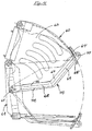
- Fig. 4 shows a side view of a second embodiment of the silage grab.
- the silage grab is intended for connection to a front loader of an agricultural tractor or to a loading machine and includes a rear frame part 1 which comprises a plurality of essentially horizontal rods or tines 2, 3 which together form the floor of the grab.
- the rear frame section 1 also includes a body structure 4 which comprises, inter alia, a top rail 5, a bottom rail 6 and two side rails 7, these rails and an number of bracing struts being welded together to form the body structure 4.
- the body structure also includes two side plates 8 and attachments (not shown) for enabling the grab to be connected to the front loader of a tractor or to a loading machine for instance.
- the tines 2 are attached to the bottom rail 6.
- the silage grab also includes a pivotally mounted front part 10 which comprises, inter alia, two side walls 11 and a cross bar 12, which connects the side walls together.
- a pivotally mounted front part 10 which comprises, inter alia, two side walls 11 and a cross bar 12, which connects the side walls together.
- a further plate 17 with a further cutting edge 18 is mounted between the side walls 11 adjacent the lower front edges thereof.
- Mounted between the cross-bar 12 and the further plate 17 are two support forks 19, the free ends 20 of which preferably extend slightly below the front cutting edge 18 on the front part 10.
- the front part 10 is journalled for pivotal movement in relation to the rear frame part 1 via two bearings 30, as shown in the figures.
- Two double-acting piston-cylinder devices operated by a pressurised medium, for instance hydraulic rams 31, are arranged to act between the rear frame part 1 and the front part 10 in a manner to allow the front part to be swung/maneuvered between an upper open position, shown in full lines in Fig. 2, and a lower closed position, indicated in chain lines in Fig. 2.
- the silage is cut from the clamp, as the front part 10 swings between the open and closed positions. Hydraulic fluid is supplied to the hydraulic rams 31 from, for instance, the hydraulic system of the tractor.
- the grab is fitted with a protective device, which has the form of a protective arcuate guard 41 which is mounted on two bearings 42 for pivotal movement in relation to the side walls 11 of the front part 10.
- the arcuate guard has a front part in the form of a tube 43 and two side parts in the form of respective curved arms 44, one end of each of which is connected to the tube 43 and the other end of each of which carries the bearing 42.
- the arms 44 are curved, so that they will conform to the positioning of the side cutting edges, to the greatest possible extent.
- the upper stop devices 50 are operative to prevent the arcuate guard from swinging upwards to such an extent as to topple over rearwardly. When no force acts on the arcuate guard 41, it rests against the lower stop devices 51 under its own weight, as illustrated in Fig. 2.
- FIG. 4 is shown there a second embodiment of the silage grab.
- This one has essentially the same construction as the silage grab according to the first embodiment shown in Fig. 2 and accordingly comprises a front part 60, which is pivotally journalled on a shaft journal 61 or the like in a rear frame part 62.
- the frame part 62 has two side walls, positioned at a distance from each other and of which only one 63 is shown in the drawing.
- the side walls 63 at their lower, front portion are connected by a plate 64, which carries a cutting edge 65 at its lower portion.
- the lower part of the side walls is provided with plates 66, 67, which are provided with a cutting edge 68, 69, respectively, and which are angled in relation to each other in similarity with the embodiment according to Fig. 2, whereby the silage can be cut out effectively from the silage clamp.
- the embodiment according to Fig. 4 is in similarity with the embodiment according to Fig. 2 provided with a protective member 70, which is pivotally journalled in relation to the front part 60 of the silage grab.
- This protective member has an arcuate form and comprises a front part 71 in the form of a tube or the like and two side arms 72, the front ends of which are fastened to the front part 71, and the rear ends of which are fastened to the rear part of the silage grab.
- the end of each 72 is pivotally journalled in the shaft 61 which projects laterally from the rear frame part 62 to a point outside each side wall 63.
- the protective device in the first-mentioned embodiment is pivotally journalled in the rear frame part 62 on the same shaft journal 62 or the like as the front part 60 of the silage grab. Due to partly that fact and partly the fact that the side arms 72 have a curvature corresponding to the angle between the cutting edges 68, 69 at the lower part of the side wall 63, so that the side arm 72 essentially follows the extension of the side cutting edges 68, 69, the protective device can give an effective protection against contact with the cutting edges not only at the front portion of the silage grab but also at the two side walls of the silage grab.
- the protective device according to Fig. 4 in similarity with the protective device according to Fig. 2 is provided with a stop means so that the protective member 70 cannot be pivoted so much in relation to the front part 60 that the protective member takes a position below the front part 60 as is apparent from Fig. 4.
- the protective device functions in the following manner: The grab is brought up to the silage clamp concerned with the grab open, i.e. with the front part 10; 60 and the protective member 41; 70 in their respective positions shown in Figs. 2, 4. The grab is then maneuvered so that the tines 2, 3 enter the silage 100, whereafter the hydraulic rams 31 are activated to swing the front part 10; 60 of the grab downwards and therewith cut a block of silage from the clamp. During this swinging movement of the front part 10; 60, the protective member 41; 70 will move out of abutment with the lower stop device and rest instead on the silage, as shown i Fig. 3. When the grab has completed its cutting action and has cut a block of silage from the clamp, i.e.
- the protective member 41; 70 will fall gravitationally onto the lower stop device therewith once more shielding the cutting edges of the grab such as to prevent contact therewith.
- the protective member 41; 70 will accompany the movement of the cutting edges 15, 16, 18; 65, 68, 69 as the front part 10; 60 is opened.
- inventive protective device can be adapted readily, for instance, to varying cutting edge configurations, so that effective protection against injurious contact with the cutting edge(s) can be provided at all times.
Landscapes
- Life Sciences & Earth Sciences (AREA)
- Environmental Sciences (AREA)
- Threshing Machine Elements (AREA)
- Storage Of Harvested Produce (AREA)
- Fodder In General (AREA)
- Storage Of Fruits Or Vegetables (AREA)
- Fittings On The Vehicle Exterior For Carrying Loads, And Devices For Holding Or Mounting Articles (AREA)
- Harvester Elements (AREA)
Claims (6)
- Schutzvorrichtung für Silagegreifer der Art, die ein hinteres Rahmenteil (1; 62) umfassen, das Befestigungsmittel zum Anbringen des Greifers an einem Trägerfahrzeug aufweist, und ein Vorderteil (10; 60) umfassen, das relativ zum hinteren Rahmenteil schwenkbar angeordnet ist, wobei das Vorderteil wenigstens eine Schneide (15, 16, 18; 65, 68, 69) umfaßt, welcher Greifer ferner Mittel (31) zum Herbeiführen der Schwenkbewegung des Vorderteils (10; 60) relativ zum hinteren Rahmenteil (1; 62) umfaßt,
dadurch gekennzeichnet,
daß die Schutzvorrichtung ein Schneidenschutzelement (41; 70) umfaßt, das relativ zum Vorderteil (10; 60) des Silagegrei- fers schwenkbar gelagert ist, und daß das Schutzelement (41; 70) ein Vorderteil (43; 71) sowie zwei Seitenarme (44; 72) umfaßt, wobei das eine Ende jedes Arms mit dem Vorderteil (43; 71) des Schutzelements verbunden ist und das andere Ende jedes Arms schwenkbar in dem Vorderteil (10; 60) des Silagegreifers gelagert ist. - Schutzvorrichtung nach Anspruch 1,
dadurch gekennzeichnet,
daß das anders Ende jedes Arms (44) an entsprechenden Seitenwänden (11) schwenkbar gelagert ist. - Schutzvorrichtung nach Anspruch 1,
dadurch gekennzeichnet,
daß das andere Ende jedes Arms (72) schwenkbar an einer Welle (30; 61) gelagert ist, die seitlich von dem hinteren Rahmenteil (1; 62) bis zu einem Punkt außerhalb jeder Seitenwand (11; 63) vorsteht, wobei die selben Wellen (30; 61) ebenfalls für die Schwenkaufhängung des Vorderteils (10; 60) des Silagegreifers verwendet werden. - Schutzvorrichtung nach Anspruch 3, wobei jede Seitenwand (63) an ihrem unteren Teil gegeneinander angewinkelte Platten (66, 67) mit einer Schneide (68, 69) aufweist,
dadurch gekennzeichnet,
daß jeder Arm (72) in einem solchen Maße gekrümmt ist, daß die Krümmung im wesentlichen dem Winkel zwischen den Platten (66, 67) mit den schneiden (68, 69) entspricht, wodurch der Seitenarm (72) im wesentlichen dem Verlauf der seitlichen Schneiden folgt und Schutz gegen einen Kontakt mit den seitlichen Schneiden des silagegreifers gibt. - Schutzvorrichtung nach einem der vorhergehenden Ansprüche,
dadurch gekennzeichnet,
daß das Vorderteil (10; 60) mit wenigstens einem, eine Begrenzung der Abwärtsschwenkbewegung des Schutzelements (41; 70) bewirkenden Anschlagmittel (51) versehen ist. - Schutzvorrichtung nach Anspruch 1 oder 2,
dadurch gekennzeichnet,
daß das Vorderteil (10) mit wenigstens einem, eine Begrenzung der Aufwärtsschwenkbewegung des Schutzelements (41) bewirkenden Anschlagmittel (50) versehen ist.
Priority Applications (1)
| Application Number | Priority Date | Filing Date | Title |
|---|---|---|---|
| AT90850141T ATE103133T1 (de) | 1989-04-19 | 1990-04-18 | Schutzvorrichtung fuer silageschneider. |
Applications Claiming Priority (2)
| Application Number | Priority Date | Filing Date | Title |
|---|---|---|---|
| SE8901415 | 1989-04-19 | ||
| SE8901415A SE463442B (sv) | 1989-04-19 | 1989-04-19 | Skyddsanordning vid foderskaerare |
Publications (2)
| Publication Number | Publication Date |
|---|---|
| EP0394208A1 EP0394208A1 (de) | 1990-10-24 |
| EP0394208B1 true EP0394208B1 (de) | 1994-03-23 |
Family
ID=20375724
Family Applications (1)
| Application Number | Title | Priority Date | Filing Date |
|---|---|---|---|
| EP90850141A Expired - Lifetime EP0394208B1 (de) | 1989-04-19 | 1990-04-18 | Schutzvorrichtung für Silageschneider |
Country Status (6)
| Country | Link |
|---|---|
| EP (1) | EP0394208B1 (de) |
| AT (1) | ATE103133T1 (de) |
| DE (1) | DE69007525T2 (de) |
| GB (1) | GB2231024B (de) |
| IE (1) | IE64113B1 (de) |
| SE (1) | SE463442B (de) |
Families Citing this family (1)
| Publication number | Priority date | Publication date | Assignee | Title |
|---|---|---|---|---|
| DE9204012U1 (de) * | 1992-03-25 | 1992-05-14 | Heide, Hans von der, 4530 Ibbenbüren | Silagegutschneidzange |
Family Cites Families (2)
| Publication number | Priority date | Publication date | Assignee | Title |
|---|---|---|---|---|
| DE2104709A1 (de) * | 1971-02-02 | 1972-08-24 | Bernhard Strautmann & Söhne, 4501 Laer | Gerät zum Entnehmen von Futterportionen aus Flach- oder Fahrsilos |
| DE2608769C2 (de) * | 1975-05-20 | 1982-06-03 | Lauri Alarik Kiuruvesi Tenhunen | Vorrichtung zum Aufschneiden, Hochheben und Transportieren eines Futtermassenstücks aus einer Futtermasse |
-
1989
- 1989-04-19 SE SE8901415A patent/SE463442B/sv not_active IP Right Cessation
- 1989-06-02 GB GB8912760A patent/GB2231024B/en not_active Expired - Fee Related
- 1989-07-03 IE IE214989A patent/IE64113B1/en not_active IP Right Cessation
-
1990
- 1990-04-18 EP EP90850141A patent/EP0394208B1/de not_active Expired - Lifetime
- 1990-04-18 AT AT90850141T patent/ATE103133T1/de not_active IP Right Cessation
- 1990-04-18 DE DE69007525T patent/DE69007525T2/de not_active Expired - Fee Related
Also Published As
| Publication number | Publication date |
|---|---|
| DE69007525T2 (de) | 1994-10-27 |
| DE69007525D1 (de) | 1994-04-28 |
| GB2231024B (en) | 1993-04-21 |
| GB8912760D0 (en) | 1989-07-19 |
| SE8901415L (sv) | 1990-10-20 |
| SE8901415D0 (sv) | 1989-04-19 |
| IE64113B1 (en) | 1995-07-12 |
| GB2231024A (en) | 1990-11-07 |
| SE463442B (sv) | 1990-11-26 |
| IE892149L (en) | 1990-10-19 |
| EP0394208A1 (de) | 1990-10-24 |
| ATE103133T1 (de) | 1994-04-15 |
Similar Documents
| Publication | Publication Date | Title |
|---|---|---|
| US4687402A (en) | Carrier for cylindrical hay bales | |
| CA1236698A (en) | Latch assembly for holding a front mounted implement in a raised position | |
| US3946887A (en) | Bale handling apparatus | |
| US4648769A (en) | Round bale handler | |
| US4930974A (en) | Extender for a tractor loader | |
| US4634336A (en) | Bale loader | |
| US7241101B2 (en) | Double action grab fork and method | |
| US4030626A (en) | Clamp for scoop loader | |
| US4302139A (en) | Material handling implement particularly suited for transporting round hay bales | |
| US4413661A (en) | Boom mount | |
| US3722724A (en) | Load carrying device with improved position control | |
| EP0083460B2 (de) | Landwirtschaftliches Gerät | |
| US4024970A (en) | Bale handling apparatus | |
| EP0394208B1 (de) | Schutzvorrichtung für Silageschneider | |
| US2181253A (en) | Traversing hoist for material and article handling | |
| EP0514314A1 (de) | Schlepperaufhängung für ein landwirtschaftliches Werkzeug, insbesondere einen Scheibenmäher oder einen Zylindermäher | |
| US3704030A (en) | Protector screen for tractor drivers | |
| US5639198A (en) | Hay bale loader | |
| US4182593A (en) | Bale loading and handling device | |
| US4746254A (en) | Material handling attachment for a tractor having a multiple-point hitch assembly including a high-lift mechanism | |
| US3208208A (en) | Automatic reel and table combination for harvesters | |
| US3080071A (en) | Bale piling attachment for traveling baler | |
| EP0674477A1 (de) | Ballenwickelvorrichtung. | |
| US2760660A (en) | Peanut stack carrier | |
| EP0127987A1 (de) | Ballen-Ladegerät |
Legal Events
| Date | Code | Title | Description |
|---|---|---|---|
| PUAI | Public reference made under article 153(3) epc to a published international application that has entered the european phase |
Free format text: ORIGINAL CODE: 0009012 |
|
| AK | Designated contracting states |
Kind code of ref document: A1 Designated state(s): AT BE CH DE DK ES FR GB IT LI LU NL SE |
|
| 17P | Request for examination filed |
Effective date: 19910416 |
|
| 17Q | First examination report despatched |
Effective date: 19920601 |
|
| GRAA | (expected) grant |
Free format text: ORIGINAL CODE: 0009210 |
|
| AK | Designated contracting states |
Kind code of ref document: B1 Designated state(s): AT BE CH DE DK ES FR GB IT LI LU NL SE |
|
| PG25 | Lapsed in a contracting state [announced via postgrant information from national office to epo] |
Ref country code: DK Effective date: 19940323 Ref country code: NL Effective date: 19940323 Ref country code: BE Effective date: 19940323 Ref country code: CH Effective date: 19940323 Ref country code: SE Free format text: THE PATENT HAS BEEN ANNULLED BY A DECISION OF A NATIONAL AUTHORITY Effective date: 19940323 Ref country code: ES Free format text: THE PATENT HAS BEEN ANNULLED BY A DECISION OF A NATIONAL AUTHORITY Effective date: 19940323 Ref country code: LI Effective date: 19940323 Ref country code: AT Effective date: 19940323 Ref country code: FR Effective date: 19940323 Ref country code: IT Free format text: LAPSE BECAUSE OF FAILURE TO SUBMIT A TRANSLATION OF THE DESCRIPTION OR TO PAY THE FEE WITHIN THE PRE;WARNING: LAPSES OF ITALIAN PATENTS WITH EFFECTIVE DATE BEFORE 2007 MAY HAVE OCCURRED AT ANY TIME BEFORE 2007. THE CORRECT EFFECTIVE DATE MAY BE DIFFERENT FROM THE ONE RECORDED.SCRIBED TIME-LIMIT Effective date: 19940323 |
|
| REF | Corresponds to: |
Ref document number: 103133 Country of ref document: AT Date of ref document: 19940415 Kind code of ref document: T |
|
| REF | Corresponds to: |
Ref document number: 69007525 Country of ref document: DE Date of ref document: 19940428 |
|
| PG25 | Lapsed in a contracting state [announced via postgrant information from national office to epo] |
Ref country code: LU Free format text: LAPSE BECAUSE OF NON-PAYMENT OF DUE FEES Effective date: 19940430 |
|
| PG25 | Lapsed in a contracting state [announced via postgrant information from national office to epo] |
Ref country code: GB Effective date: 19940623 |
|
| REG | Reference to a national code |
Ref country code: CH Ref legal event code: PL |
|
| EN | Fr: translation not filed | ||
| NLV1 | Nl: lapsed or annulled due to failure to fulfill the requirements of art. 29p and 29m of the patents act | ||
| PLBE | No opposition filed within time limit |
Free format text: ORIGINAL CODE: 0009261 |
|
| STAA | Information on the status of an ep patent application or granted ep patent |
Free format text: STATUS: NO OPPOSITION FILED WITHIN TIME LIMIT |
|
| GBPC | Gb: european patent ceased through non-payment of renewal fee |
Effective date: 19940623 |
|
| 26N | No opposition filed | ||
| PGFP | Annual fee paid to national office [announced via postgrant information from national office to epo] |
Ref country code: DE Payment date: 20050414 Year of fee payment: 16 |
|
| PG25 | Lapsed in a contracting state [announced via postgrant information from national office to epo] |
Ref country code: DE Free format text: LAPSE BECAUSE OF NON-PAYMENT OF DUE FEES Effective date: 20061101 |