EP0394108A1 - Installation for continuous and real-time measurements of metal masses in acid solution, and of the acidity of this solution - Google Patents
Installation for continuous and real-time measurements of metal masses in acid solution, and of the acidity of this solution Download PDFInfo
- Publication number
- EP0394108A1 EP0394108A1 EP90401011A EP90401011A EP0394108A1 EP 0394108 A1 EP0394108 A1 EP 0394108A1 EP 90401011 A EP90401011 A EP 90401011A EP 90401011 A EP90401011 A EP 90401011A EP 0394108 A1 EP0394108 A1 EP 0394108A1
- Authority
- EP
- European Patent Office
- Prior art keywords
- solution
- cell
- circulation
- acidity
- installation according
- Prior art date
- Legal status (The legal status is an assumption and is not a legal conclusion. Google has not performed a legal analysis and makes no representation as to the accuracy of the status listed.)
- Withdrawn
Links
- 238000005259 measurement Methods 0.000 title claims abstract description 58
- 238000009434 installation Methods 0.000 title claims abstract description 48
- 229910052751 metal Inorganic materials 0.000 title claims abstract description 26
- 239000002184 metal Substances 0.000 title claims abstract description 26
- 239000002253 acid Substances 0.000 title claims description 9
- 239000000243 solution Substances 0.000 claims abstract description 140
- 150000002739 metals Chemical class 0.000 claims abstract description 25
- 238000001514 detection method Methods 0.000 claims description 12
- 229910052695 Americium Inorganic materials 0.000 claims description 11
- GRYLNZFGIOXLOG-UHFFFAOYSA-N Nitric acid Chemical compound O[N+]([O-])=O GRYLNZFGIOXLOG-UHFFFAOYSA-N 0.000 claims description 11
- 229910052778 Plutonium Inorganic materials 0.000 claims description 11
- 229910052770 Uranium Inorganic materials 0.000 claims description 11
- LXQXZNRPTYVCNG-UHFFFAOYSA-N americium atom Chemical compound [Am] LXQXZNRPTYVCNG-UHFFFAOYSA-N 0.000 claims description 11
- 229910017604 nitric acid Inorganic materials 0.000 claims description 11
- OYEHPCDNVJXUIW-UHFFFAOYSA-N plutonium atom Chemical compound [Pu] OYEHPCDNVJXUIW-UHFFFAOYSA-N 0.000 claims description 11
- JFALSRSLKYAFGM-UHFFFAOYSA-N uranium(0) Chemical compound [U] JFALSRSLKYAFGM-UHFFFAOYSA-N 0.000 claims description 11
- 238000007599 discharging Methods 0.000 claims description 5
- 239000012088 reference solution Substances 0.000 claims description 5
- 239000003929 acidic solution Substances 0.000 abstract 1
- 230000002285 radioactive effect Effects 0.000 description 7
- 230000005855 radiation Effects 0.000 description 5
- 238000000034 method Methods 0.000 description 3
- 238000012958 reprocessing Methods 0.000 description 3
- 239000002699 waste material Substances 0.000 description 3
- 238000010521 absorption reaction Methods 0.000 description 2
- 238000003556 assay Methods 0.000 description 2
- 239000000463 material Substances 0.000 description 2
- 230000001681 protective effect Effects 0.000 description 2
- 230000000007 visual effect Effects 0.000 description 2
- 238000013459 approach Methods 0.000 description 1
- 238000004891 communication Methods 0.000 description 1
- 238000012937 correction Methods 0.000 description 1
- 230000000694 effects Effects 0.000 description 1
- 239000003792 electrolyte Substances 0.000 description 1
- 150000002823 nitrates Chemical class 0.000 description 1
- 244000045947 parasite Species 0.000 description 1
- 238000011084 recovery Methods 0.000 description 1
- 238000007493 shaping process Methods 0.000 description 1
- 230000001960 triggered effect Effects 0.000 description 1
Images


Classifications
-
- G—PHYSICS
- G01—MEASURING; TESTING
- G01N—INVESTIGATING OR ANALYSING MATERIALS BY DETERMINING THEIR CHEMICAL OR PHYSICAL PROPERTIES
- G01N23/00—Investigating or analysing materials by the use of wave or particle radiation, e.g. X-rays or neutrons, not covered by groups G01N3/00 – G01N17/00, G01N21/00 or G01N22/00
- G01N23/02—Investigating or analysing materials by the use of wave or particle radiation, e.g. X-rays or neutrons, not covered by groups G01N3/00 – G01N17/00, G01N21/00 or G01N22/00 by transmitting the radiation through the material
- G01N23/06—Investigating or analysing materials by the use of wave or particle radiation, e.g. X-rays or neutrons, not covered by groups G01N3/00 – G01N17/00, G01N21/00 or G01N22/00 by transmitting the radiation through the material and measuring the absorption
- G01N23/12—Investigating or analysing materials by the use of wave or particle radiation, e.g. X-rays or neutrons, not covered by groups G01N3/00 – G01N17/00, G01N21/00 or G01N22/00 by transmitting the radiation through the material and measuring the absorption the material being a flowing fluid or a flowing granular solid
-
- G—PHYSICS
- G01—MEASURING; TESTING
- G01N—INVESTIGATING OR ANALYSING MATERIALS BY DETERMINING THEIR CHEMICAL OR PHYSICAL PROPERTIES
- G01N33/00—Investigating or analysing materials by specific methods not covered by groups G01N1/00 - G01N31/00
- G01N33/18—Water
- G01N33/1813—Specific cations in water, e.g. heavy metals
Definitions
- the present invention relates to an installation for continuous and real-time measurements of masses of metals in acid solution and of the acidity of this solution. It applies more particularly to continuous and real-time measurements of masses of metals in solution of nitric acid, and in particular of masses of Plutonium, Uranium and Americium originating from nuclear waste reprocessing plants and contained in this nitric acid solution.
- the object of the invention is to remedy these drawbacks and in particular to produce a measurement installation acting continuously and in real time rapidly supplying measurement results, concerning the entire solution and without requiring long and dangerous manipulations.
- the subject of the invention is an installation for continuous and real-time measurement of the masses of metals contained in acid solution and of the acidity of this solution, characterized in that it comprises a pipe for circulation of this solution, means connected to the pipe and crossed by the solution, to measure the acidity of this solution, an output of these acidity measurement means providing a signal representative of the value of this acidity, a flow meter connected to the pipe and crossed by the solution, to provide a signal representative of the value of the flow rate of this solution on an output, a solution circulation cell, connected to the pipe and crossed by the solution, a spectrometer acting on the circulation cell to provide an output a signal representative of the intensity of the energy peaks corresponding respectively to the values of the concentrations of metals in the solution, and a computer connected to the outputs of the acidity measurement means, of the spectrometer and of the flow meter, this computer also being linked to a memory in which is recorded a program for calculating the respective masses of said metals, from the values of said respective concentrations, and the values of
- said circulation cell comprises a solution inlet pipe connected to said circulation pipe and opening into a transit tank, and a solution discharge pipe from said transit tank to a storage container, said spectrometer comprising a source of irradiation of the solution, an energy peak detector, having an outlet constituting said outlet of the spectrometer, and a sealed cylindrical well for irradiation of said circulation cell during measures, arranged vertically between the irradiation source and the detector, to irradiate the solution in the transit tank, this irradiation well having a bottom and a cylindrical side wall and, at an upper end, an orifice for introducing said cell inside said well.
- said circulation cell is a sealed hollow cylinder containing said transit tank, this cylinder representing an upper base from which open said solution inlet and outlet conduits, a lower base near which is located said transit tank, and an envelope cylindrical integral with said bases, the introduction of said circulation cell into said irradiation well showing a volume between said cylindrical envelope of the cell and the interior of said well, this volume being hermetically sealed at least near the orifice of said irradiation well, by joints integral with said envelope.
- the circulation cell comprises a volume for detecting solution leaks, located inside said cylinder between the lower base of this cylinder and the transit tank, the installation further comprising means for detecting solution leak in the detection volume, these detection means being connected to an alarm.
- the solution leak detection means comprise two electrodes located in the detection volume, these electrodes being connected to alarm triggering means, by connection means passing through the lower base of the circulation cell. and the bottom of said irradiation well.
- the circulation cell comprises, above the transit tank, inside said cylinder, an expansion volume intended to contain the solution in the event of a leak.
- the circulation cell further comprises a receptacle for waiting for the circulation cell, for placing the latter on standby, when no measurement is made, this receptacle having the form of a watertight, cylindrical support vessel having a bottom, a cylindrical side wall and an upper end having an orifice for introducing the circulation cell, the introduction of the circulation cell into the support vessel showing a volume between the cylindrical envelope of the cell and the wall of the support vessel, this receptacle comprising means for detecting a solution leak in the volume between the cell envelope and the wall of the support vessel, these means being connected to said alarm.
- the flow meter and the acidity measurement means are located in a glove box, said pipe passing through this glove box in a sealed manner, said inlet and outlet pipes for the solution passing through this box.
- the spectrometer, the computer, the alarm triggering means, the alarm and the irradiation well form a unit which can be moved close to different glove boxes, each glove box having its own flow meter. , acidity measurement means, circulation cell, holding receptacle and flexible handle.
- the installation is intended for measuring the masses of Plutonium, Uranium and Americium, in nitric acid solution, and for measuring the acidity of this solution.
- the means of acidity measurement comprise an enclosure having an inlet orifice and an outlet for the solution, connected to said circulation pipe so that this enclosure is traversed by the solution, a reference electrode, and a measuring electrode, plunging in the solution, inside said enclosure, in a direction perpendicular to that of the circulation of solution, these two electrodes being connected to a voltage measuring device having an output constituting said output which provides a signal representative of the acidity of the solution.
- the installation according to the invention shown diagrammatically in FIG. 1, comprises a pipe 1 for circulating the acid solution containing masses of metals, in solution which it is desired to determine. It also includes means 2 connected to line 1 and crossed by the solution, to measure the acidity of the latter. An output 3 of these measurement means 2 provides, as will be seen below. in detail, a signal representative of the value of this acidity.
- the solution circulating in line 1 comes from a storage enclosure, not shown.
- a flow meter 4 is connected to line 1, following the acidity measurement means 2. This flow meter is traversed by the solution and provides on an output 5 a signal representative of the flow rate of this solution in line 1. It is electromagnetic type for example and will not be described here in detail.
- the installation also includes a cell 6 for circulation of the solution, this cell is connected to the pipe 1, for example following the flow meter 4. It is crossed by the solution and will be described later in detail.
- the installation comprises a spectrometer 7 acting on the circulation cell 6 and providing on an output 8, a signal representative of the intensity of the energy peaks corresponding respectively to the values of the concentrations of the different metals contained in the acid solution.
- a computer 9 is connected to the outputs 3, 5, 8 of the acidity measurement means 2, of the flow meter 4 and of the spectrometer 7.
- This computer is also connected to a memory 10 in which is recorded a program for calculating the respective masses of the metals present in the acid solution; this calculation is made from the values of the respective concentrations of these metals and the values of acidity and flow rate of the solution. This calculation will be described later in detail.
- the computer can be provided with a display screen 11 and be connected to a printer 12 making it possible to print the results of the measurements.
- the installation is used for mass measurements of non-radioactive metals, no special means of protection are used; in a second embodiment, the installation is used for mass measurements of radioactive metals such as plutonium, uranium and americium; the installation then comprises a glove box 13 as well as various protective elements such as a waterproof flexible sleeve 14, which will be described later in detail.
- radioactive metals such as plutonium, uranium and americium
- the installation then comprises a glove box 13 as well as various protective elements such as a waterproof flexible sleeve 14, which will be described later in detail.
- FIG. 1 also shows a solenoid valve 15 making it possible to control, as will be seen in detail below, the circulation or stopping of the circulation of the solution in the pipe 1.
- the solution circulation cell 6 comprises a conduit 16 for the arrival of this solution, and a conduit 17 for discharging the latter.
- the inlet pipe 16 is connected to the circulation pipe 1, for example following the flow meter 5.
- the discharge pipe 17 can open, for example, in a recovery tank 18 for the solution.
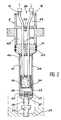
- FIG. 2 represents this cell in longitudinal section.
- the conduit 16 which is connected to the circulation line 1 and the conduit 17 which is connected to a tube for discharging the solution in a container 18, open into a transit tank 19. This figure will be described later in detail.
- the spectrometer 7 comprises a source 20, of irradiation of the solution, and a detector 21 of energy peaks of the radiations coming from the irradiated solution; these radiations are for example X-rays and / or gamma rays.
- the source 20 and the detector are known in the state of the art, and are not described here in detail.
- the detector 21 has an output which constitutes the output 8 of the spectrometer; this output provides the signal representative of the intensities of the energy peaks corresponding respectively to the different metals contained in the solution. These intensities are proportional to the respective concentrations of the different metals contained in the solution.
- the installation also includes a sealed cylindrical well 22, the irradiation of the circulation cell 6 taking place during the measurements.
- This well is arranged vertically between the irradiation source 20 and the detector 21, to irradiate the solution in the transit tank 19 (FIG. 2).
- This cylindrical irradiation well is sealed; it comprises a bottom 23, a cylindrical side wall 24 and, at an upper end, an orifice 25 for introducing the circulation cell 6 inside this well.
- the circulation cell 6 is a sealed hollow cylinder containing the transit tank 19.
- This cylinder has an upper base 26 from which the inlet and outlet conduits 16, 17 of the solution open out, and a lower base 27, near which the transit tank 19 is located, inside the cell.
- the upper and lower bases are joined, in leaktight manner, by a cylindrical casing 28; this envelope can also be constituted by several cylindrical envelopes of different diameters, joined by welds not referenced in this figure.
- the introduction of the circulation 6 in the irradiation well 22 shows a volume 30 between the envelope 28 of the cell 6 and the interior of the wall 24 of the irradiation well 22.
- This volume is hermetically sealed, at least near the orifice 25 of the irradiation well 22.
- This hermetic closure can be achieved for example by means of O-rings 31, 32, engaging in grooves of the cylindrical envelope 28 of the cell 6, to be made integral with this one.
- the irradiation cell 6 also includes a volume 33 making it possible to detect a possible leak of the solution, normally contained in the reservoir 19. This leak can also come from the inlet conduits 16 and 17 and evacuation. This volume is located inside the hollow cylinder of cell 6, between the lower base 27 of cell 6, and the bottom 34 of the transit tank 19.
- Means for detecting possible leakage of solution in the detection volume 33 are connected to a visual and / or audible alarm 36. They are constituted, as shown in FIG. 2, by two electrodes 36, 37 which pass through insulating passages and sealed, the lower base 27 of the cell 6 and which open into the detection volume 33. When there is a solution leak in the volume 33, these two electrodes are short-circuited; they are connected to a male connector 38 which cooperates with a female connector 39 sealingly passing through the bottom 23 of the irradiation well 22.
- the leak detection means also comprise means 40 for triggering an alarm, connected to the female connector 39. These alarm triggering means are not described here in detail. They include a continuous power source connected to the electrodes, means for amplifying a short circuit signal between the electrodes, and means for shaping this signal to trigger the alarm, in the event of a short- circuit between the electrodes.
- the circulation cell 6 has, above the transit tank 19, inside the hollow cylinder constituting this cell, an expansion volume constituted for example, in the embodiment shown in FIG. 2, by compartments 41, 42 placed in communication by a conduit 44 and by an orifice provided with a valve 45.
- This expansion volume is intended to contain the solution in the event of a leak coming from the conduits 16, 17, or from the reservoir 19, above this tank.
- protective discs 46, 47 in lead are provided inside the hollow cylinder constituting the circulation cell 6, these discs are respectively located towards the upper and lower parts of this cell, on either side of the transit tank 19. They are not provided when the installation is used to carry out measurements relating to non-radioactive products, which do not emit dangerous radiation.
- the installation further comprises, as shown in FIG. 1, a receptacle 48 for placing the circulation cell 6 on standby; this cell is placed in this receptacle, when no measurement is made.
- This receptacle has the form of a tight, cylindrical support vessel having a bottom 49 and a side wall 50 of cylindrical shape.
- This support vase 48 has at an upper end, an orifice 51 for introducing the circulation cell.
- the receptacle 48 includes means for detecting a possible leak of the solution in the volume 52, between the envelope of the cell 6 and the wall 48 of the support vessel; these detection means are connected to the visual alarm 35 and / or audible 36. They consist, as before, by two electrodes 53, 54 connected to the means 40 for triggering an alarm, via a connector 55 and of a link 56. In the event of a solution leaking into the volume 52, a short circuit is established between the electrodes 53 and 54 and makes it possible to trigger the alarm.
- the alarm triggering means 40 can also be connected to the computer 9 for recording this alarm and viewing it in the results provided by the printer 12 and / or the screen 11. In the event of alarm, the computer 9 stops the circulation of the solution, by controlling the closing of the solenoid valve 15.
- the installation In the embodiment for which the installation is used for measurements relating to radioactive products, as indicated above, it comprises a glove box 13, the pipe 1 passing through this glove box in a sealed manner; the solenoid valve 15 contained in this glove box is controlled by the computer 9, at the moment when measurements have to be triggered.
- the conduits 16, 17 for arrival and discharge of the solution pass through the glove box through a window 57 having a perimeter delimited by a frame 58.
- This frame is hermetically connected by the flexible waterproof sleeve 14 to a part 59 of the upper base 26 of the cell 6. Collars such as 60, 61 make it possible to ensure the desired seal.
- the pipes 16, 17 for supplying and discharging the solution are located in the sleeve 14, the pipe 17 opening as indicated above in the container 18 located in the glove box 13.
- the receptacle 48 of the circulation cell is secured to the glove box 13.
- FIG 3 shows schematically and in longitudinal section, the means 2 for measuring the acidity of the solution.
- These acidity measurement means comprise an enclosure 62 having an inlet orifice 63 and an outlet orifice 64, connected to the circulation pipe 1 so that this enclosure is traversed by the solution.
- These means also include a reference electrode 65 and a measurement electrode 66 immersed in the solution by their ends, inside this enclosure, in a direction perpendicular to that of the circulation of the solution.
- These two electrodes are connected to a voltage measuring device 66, for example a millivoltmeter having an output 3 which constitutes the output providing the signal representative of the acidity of the solution.
- This signal is supplied to the computer 9.
- the electrodes 65, 66 are cylindrical in shape and are surrounded by an electrolyte (not shown in the figure), suitable for measuring the acidity of the solution concerned. These are, for example, PHF100 type electrodes sold by the company TACUSSEL.
- the installation also includes at least one reference cell 67, shown schematically and in longitudinal section in FIG. 4.
- This cell comprises, like the circulation cell, a hollow cylinder 68 with several compartments; it is hermetically closed and contains at its lower part, a tank 69 identical to the transit tank.
- This reservoir is filled with a reference solution, containing masses of known values, of metals in solution.
- This reference cell allows the calibration of the measurements and it is introduced into the irradiation well 22 of FIG. 1 to carry out reference measurements.
- two tubes 70, 71 identical to the solution discharge inlet tubes, which are used in the circulation cell. One of these tubes (70 for example) is used to fill the reservoir 69 with the reference solution.
- tubes 70, 71 are respectively hermetically closed by plugs 72, 73, while the upper part of the hollow cylinder 68 is hermetically closed by a plug 74.
- each glove box has its own flow meters 4, acidity measurement means 2, circulation cell 6, waiting receptacle 48 and flexible handle 14.
- this movable assembly comprises the most expensive means of the 'installation. It is therefore useful to be able to use it to carry out measurements of different solutions arriving respectively at different glove boxes.
- the solution is a solution of nitric acid containing Plutonium, Uranium and Americium in solution.
- the solenoid valve 15 is opened to ensure the circulation of the solution in line 1.
- This solution then circulates in the measurement means d acicity 2, the flow meter 4 and the circulation cell 6, the switching on of the irradiation source 20 and the start of the measurement having been controlled simultaneously by the computer 9.
- the memory 10 of the computer periodically records the values of the acidity, the flow rate and the concentration of the different metals in the solution, supplied respectively by the acidity measurement means 2, the flow meter 4 and the detector 21 of the spectrometer.
- ⁇ designates the absorption coefficient of the material passed through.
- this material contains nitric acid as well as nitrates of Plutonium, Uranium and Americium.
- the absorption coefficient ⁇ is in fact proportional to the sum of the concentrations of nitric acid, plutonium, uranium and americium.
- the concentration of nitric acid is known by means of acidity measurement.
- the measurements of the intensities of the energy peaks supplied by the detector then make it possible to know the concentrations of Plutonium, Uranium and Americium. Knowing these concentrations and the flow rate of the solution makes it possible to deduce the masses of these different metals present in the solution.
- the calculation of the concentrations is an iterative calculation making it possible to correct the values of the intensities of the energy peaks supplied by the detector, these peaks often being associated with parasites and streaks distorting the measurements.
- the calculation program recorded in the memory 10 of the computer makes it possible, from approximate values of the intensities of energy peaks, supplied by the detector and from approximate values of the intensities of energy peaks from reference solutions measured from the reference cells mentioned above, to perform iterative correction calculations, making it possible to best approach the real concentrations of the different metals in the solution.
Landscapes
- Chemical & Material Sciences (AREA)
- Health & Medical Sciences (AREA)
- Life Sciences & Earth Sciences (AREA)
- Immunology (AREA)
- Analytical Chemistry (AREA)
- Biochemistry (AREA)
- General Health & Medical Sciences (AREA)
- General Physics & Mathematics (AREA)
- Physics & Mathematics (AREA)
- Pathology (AREA)
- Engineering & Computer Science (AREA)
- Food Science & Technology (AREA)
- Medicinal Chemistry (AREA)
- Investigating Or Analyzing Materials By The Use Of Electric Means (AREA)
- Investigating Or Analyzing Non-Biological Materials By The Use Of Chemical Means (AREA)
- Analysing Materials By The Use Of Radiation (AREA)
Abstract
Description
La présente invention concerne une installation de mesures en continu et en temps réel de masses de métaux en solution acide et de l'acidité de cette solution. Elle s'applique plus particulièrement aux mesures en continu et en temps réel, de masses de métaux en solution d'acide nitrique, et notamment de masses de Plutonium, d'Uranium et d'Américium provenant d'usines de retraitement de déchets nucléaires et contenus dans cette solution d'acide nitrique.The present invention relates to an installation for continuous and real-time measurements of masses of metals in acid solution and of the acidity of this solution. It applies more particularly to continuous and real-time measurements of masses of metals in solution of nitric acid, and in particular of masses of Plutonium, Uranium and Americium originating from nuclear waste reprocessing plants and contained in this nitric acid solution.
Il n'existe pas actuellement d'installation permettant de mesurer en continu et en temps réel, des masses métalliques en solution acide et notamment de mesurer des masses d'Uranium, de Plutonium et d'Américium contenus dans une solution d'acide nitrique provenant d'une usine de retraitement de déchets nucléaires.There is currently no installation allowing continuous measurement in real time of metallic masses in acid solution and in particular to measure masses of Uranium, Plutonium and Americium contained in a solution of nitric acid originating from of a nuclear waste reprocessing plant.
La seule méthode connue pour effectuer de telles mesures de masses ne permet pas d'obtenir des résultats en continu et en temps réel. Elle ne met pas en oeuvre un ensemble autonome pouvant être qualifié "d'installation de mesure". En effet, selon cette méthode connue, on prélève un faible échantillon de la solution acide contenant des masses métalliques et on effectue des dosages permettant de déterminer les valeurs de ces masses métalliques en solution.The only known method for carrying out such mass measurements does not make it possible to obtain results continuously and in real time. It does not use an autonomous unit which can be qualified as a "measuring installation". Indeed, according to this known method, a small sample of the acid solution containing metallic masses is taken and assays are carried out making it possible to determine the values of these metallic masses in solution.
Cette méthode présente de nombreux inconvénients : les mesures des masses effectuées par dosage sont réalisées à partir d'échantillons de la solution et non à partir de cette solution en totalité. Ces mesures ne sont donc pas effectuées en continu et en temps réel, elles sont très longues à mettre en oeuvre (plusieurs heures) et elles ne sont valables que pour un faible échantillon de la solution. De plus, notamment pour les mesures de masses d'uranium, de plutonium et d'américium, dans une solution d'acide nitrique, ces opérations de dosage doivent être effectuées manuellement, à l'intérieur d'une boîte à gants ; ces manipulations peuvent être dangereuses.This method has many disadvantages: the mass measurements carried out by assay are carried out from samples of the solution and not from this solution in its entirety. These measurements are therefore not carried out continuously and in real time, they are very long to implement (several hours) and they are only valid for a small sample of the solution. In addition, in particular for the measurement of uranium, plutonium and americium masses, in a nitric acid solution, these dosing operations must be carried out manually, inside a glove box; these manipulations can be dangerous.
L'invention a pour but de remédier à ces inconvénients et notamment de réaliser une installation de mesures agissant en continu et en temps réel fournissant rapidement des résultats de mesures, concernant l'ensemble de la solution et sans nécessiter de manipulations longues et dangereuses.The object of the invention is to remedy these drawbacks and in particular to produce a measurement installation acting continuously and in real time rapidly supplying measurement results, concerning the entire solution and without requiring long and dangerous manipulations.
Ces buts sont atteints en faisant circuler l'ensemble de la solution dans l'installation et en effectuant des mesures de débit de la solution, d'acidité, et de concentrations des métaux dans cette solution en circulation.These goals are achieved by circulating the entire solution in the installation and by carrying out measurements of the flow rate of the solution, of acidity, and of concentrations of metals in this circulating solution.
L'invention a pour objet une installation de mesure en continu et en temps réel de masses de métaux contenus en solution acide et de l'acidité de cette solution, caractérisée en ce qu'elle comporte une conduite de circulation de cette solution, des moyens reliés à la conduite et traversés par la solution, pour mesurer l'acidité de cette solution, une sortie de ces moyens de mesure d'acidité fournissant un signal représentatif de la valeur de cette acidité, un débitmètre relié à la conduite et traversé par la solution, pour fournir sur une sortie un signal représentatif de la valeur du débit de cette solution, une cellule de circulation de la solution, reliée à la conduite et traversée par la solution, un spectromètre agissant sur la cellule de circulation pour fournir sur une sortie un signal représentatif de l'intensité des pics d'énergie correspondant respectivement aux valeurs des concentrations des métaux dans la solution, et un ordinateur relié aux sorties des moyens de mesure d'acidité, du spectromètre et du débitmètre, cet ordinateur étant aussi relié à une mémoire dans laquelle est enregistré un programme de calcul des masses respectives desdits métaux, à partir des valeurs desdites concentrations respectives, et des valeurs de l'acidité et du débit.The subject of the invention is an installation for continuous and real-time measurement of the masses of metals contained in acid solution and of the acidity of this solution, characterized in that it comprises a pipe for circulation of this solution, means connected to the pipe and crossed by the solution, to measure the acidity of this solution, an output of these acidity measurement means providing a signal representative of the value of this acidity, a flow meter connected to the pipe and crossed by the solution, to provide a signal representative of the value of the flow rate of this solution on an output, a solution circulation cell, connected to the pipe and crossed by the solution, a spectrometer acting on the circulation cell to provide an output a signal representative of the intensity of the energy peaks corresponding respectively to the values of the concentrations of metals in the solution, and a computer connected to the outputs of the acidity measurement means, of the spectrometer and of the flow meter, this computer also being linked to a memory in which is recorded a program for calculating the respective masses of said metals, from the values of said respective concentrations, and the values of acidity and of flow rate.
Selon une autre caractéristique de l'invention, ladite cellule de circulation comporte un conduit d'arrivée de la solution relié à ladite conduite de circulation et débouchant dans un réservoir de transit, et un conduit d'évacuation de la solution dudit réservoir de transit vers un récipient de stockage, ledit spectromètre comportant une source d'irradiation de la solution, un détecteur de pics d'énergie, ayant une sortie constituant ladite sortie du spectromètre, et un puits cylindrique étanche d'irradiation de ladite cellule de circulation au cours des mesures, disposé verticalement entre la source d'irradiation et le détecteur, pour irradier la solution dans le réservoir de transit, ce puits d'irradiation ayant un fond et une paroi latérale cylindique et, à une extrémité supérieure, un orifice d'introduction de ladite cellule à l'intérieur dudit puits.According to another characteristic of the invention, said circulation cell comprises a solution inlet pipe connected to said circulation pipe and opening into a transit tank, and a solution discharge pipe from said transit tank to a storage container, said spectrometer comprising a source of irradiation of the solution, an energy peak detector, having an outlet constituting said outlet of the spectrometer, and a sealed cylindrical well for irradiation of said circulation cell during measures, arranged vertically between the irradiation source and the detector, to irradiate the solution in the transit tank, this irradiation well having a bottom and a cylindrical side wall and, at an upper end, an orifice for introducing said cell inside said well.
Selon une autre caractéristique, ladite cellule de circulation est un cylindre creux étanche contenant ledit réservoir de transit, ce cylindre représentant une base supérieure de laquelle débouchent lesdits conduits d'arrivée et d'évacuation de la solution, une base inférieure à proximité de laquelle est situé ledit réservoir de transit, et une enveloppe cylindrique solidaire desdites bases, l'introduction de ladite cellule de circulation dans ledit puits d'irradiation faisant apparaïtre un volume entre ladite enveloppe cylindrique de la cellule et l'intérieur dudit puits, ce volume étant fermé hermétiquement au moins à proximité de l'orifice dudit puits d'irradiation, par des joints solidaires de ladite enveloppe.According to another characteristic, said circulation cell is a sealed hollow cylinder containing said transit tank, this cylinder representing an upper base from which open said solution inlet and outlet conduits, a lower base near which is located said transit tank, and an envelope cylindrical integral with said bases, the introduction of said circulation cell into said irradiation well showing a volume between said cylindrical envelope of the cell and the interior of said well, this volume being hermetically sealed at least near the orifice of said irradiation well, by joints integral with said envelope.
Selon une autre caractéristique, la cellule de circulation comporte un volume de détection de fuites de solution, situé à l'intérieur dudit cylindre entre la base inférieure de ce cylindre et le réservoir de transit, l'installation comportant en outre des moyens de détection de fuite de solution dans le volume de détection, ces moyens de détection étant reliés à une alarme.According to another characteristic, the circulation cell comprises a volume for detecting solution leaks, located inside said cylinder between the lower base of this cylinder and the transit tank, the installation further comprising means for detecting solution leak in the detection volume, these detection means being connected to an alarm.
Selon une autre caractéristique, les moyens de détection de fuite de solution comportent deux électrodes situées dans le volume de détection, ces électrodes étant reliées à des moyens de déclenchement d'alarme, par des moyens de connexion traversant la base inférieure de la cellule de circulation et le fond dudit puits d'irradiation.According to another characteristic, the solution leak detection means comprise two electrodes located in the detection volume, these electrodes being connected to alarm triggering means, by connection means passing through the lower base of the circulation cell. and the bottom of said irradiation well.
Selon une autre caractéristique, la cellule de circulation comporte, au-dessus du réservoir de transit, à l'intérieur dudit cylindre, un volume d'expansion destiné à contenir la solution en cas de fuite.According to another characteristic, the circulation cell comprises, above the transit tank, inside said cylinder, an expansion volume intended to contain the solution in the event of a leak.
Selon une autre caractéristique, la cellule de circulation comporte en outre un réceptacle d'attente de la cellule de circulation, pour la mise en attente de celle-ci, lorsqu'aucune mesure n'est effectuée, ce réceptacle ayant la forme d'un vase-support étanche, cylindrique, ayant un fond, une paroi latérale cylindrique et une extrémité supérieure présentant un orifice d'introduction de la cellule de circulation, l'introduction de la cellule de circulation dans le vase-support faisant apparaître un volume entre l'enveloppe cylindrique de la cellule et la paroi du vase-support, ce réceptacle comportant des moyens de détection de fuite de solution dans le volume entre l'enveloppe de la cellule et la paroi du vase-support, ces moyens étant reliés à ladite alarme.According to another characteristic, the circulation cell further comprises a receptacle for waiting for the circulation cell, for placing the latter on standby, when no measurement is made, this receptacle having the form of a watertight, cylindrical support vessel having a bottom, a cylindrical side wall and an upper end having an orifice for introducing the circulation cell, the introduction of the circulation cell into the support vessel showing a volume between the cylindrical envelope of the cell and the wall of the support vessel, this receptacle comprising means for detecting a solution leak in the volume between the cell envelope and the wall of the support vessel, these means being connected to said alarm.
Selon une autre caractéristique, le débitmètre et les moyens de mesure d'acidité sont situés dans une boîte à gants, ladite conduite traversant cette boîte à gants de façon étanche, lesdits conduits d'arrivée et d'évacuation de la solution traversant cette boîte à gants par une fenêtre ayant un pourtour délimité par un cadre, ce cadre étant relié hermétiquement par une manche souple étanche, à la base supérieure de la cellule de circulation, lesdits conduits d'arrivée et d'évacuation étant situées dans ladite manche, ledit conduit d'évacuation débouchant dans un récipient situé dans la boîte à gants, ledit réceptacle d'attente étant solidaire de la boîte à gants.According to another characteristic, the flow meter and the acidity measurement means are located in a glove box, said pipe passing through this glove box in a sealed manner, said inlet and outlet pipes for the solution passing through this box. gloves through a window having a periphery delimited by a frame, this frame being hermetically connected by a flexible tight sleeve, to the upper base of the circulation cell, said inlet and outlet ducts being located in said sleeve, said duct outlet opening into a container located in the glove box, said holding receptacle being integral with the glove box.
Selon une autre caractéristique, le spectromètre, l'ordinateur, les moyens de déclenchement d'alarme, l'alarme et le puits d'irradiation, forment un ensemble déplaçable à proximité de différentes boîtes à gants, chaque boîte à gants ayant ses propres débitmètre , moyens de mesure d'acidité, cellule de circulation, réceptacle d'attente et manche souple.According to another characteristic, the spectrometer, the computer, the alarm triggering means, the alarm and the irradiation well, form a unit which can be moved close to different glove boxes, each glove box having its own flow meter. , acidity measurement means, circulation cell, holding receptacle and flexible handle.
Selon une autre caractéristique, l'installation est destinée à la mesure des masses de Plutonium, d'Uranium et d'Américium, en solution d'acide nitrique, et à la mesure d'acidité de cette solution.According to another characteristic, the installation is intended for measuring the masses of Plutonium, Uranium and Americium, in nitric acid solution, and for measuring the acidity of this solution.
Selon une autre caractéristique les moyens de mesure d'acidité comportent une enceinte ayant un orifice d'entrée et un orifice de sortie de la solution, reliés à ladite conduite de circulation pour que cette enceinte soit traversée par la solution, une électrode de référence, et une électrode de mesure, plongeant dans la solution, à l'intérieur de ladite enceinte, dans une direction perpendiculaire à celle de la circulation de solution, ces deux électrodes étant reliées à un appareil de mesure de tension ayant une sortie constituant ladite sortie qui fournit un signal représentatif de l'acidité de la solution.According to another characteristic, the means of acidity measurement comprise an enclosure having an inlet orifice and an outlet for the solution, connected to said circulation pipe so that this enclosure is traversed by the solution, a reference electrode, and a measuring electrode, plunging in the solution, inside said enclosure, in a direction perpendicular to that of the circulation of solution, these two electrodes being connected to a voltage measuring device having an output constituting said output which provides a signal representative of the acidity of the solution.
Les caractéristiques et avantages de l'invention ressortiront mieux de la description qui va suivre, donnée en référence aux dessins annexés dans lesquels :
- - la figure 1 représente schématiquement une installation de mesure conforme à l'invention,
- - la figure 2 représente schématiquement et en coupe longitudinale, une cellule de circulation de la solution, appartenant à l'installation de l'invention,
- - la figure 3 représente schématiquement et en coupe, des moyens de mesures d'acidité de la solution, appartenant à l'installation de l'invention,
- - la figure 4 représente schématiquement et en coupe longitudinale une cellule de référence utilisée dans l'installation de l'invention.
- FIG. 1 diagrammatically represents a measuring installation in accordance with the invention,
- FIG. 2 schematically and in longitudinal section, a cell for circulation of the solution, belonging to the installation of the invention,
- FIG. 3 shows diagrammatically and in section, means for measuring the acidity of the solution, belonging to the installation of the invention,
- - Figure 4 shows schematically and in longitudinal section a reference cell used in the installation of the invention.
L'installation conforme à l'invention, représentée schématiquement sur la figure 1 comporte une conduite 1 de circulation de la solution acide contenant des masses de métaux, en solution qu'on souhaite déterminer. Elle comporte aussi des moyens 2 reliés à la conduite 1 et traversés par la solution, pour mesurer l'acidité de celle-ci. Une sortie 3 de ces moyens de mesure 2 fournit comme on le verra plus loin en détail, un signal représentatif de la valeur de cette acidité. La solution en circulation dans la conduite 1 provient d'une enceinte de stockage, non représentée.The installation according to the invention, shown diagrammatically in FIG. 1, comprises a pipe 1 for circulating the acid solution containing masses of metals, in solution which it is desired to determine. It also includes means 2 connected to line 1 and crossed by the solution, to measure the acidity of the latter. An
Un débitmètre 4 est relié à la conduite 1, à la suite des moyens de mesure d'acidité 2. Ce débitmètre est traversé par la solution et fournit sur une sortie 5 un signal représentatif du débit de cette solution dans la conduite 1. Il est de type électromagnétique par exemple et ne sera pas décrit ici en détail.A
L'installation comporte aussi une cellule 6 de circulation de la solution, cette cellule est reliée à la conduite 1, par exemple à la suite du débitmètre 4. Elle est traversée par la solution et sera décrite plus loin en détail.The installation also includes a cell 6 for circulation of the solution, this cell is connected to the pipe 1, for example following the
Enfin, l'installation comporte un spectromètre 7 agissant sur la cellule de circulation 6 et fournissant sur une sortie 8, un signal représentatif de l'intensité des pics d'énergie correspondant respectivement aux valeurs des concentrations des différents métaux contenus dans la solution acide. Un ordinateur 9 est relié aux sorties 3, 5, 8 des moyens de mesure d'acidité 2, du débitmètre 4 et du spectromètre 7. Cette ordinateur est aussi relié à une mémoire 10 dans laquelle est enregistré un programme de calcul des masses respectives des métaux présent dans la solution acide ; ce calcul est effectué à partir des valeurs des concentrations respectives de ces métaux et des valeurs d'acidité et de débit de la solution. Ce calcul sera décrit plus loin en détail. L'ordinateur peut être muni d'un écran de visualisation 11 et être relié à une imprimante 12 permettant d'imprimer les résultats des mesures.Finally, the installation comprises a spectrometer 7 acting on the circulation cell 6 and providing on an
Dans un premier mode de réalisation, l'installation est utilisée pour des mesures de masses de métaux non radioactifs, on n'utilise alors pas de moyen de protection particulier ; dans un deuxième mode de réalisation l'installation est utilisée pour des mesures de masses de métaux radioactifs tels que le plutonium, l'uranium et l'américium ; l'installation comporte alors une boîte à gants 13 ainsi que différents éléments de protection tels qu'une manche souple étanche 14, qui seront décrits plus loin en détail.In a first embodiment, the installation is used for mass measurements of non-radioactive metals, no special means of protection are used; in a second embodiment, the installation is used for mass measurements of radioactive metals such as plutonium, uranium and americium; the installation then comprises a
On a aussi représenté sur la figure 1, une électrovanne 15 permettant de commander, comme on le verra plus loin en détail, la circulation ou l'arrêt de la circulation de la solution dans la conduite 1.FIG. 1 also shows a
La cellule 6 de circulation de la solution comporte un conduit 16 d'arrivée de cette solution, et un conduit 17 d'évacuation de celle-ci. Le conduit d'arrivée 16 est relié à la conduite de circulation 1, par exemple à la suite du débitmètre 5. Le conduit d'évacuation 17 peut déboucher, par exemple, dans un bac de récupération 18 de la solution.The solution circulation cell 6 comprises a
La structure de la cellule 6 de circulation de la solution sera mieux comprise à l'aide de la figure 2 qui représente cette cellule en coupe longitudinale. Le conduit 16 qui est relié à la conduite de circulation 1 et le conduit 17 qui est relié à une tubulure d'évacuation de la solution dans un récipient 18, débouchent dans un réservoir de transit 19. Cette figure sera décrite plus loin en détail.The structure of the cell 6 for circulation of the solution will be better understood with the aid of FIG. 2 which represents this cell in longitudinal section. The
En se référant à nouveau à la figure 1, le spectromètre 7 comporte une source 20, d'irradiation de la solution, et un détecteur 21 de pics d'énergie des radiations issus de la solution irradiée ; ces radiations sont par exemple des rayons X et/ou des rayons gamma . La source 20 et le détecteur sont connus dans l'état de la technique, et ne sont pas décrits ici en détail. Le détecteur 21 possède une sortie qui constitue la sortie 8 du spectromètre ; cette sortie fournit le signal représentatif des intensités des pics d'énergie correspondant respectivement aux différents métaux contenus dans la solution. Ces intensités sont proportionnelles aux concentrations respectives des différents métaux contenus dans la solution. L'installation comporte aussi un puits cylindrique étanche 22, l'irradiation de la cellule de circulation 6 ayant lieu au cours des mesures. Ce puits est disposé verticalement entre la source d'irradiation 20 et le détecteur 21, pour irradier la solution dans le réservoir de transit 19 (figure 2). Ce puits cylindrique d'irradiation est étanche ; il comporte un fond 23, une paroi latérale cylindrique 24 et, à une extrémité supérieure, un orifice 25 d'introduction de la cellule de circulation 6 à l'intérieur de ce puits.Referring again to FIG. 1, the spectrometer 7 comprises a
Comme le montre la figure 2, la cellule de circulation 6 est un cylindre creux étanche contenant le réservoir de transit 19. Ce cylindre présente une base supérieure 26 de laquelle débouchent les conduits d'arrivée et d'évacuation 16, 17 de la solution, et une base inférieure 27, à proximité de laquelle est situé le réservoir de transit 19, à l'intérieur de la cellule. Les bases supérieure et inférieure sont réunies, de façon étanche, par une enveloppe cylindrique 28 ; cette enveloppe peut d'ailleurs être constituée par plusieurs enveloppes cylindriques de diamètres différents, réunies par des soudures non référencées sur cette figure.As shown in FIG. 2, the circulation cell 6 is a sealed hollow cylinder containing the
En se référant à nouveau à la figure 1, on constate que l'introduction de la cellule de circulation 6 dans le puits d'irradiation 22, fait apparaître un volume 30 entre l'enveloppe 28 de la cellule 6 et l'intérieur de la paroi 24 du puits d'irradiation 22. Ce volume est fermé hermétiquement, au moins à proximité de l'orifice 25 du puits d'irradiation 22. Cette fermeture hermétique peut être réalisée par exemple au moyen de joints toriques 31, 32, s'engageant dans des gorges de l'enveloppe cylindrique 28 de la cellule 6, pour être rendus solidaires de celle-ci.Referring again to FIG. 1, it can be seen that the introduction of the circulation 6 in the irradiation well 22, shows a
Comme le montre plus précisément la figure 2 la cellule d'irradiation 6 comporte aussi un volume 33 permettant de détecter une fuite éventuelle de la solution, normalement contenue dans le réservoir 19. Cette fuite peut aussi provenir des conduits 16 et 17 d'arrivée et d'évacuation. Ce volume est situé à l'intérieur du cylindre creux de la cellule 6, entre la base inférieure 27 de la cellule 6, et le fond 34 du réservoir de transit 19.As shown more precisely in FIG. 2, the irradiation cell 6 also includes a
Des moyens de détection de fuite éventuelle de solution dans le volume de détection 33 sont reliés à une alarme visuelle 35 et/ou sonore 36. Ils sont constitués comme le montre la figure 2, par deux électrodes 36, 37 qui traversent par des passages isolants et étanches, la base inférieure 27 de la cellule 6 et qui débouchent dans le volume de détection 33. Lorsqu'il se produit une fuite de solution dans le volume 33, ces deux électrodes sont mises en court-circuit ; elles sont reliées à un connecteur mâle 38 qui coopère avec un connecteur femelle 39 traversant de façon étanche le fond 23 du puits d'irradiation 22. Les moyens de détection de fuite comportent aussi des moyens 40 de déclenchement d'alarme, reliés au connecteur femelle 39. Ces moyens de déclenchement d'alarme ne sont pas décrits ici en détail. Ils comportent notamment une source d'alimentation continue reliée aux électrodes, des moyens d'amplification d'un signal de court-circuit entre les électrodes, et des moyens de mise en forme de ce signal pour déclencher l'alarme, en cas de court-circuit entre les électrodes.Means for detecting possible leakage of solution in the
La cellule de circulation 6 présente, au-dessus du réservoir de transit 19, à l'intérieur du cylindre creux constituant cette cellule, un volume d'expansion constitué par exemple, dans le mode de réalisation représenté sur la figure 2, par des compartiments 41, 42 mis en communication par un conduit 44 et par un orifice muni d'une soupape 45. Ce volume d'expansion est destiné à contenir la solution en cas de fuite provenant des conduits 16, 17, ou du réservoir 19, au-dessus de ce réservoir.The circulation cell 6 has, above the
Dans le mode de réalisation pour lequel l'installation est utilisée pour effectuer des mesures de masses de plutonium, d'uranium et d'américium contenus dans des solutions provenant d'usines de retraitement de déchets nucléaires, des disques de protection 46, 47 en plomb sont prévus à l'intérieur du cylindre creux constituant la cellule de circulation 6, ces disques sont respectivement situés vers les parties supérieure et inférieure de cette cellule, de part et d'autre du réservoir de transit 19. Ils ne sont pas prévus lorsque l'installation est utilisée pour effectuer des mesures concernant des produits non radioactifs, n'émettant pas de rayonnements dangereux.In the embodiment for which the installation is used to measure the masses of plutonium, uranium and americium contained in solutions originating from nuclear waste reprocessing plants,
L'installation comporte en outre, comme le montre la figure 1 un réceptacle 48 de mise en attente de la cellule de circulation 6 ; cette cellule est placée dans ce réceptacle, lorsqu'aucune mesure n'est effectuée. Ce réceptacle a la forme d'un vase-support étanche, cylindrique, ayant un fond 49 et une paroi latérale 50 de forme cylindrique. Ce vase-support 48 présente à une extrémité supérieure, un orifice 51 d'introduction de la cellule de circulation.The installation further comprises, as shown in FIG. 1, a
L'introduction de la cellule de circulation 6 dans le réceptacle 48 fait apparaître une volume 52 entre l'enveloppe cylindrique de la cellule 6 et la paroi latérale 50 du vase-support. Dans le mode de réalisation où l'installation est utilisée pour des mesures concernant des produits radioactifs, le réceptacle 48 comporte des moyens de détection d'une fuite éventuelle de la solution dans le volume 52, entre l'enveloppe de la cellule 6 et la paroi 48 du vase-support ; ces moyens de détection sont reliés à l'alarme visuelle 35 et/ou sonore 36. Ils sont constitués, comme précédemment, par deux électrodes 53, 54 reliées aux moyens 40 de déclenchement d'alarme, par l'intermédiaire d'un connecteur 55 et d'une liaison 56. En cas de fuite de solution dans le volume 52, un court-circuit s'établit entre les électrodes 53 et 54 et permet de déclencher l'alarme. Les moyens de déclenchement d'alarme 40 peuvent d'ailleurs être reliés à l'ordinateur 9 pour l'enregistrement de cette alarme et sa visualisation dans les résultats fournis par l'imprimante 12 et/ou l'écran 11. En cas d'alarme, l'ordinateur 9 arrête la circulation de la solution, en commandant la fermeture de l'électrovanne 15.The introduction of the circulation cell 6 into the
Dans le mode de réalisation pour lequel l'installation est utilisée pour des mesures concernant des produits radioactifs, comme indiqué plus haut, celle-ci comporte une boîte à gants 13, la conduite 1 traversant cette boîte à gants de façon étanche ; l'électrovanne 15 contenue dans cette boîte à gants est commandée par l'ordinateur 9, au moment où des mesures doivent être déclenchées. Les conduits 16, 17 d'arrivée et d'évacuation de la solution traversent la boîte à gants par une fenêtre 57 ayant un pourtour délimité par un cadre 58. Ce cadre est relié hermétiquement par la manche souple étanche 14 à une partie 59 de la base supérieure 26 de la cellule 6. Des colliers tels que 60, 61 permettent d'assurer l'étanchéité souhaitée. Les conduits 16, 17 d'arrivée et d'évacuation de la solution sont situés dans la manche 14, le conduit 17 débouchant comme indiqué plus haut dans le récipient 18 situé dans la boîte à gants 13. Dans ce mode de réalisation, le réceptacle 48 de la cellule de circulation est solidaire de la boîte à gants 13.In the embodiment for which the installation is used for measurements relating to radioactive products, as indicated above, it comprises a
La figure 3 représente schématiquement et en coupe longitudinale, les moyens 2 de mesure de l'acidité de la solution. Ces moyens de mesure d'acidité comportent une enceinte 62 ayant un orifice d'entrée 63 et un orifice de sortie 64, reliés à la conduite de circulation 1 pour que cette enceinte soit traversée par la solution. Ces moyens comportent aussi une électrode de référence 65 et une électrode de mesure 66 plongeant dans la solution par leurs extrémités, à l'intérieur de cette enceinte, dans une direction perpendiculaire à celle de la circulation de la solution. Ces deux électrodes sont reliées à un appareil de mesure de tension 66, par exemple un millivoltmètre ayant une sortie 3 qui constitue la sortie fournissant le signal représentatif de l'acidité de la solution. Ce signal est fourni à l'ordinateur 9. Les électrodes 65, 66 sont de forme cylindrique et sont entourées d'un électrolyte (non représenté sur la figure), approprié à la mesure de l'acidité de la solution concernée. Ce sont par exemple des électrodes de type PHF100 commercialisées par la société TACUSSEL.Figure 3 shows schematically and in longitudinal section, the means 2 for measuring the acidity of the solution. These acidity measurement means comprise an
Pour des raisons qui seront expliquées plus loin en détail, l'installation comporte aussi, au moins une cellule de référence 67, représentée schématiquement et en coupe longitudinale sur la figure 4. Cette cellule comporte, comme la cellule de circulation un cylindre creux 68 à plusieurs compartiments ; elle est hermétiquement fermée et contient à sa partie inférieure, un réservoir 69 identique au réservoir de transit. Ce réservoir est rempli par une solution de référence, contenant des masses de valeurs connues, de métaux en solution. Cette cellule de référence permet l'étalonnage des mesures et elle est introduite dans le puits d'irradiation 22 de la figure 1 pour effectuer des mesures de référence. On a aussi représenté sur cette figure deux tubes 70, 71 identiques aux tubes d'arrivée d'évacuation de la solution, qui sont utilisés dans la cellule de circulation. L'un de ces tubes (70 par exemple) sert au remplissage du réservoir 69 par la solution de référence. Ces deux tubes, le réservoir 69, ainsi que toute la partie inférieure de la cellule de référence présentent des dimensions et une structure identiques à celles de la cellule de circulation, de manière à ne pas fausser les mesures de référence. Après remplissage du réservoir 69 par la solution de référence, les tubes 70, 71 sont respectivement fermés hermétiquement par des bouchons 72, 73, tandis que la partie supérieure du cylindre creux 68 est fermée hermétiquement par un bouchon 74.For reasons which will be explained later in detail, the installation also includes at least one
Dans le mode de réalisation où l'installation est utilisée pour des mesures concernant des produits radioactifs, le spectromètre 7, le puits d'irradiation 22, l'ordinateur 9 ainsi que l'imprimante 12 et la mémoire 10 qui lui sont associées, les moyens de déclenchement d'alarme 40 et l'alarme (35 ou 36), forment un ensemble déplaçable à proximité de différentes boîtes à gants correspondant respectivement à différentes solutions contenant des produits radioactifs. Dans ce cas, chaque boîte à gants comporte ses propres débitmètres4, moyens de mesure d'acidité 2, cellule de circulation 6, réceptacle d'attente 48 et manche souple 14. En effet, cet ensemble déplaçable comporte les moyens les plus coûteux de l'installation. Il est donc utile de pouvoir l'utiliser pour effectuer des mesures de différentes solutions parvenant respectivement à différentes boîtes à gants.In the embodiment where the installation is used for measurements relating to radioactive products, the spectrometer 7, the irradiation well 22, the computer 9 as well as the
L'installation qui vient d'être décrite fonctionne de la manière suivante :
- on suppose par exemple que la solution est une solution d'acide nitrique contenant du Plutonium, de l'Uranium et de l'Américium en solution. A partir du clavier de l'ordinateur 9 et du programme contenu dans sa mémoire 10, on commande l'ouverture de l'électrovanne 15 pour assurer la circulation de la solution dans la conduite 1. Cette solution circule alors dans les moyens de mesure d'acicité 2, le débitmètre 4 et la cellule de circulation 6, la mise en marche de la source d'irradiation 20 et le début de la mesure ayant été commandés simultanément par l'ordinateur 9. Au cours de cette circulation la mémoire 10 de l'ordinateur enregistre périodiquement les valeurs de l'acidité, du débit et de la concentration des différents métaux dans la solution, fournis respectivement par les moyens de mesure d'acidité 2, le débitmètre 4 et le détecteur 21 du spectromètre.The installation which has just been described works in the following way:
- it is assumed for example that the solution is a solution of nitric acid containing Plutonium, Uranium and Americium in solution. From the computer keyboard 9 and from the program contained in its
La mesure de l'acidité de la solution permet de corriger dans les intensités des pics d'énergie fournis par le détecteur 22 du spectromètre, l'effet de la présence d'acide nitrique. On sait en effet que si l'on désigne par I₂ l'intensité des rayonnements issus d'une solution d'épaisseur x, cette solution étant irradiée par des rayonnements d'amplitude I₁, il est possible d'écrire I₂ =I₁e-µx.The measurement of the acidity of the solution makes it possible to correct, in the intensities of the energy peaks supplied by the
Dans cette relation µ désigne le coefficient d'absorption de la matière traversée. Or, dans l'exemple considéré, cette matière contient de l'acide nitrique ainsi que des nitrates de Plutonium, d'Uranium et d'Américium.In this relation µ designates the absorption coefficient of the material passed through. However, in the example considered, this material contains nitric acid as well as nitrates of Plutonium, Uranium and Americium.
Le coefficient d'absorption µ est en fait proportionnel à la somme des concentrations en Acide nitrique, en Plutonium, en Uranium et en Américium.The absorption coefficient µ is in fact proportional to the sum of the concentrations of nitric acid, plutonium, uranium and americium.
La concentration d'acide nitrique est connue grâce aux moyens de mesure d'acidité. Les mesures des intensités des pics d'énergie fournies par le détecteur, permettent alors de connaître les concentrations en Plutonium, en Uranium et Américium. La connaissance de ces concentrations et du débit de la solution permet d'en déduire les masses de ces différents métaux présents dans la solution.The concentration of nitric acid is known by means of acidity measurement. The measurements of the intensities of the energy peaks supplied by the detector then make it possible to know the concentrations of Plutonium, Uranium and Americium. Knowing these concentrations and the flow rate of the solution makes it possible to deduce the masses of these different metals present in the solution.
Le calcul des concentrations est un calcul itératif permettant de corriger les valeurs des intensités des pics d'énergie fournis par le détecteur, ces pics étant souvent assortis de parasites et de traînées faussant les mesures. A cet effet, le programme de calcul enregistré dans la mémoire 10 de l'ordinateur permet, à partir des valeurs approchées des intensités des pics d'énergie, fournis par le détecteur et à partir des valeurs approchantes des intensités de pics d'énergie de solutions de référence mesurées à partir des cellules de référence mentionnées plus haut, d'effectuer des calculs itératifs de correction, permettant d'approcher au mieux les concentrations réelles des différents métaux dans la solution.The calculation of the concentrations is an iterative calculation making it possible to correct the values of the intensities of the energy peaks supplied by the detector, these peaks often being associated with parasites and streaks distorting the measurements. To this end, the calculation program recorded in the
Claims (12)
Applications Claiming Priority (2)
| Application Number | Priority Date | Filing Date | Title |
|---|---|---|---|
| FR8905126 | 1989-04-18 | ||
| FR8905126A FR2645966B1 (en) | 1989-04-18 | 1989-04-18 | INSTALLATION OF CONTINUOUS AND REAL-TIME MEASUREMENTS, METAL MASSES IN ACID SOLUTION, AND THE ACIDITY OF THIS SOLUTION |
Publications (1)
| Publication Number | Publication Date |
|---|---|
| EP0394108A1 true EP0394108A1 (en) | 1990-10-24 |
Family
ID=9380853
Family Applications (1)
| Application Number | Title | Priority Date | Filing Date |
|---|---|---|---|
| EP90401011A Withdrawn EP0394108A1 (en) | 1989-04-18 | 1990-04-12 | Installation for continuous and real-time measurements of metal masses in acid solution, and of the acidity of this solution |
Country Status (4)
| Country | Link |
|---|---|
| US (1) | US5164160A (en) |
| EP (1) | EP0394108A1 (en) |
| JP (1) | JPH02296148A (en) |
| FR (1) | FR2645966B1 (en) |
Families Citing this family (4)
| Publication number | Priority date | Publication date | Assignee | Title |
|---|---|---|---|---|
| FR2779523B1 (en) * | 1998-06-09 | 2000-08-11 | Grp Pour L Evaluation Des Mesu | MULTI-PARAMETER SENSOR FOR METAL DETECTION, PARTICULARLY IN RELEASE WATER OR IN FILTERED WATER, IN A SANITATION SYSTEM, AND METHOD USING THE SAME |
| US7780065B2 (en) | 1999-11-03 | 2010-08-24 | Vermaat Technics B.V. | Method and device for welding pipes |
| NL1013477C2 (en) * | 1999-11-03 | 2001-05-04 | Vermaat Technics Bv | Method and device for welding pipes. |
| CN112987117B (en) * | 2021-02-08 | 2022-07-29 | 东华理工大学 | Uranium ore quantitative conversion coefficient solving method based on natural gamma energy spectrum logging multi-characteristic peak combination |
Citations (2)
| Publication number | Priority date | Publication date | Assignee | Title |
|---|---|---|---|---|
| FR2236168A1 (en) * | 1973-07-03 | 1975-01-31 | Amf Inc | |
| US4512853A (en) * | 1982-05-18 | 1985-04-23 | Olin Corporation | Method of monitoring pH |
Family Cites Families (13)
| Publication number | Priority date | Publication date | Assignee | Title |
|---|---|---|---|---|
| US2998520A (en) * | 1958-07-25 | 1961-08-29 | Gen Dynamics Corp | Fluid flow regulator |
| US3531644A (en) * | 1967-01-31 | 1970-09-29 | Mallinckrodt Chemical Works | Packaging assembly for radioactive materials |
| US3791221A (en) * | 1972-04-07 | 1974-02-12 | Warner Lambert Co | Dissolution testing device |
| US3844719A (en) * | 1972-06-01 | 1974-10-29 | Ppg Industries Inc | Mercury metal analyzer |
| FR2245249A5 (en) * | 1973-09-25 | 1975-04-18 | Erap Elf Entr Rech Activ Petro | |
| US3898042A (en) * | 1974-01-02 | 1975-08-05 | Dow Chemical Co | Method and apparatus for continuously determining total copper in an aqueous stream |
| JPS55136958A (en) * | 1979-04-14 | 1980-10-25 | Olympus Optical Co Ltd | Automatic analyzer |
| JPS6147551A (en) * | 1984-08-14 | 1986-03-08 | Nippon Kokan Kk <Nkk> | Automatic analyzer for alloy-plated film |
| GB8522126D0 (en) * | 1985-09-06 | 1985-10-09 | Tytronics Inc | Sample monitoring arrangement |
| US4766550A (en) * | 1985-10-30 | 1988-08-23 | Westinghouse Electric Corp. | Automatic on-line chemistry monitoring system |
| JPS62233751A (en) * | 1986-04-04 | 1987-10-14 | Toshiba Corp | Acid concentration measuring instrument |
| US4908676A (en) * | 1987-12-18 | 1990-03-13 | Bio-Recovery Systems, Inc. | Sensors for dissolved substances in fluids |
| US4920056A (en) * | 1988-02-19 | 1990-04-24 | The Dow Chemical Company | Apparatus and method for automated microbatch reaction |
-
1989
- 1989-04-18 FR FR8905126A patent/FR2645966B1/en not_active Expired - Lifetime
-
1990
- 1990-04-12 EP EP90401011A patent/EP0394108A1/en not_active Withdrawn
- 1990-04-17 US US07/509,771 patent/US5164160A/en not_active Expired - Fee Related
- 1990-04-18 JP JP2102771A patent/JPH02296148A/en active Pending
Patent Citations (2)
| Publication number | Priority date | Publication date | Assignee | Title |
|---|---|---|---|---|
| FR2236168A1 (en) * | 1973-07-03 | 1975-01-31 | Amf Inc | |
| US4512853A (en) * | 1982-05-18 | 1985-04-23 | Olin Corporation | Method of monitoring pH |
Non-Patent Citations (2)
| Title |
|---|
| PATENT ABSTRACTS OF JAPAN, vol. 10, no. 206 (P478)[2262], 18 juillet 1986; & JP-A-61 47 551 (NIPPON KOKAN K.K.) 08-03-1986 * |
| PATENT ABSTRACTS OF JAPAN, vol. 100, no. 012 (P-683), 2 avril 1988; & JP-A-62 233 751 (TOSHIBA CORP.) 04-04-1986 * |
Also Published As
| Publication number | Publication date |
|---|---|
| FR2645966B1 (en) | 1991-06-07 |
| FR2645966A1 (en) | 1990-10-19 |
| US5164160A (en) | 1992-11-17 |
| JPH02296148A (en) | 1990-12-06 |
Similar Documents
| Publication | Publication Date | Title |
|---|---|---|
| FR2515346A1 (en) | APPARATUS AND METHOD FOR MONITORING STORED MATERIAL | |
| FR2459972A1 (en) | IMPROVED DEVICE FOR DETECTING AND MEASURING THE CONCENTRATION OF GAS HYDROGEN DISSOLVED IN A FLUID | |
| FR2542125A1 (en) | APPARATUS AND METHOD FOR VERIFYING WELDINGS OF FUEL BAR END CAPS FOR A NUCLEAR REACTOR | |
| EP0774659A1 (en) | Apparatus for fluorescent X-ray analysis of a solution | |
| FR2891369A1 (en) | VISUALIZATION APPARATUS USING A GAMMA RAY SOURCE | |
| EP0394108A1 (en) | Installation for continuous and real-time measurements of metal masses in acid solution, and of the acidity of this solution | |
| FR2732775A1 (en) | SAMPLE DETECTOR IN CONTINUOUS WITH STANDARD | |
| US5126567A (en) | Electret gamma/X-ray low level dosimeter | |
| CH347903A (en) | Apparatus for detecting alpha radioactivity in a gas | |
| WO1992001925A1 (en) | Apparatus for measuring by pulsed neutronic irradiation the contents of the various constituents in a bulk material and method for determining such contents by implementation of the measuring apparatus | |
| FR2510761A1 (en) | APPARATUS FOR MEASURING AIR CONCENTRATIONS OF RADON AND THORON FILIATION PRODUCTS | |
| FR2671225A1 (en) | METHOD AND DEVICE FOR MEASURING THE TEMPERATURE OF THE PRIMARY COOLING FLUID OF A NUCLEAR REACTOR. | |
| EP0273296B1 (en) | Apparatus for the photometric analysis of liquid samples | |
| EP0334757B1 (en) | Device for on line measurement of gamma radiation from a nuclear reactor water loop, especially a primary cooling loop of a nuclear pressurized water reactor | |
| FR2693551A1 (en) | Device indicating the flow rate of a leak in a primary circuit of a nuclear reactor. | |
| EP0551783B1 (en) | Method and apparatus for non-destructive testing of the wall of a container filled with a radioactive liquid | |
| FR2666924A1 (en) | Method and device for detecting a leak on a fuel element of an assembly for a nuclear reactor | |
| CH665919A5 (en) | DEVICE FOR CLOSING A WASTE NUCLEAR FUEL STORAGE CASTLE. | |
| FR2739187A1 (en) | PROCESS AND DEVICE FOR CHECKING THE CHARACTERISTICS OF A SURFACE LAYER OF A ZIRCONIUM ALLOY ELEMENT AND USE FOR CHECKING FUEL PENCILS FOR A NUCLEAR REACTOR | |
| EP0036799B1 (en) | Cell for the continuous monitoring of tritium in water utilizing doped quartz scintillation beads | |
| JPS6153584A (en) | Radiation detector | |
| EP0075517A1 (en) | Device for non-destructive measuring of the thickness of the wall of a hollow workpiece | |
| FR2718528A1 (en) | Appts. for on-line analysis of multi-phase fluids | |
| CH425645A (en) | Method of checking the water resistance of a watch case | |
| FR2612640A1 (en) | Apparatus for detecting delayed luminescence, for a liquid medium |
Legal Events
| Date | Code | Title | Description |
|---|---|---|---|
| PUAI | Public reference made under article 153(3) epc to a published international application that has entered the european phase |
Free format text: ORIGINAL CODE: 0009012 |
|
| AK | Designated contracting states |
Kind code of ref document: A1 Designated state(s): DE GB |
|
| 17P | Request for examination filed |
Effective date: 19910328 |
|
| 17Q | First examination report despatched |
Effective date: 19930415 |
|
| STAA | Information on the status of an ep patent application or granted ep patent |
Free format text: STATUS: THE APPLICATION IS DEEMED TO BE WITHDRAWN |
|
| 18D | Application deemed to be withdrawn |
Effective date: 19940805 |