EP0394040B1 - A finishing machine for casted products - Google Patents
A finishing machine for casted products Download PDFInfo
- Publication number
- EP0394040B1 EP0394040B1 EP90304216A EP90304216A EP0394040B1 EP 0394040 B1 EP0394040 B1 EP 0394040B1 EP 90304216 A EP90304216 A EP 90304216A EP 90304216 A EP90304216 A EP 90304216A EP 0394040 B1 EP0394040 B1 EP 0394040B1
- Authority
- EP
- European Patent Office
- Prior art keywords
- grindstone
- base
- rotary
- rotary grindstone
- fins
- Prior art date
- Legal status (The legal status is an assumption and is not a legal conclusion. Google has not performed a legal analysis and makes no representation as to the accuracy of the status listed.)
- Expired - Lifetime
Links
- 230000003028 elevating effect Effects 0.000 claims description 32
- 238000005299 abrasion Methods 0.000 claims description 25
- 230000007246 mechanism Effects 0.000 description 11
- 238000005266 casting Methods 0.000 description 6
- 239000002184 metal Substances 0.000 description 6
- 230000008859 change Effects 0.000 description 2
- 238000003825 pressing Methods 0.000 description 2
- 238000010276 construction Methods 0.000 description 1
- 238000004519 manufacturing process Methods 0.000 description 1
- 238000000034 method Methods 0.000 description 1
- 238000012986 modification Methods 0.000 description 1
- 230000004048 modification Effects 0.000 description 1
- 230000008569 process Effects 0.000 description 1
- 239000004575 stone Substances 0.000 description 1
Images





Classifications
-
- B—PERFORMING OPERATIONS; TRANSPORTING
- B24—GRINDING; POLISHING
- B24B—MACHINES, DEVICES, OR PROCESSES FOR GRINDING OR POLISHING; DRESSING OR CONDITIONING OF ABRADING SURFACES; FEEDING OF GRINDING, POLISHING, OR LAPPING AGENTS
- B24B27/00—Other grinding machines or devices
- B24B27/033—Other grinding machines or devices for grinding a surface for cleaning purposes, e.g. for descaling or for grinding off flaws in the surface
-
- B—PERFORMING OPERATIONS; TRANSPORTING
- B24—GRINDING; POLISHING
- B24B—MACHINES, DEVICES, OR PROCESSES FOR GRINDING OR POLISHING; DRESSING OR CONDITIONING OF ABRADING SURFACES; FEEDING OF GRINDING, POLISHING, OR LAPPING AGENTS
- B24B49/00—Measuring or gauging equipment for controlling the feed movement of the grinding tool or work; Arrangements of indicating or measuring equipment, e.g. for indicating the start of the grinding operation
- B24B49/02—Measuring or gauging equipment for controlling the feed movement of the grinding tool or work; Arrangements of indicating or measuring equipment, e.g. for indicating the start of the grinding operation according to the instantaneous size and required size of the workpiece acted upon, the measuring or gauging being continuous or intermittent
- B24B49/04—Measuring or gauging equipment for controlling the feed movement of the grinding tool or work; Arrangements of indicating or measuring equipment, e.g. for indicating the start of the grinding operation according to the instantaneous size and required size of the workpiece acted upon, the measuring or gauging being continuous or intermittent involving measurement of the workpiece at the place of grinding during grinding operation
Definitions
- the present invention relates to a finishing machine for cast products, which removes fins and unnecessary parts.
- casting is executed by pouring molten metal into a gate of a mold from a ladle.
- the mold is composed of a combination of an upper mold and a lower mold. Therefore, molten metal gets into the gap between the lower mold 1a and the upper mold 1b, so that casting fins are formed in the gap.
- the mold also has a gate 9a for pouring molten metal therein, gas vents 9b for letting out gas in the molten metal and a feeder head 9c for pouring additional molten metal into product section in which molten metal contracts when it is cooled.
- cast products have unnecessary parts, i.e. fins are formed to correspond to the gate, the gas vents and the feeder head.
- core-fins are sometimes formed on the product when a core is set in the mold. Therefore, the product has casting fins, core-fins and unnecessary parts cast (they will be described as "fins" in the following description). The fins should be removed in following manufacturing process.
- the fins are removed by pressing a cast product on to a circumferential face of a rotary grinder.
- a finishing machine shown in Fig. 21, for removing fins on cast products.
- a rotary grindstone 2 driven by a motor 3 is moved close to a cast product 4, which is clamped by clamping means, so as to remove fins on the product 4.
- the vertical position of the rotary grindstone with respect to the product 4 is controlled by vertical movement of a table 7, which is moved by rotation of a ball bearing screw driven by a servo motor 5.
- the rotary grindstone 2 can be also moved to words and away from the product 4 on the table 7 by a cylinder unit 8.
- a system is disclosed in Patent Abstracts of Japan, Vol. 12, No. 169 (M-699) (3016) of compensating for wear of a grindstone by moving said grindstone until its presence is detected by a sensor, and storing data on the orientations of the apparatus parts supporting the grinder in this position as the latter is successively worn down so that in subsequent operations the wear can be compensated for by using the same sequence of orientations.
- the object of the present invention is to provide a finishing machine for cast products in which the movement of the rotary grindstone can be corrected according to the amount of abrasion of the rotary grindstone so as to perfectly remove fins on the upper and circumferential faces of the cast products.
- the present invention provides a finishing machine for cast products comprising: a rotary grindstone for removing fins etc. from a work piece; a clamp-base movable in a horizontal X-direction; a clamping device, provided on the clamp-base, for clamping the work piece and rotatable on an A-axis perpendicular to the X-direction; a grindstone base movable in a horizontal Z-direction perpendicular to the X-direction so as to move towards and away from the clamp-base; a support shaft having one end pivotably attached to the grindstone-base so as to be swingable in a vertical plane; an elevating block which is movable on the support-shaft; a link having one end pivotably attached to the elevating block and its other end pivotably attached to the grind-stone base, said one end being movable on said support-shaft by the movement of the elevating block; a swing arm pivotably attached to the elevating block in a central region thereof so as to be swing
- the support shaft is swingable in a vertical plane perpendicular to the X-direction
- the swing arm is also swingable in a vertical plane perpendicular to the X-direction with its rear end being movable along the guide in the Z-direction.
- the support shaft is swingable in a vertical plane parallel to the X-direction; and the swing arm is also swingable in a vertical plane parallel to the X-direction with its rear end being movable along the guide in the X-direction.
- the means for correcting adds the amount of abrasion of the rotary grindstone to the distance of travel of the rotary grindstone in the Z-direction when fins, etc. on the face parallel to the A-axis are removed, the means for correcting adds the amount of abrasion to the distance of travel of the rotary grindstone in the Y-direction when fins, etc. on the upper face parallel to the clamp-base are removed, and the means for correcting divides the amount of abrasion to add to each of the distances of travel of the rotary grindstone in the Z-direction and Y-direction when fins, etc. on sloping and curved faces are removed.
- the machine may further comprise a grindstone cover partially covering the rotary grindstone, i.e. one part is exposed therefrom, the grindstone cover being coaxial to the rotary grindstone and rotatable, and means for controlling the position of the grindstone cover to face the exposed part of the rotary grindstone to a face of the workpiece on which fins, etc. are present.
- a bearing for rotatably supporting the rotary grindstone and a motor for driving the rotary grindstone may be mounted at respective ends of a rotary shaft, which can be rotated on an axis in the Z-direction and which is mounted at the front end of the swing arm.
- the means for detecting detects the amount of abrasion, and the means for correcting adds the amount of abrasion to the distance of travel of the rotary grindstone, so that fins are perfectly removed.
- a finishing machine having the rotary mechanism can rotationally change the direction of the rotary grindstone.
- the finishing machine of the present invention has following advantages:
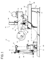
- the finishing machine 10 has a clamping device 20 for clamping a cast product and a grindstone-drive setction 50, which is provided to face the clamping device 20 and which moves a rotary grindstone towards and away from the product clamped by the clamping device 20.
- the clamping device 20 and the grindstone-drive section 50 are provided on a machine frame 12 and the whole machine is covered with a casing.
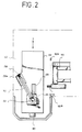
- a clamp-base 22 is movably provided on the machine frame 12 and connected to a drive unit 14.
- the clamp-base 22 can be moved in a direction inwards and outwards with respect to the paper face of the drawing of Fig. 1 and this direction is defined as X-direction (X-axis).
- a clamp-table 26 is rotatably mounted on the clamp-base 22.
- the rotational axis of the clamp-table 26 is defined as A-axis.
- a clamp-pillar 29 stands near the center of one edge section of the clamp-base 22.
- the clamp-pillar has a telescopic slidable member 29a, and a clamp-arm 30 is rotatably attached to the top end of the slidable member 29a.
- a clamp head 32 which can be rotated on the A-axis when a cast product is clamped between the clamp head 32 and the clamp-base 26, is provided at the front end of the clamp arm 30.
- the cast product clamped between the clamp-base 26 and the clamp head 32 can be rotated on the A-axis by the A-axis-motor 28.
- the grindstone-drive system 50 will be described with special reference to Figs. 3 and 4.
- a grindstone-base 52 connected to the drive unit 14 is provided on a base 51 fixed to the machine frame 12.
- Two pillars 54A and 54B are arranged, one behind the other, at the front ( at the side facing the clamping device 20) of the grindstone-base 52.
- a support-shaft 56 which can be swung back and forth, between the pillars 54A and 54B.
- the lower end of the support-shaft 56 is pivotably attached and the top end thereof can be swing towards and away from the clamping device 20.
- the support-shaft 56 has a Y-axis-motor 58 at its upper end, a ball bearing screw 59 connected to the drive shaft of the Y-axis-motor 58 and whose lower end is rotatably supported, and an elevating block 60 through which the ball bearing screw 59 is screwed and which travels up and down along the ball bearing screw 59 upon rotation of the ball bearing screw 59, with a connecting member 56a extending between the motor 58 and the lower end of the support shaft 56.
- the elevating block 60 and a shaft 62 provided at the upper end of the forward pillar 54A are connected by a second link 64.
- two projecting plates 65 face each other, and guide-bars 66 are provided in parallel to connect the plates 65
- a movable shaft 68 is mounted on the guide-bars 66.
- a driving motor 77 is mounted on the upper rear end of the first link 70.
- a belt 78 extends between and around a pulley 77a fixed at the front end of the drive shaft of the driving motor 77 and a pulley 75a of the rotary shaft 74 of the rotary grindstone 76.
- the grindstone-base 52 which is movable in the horizontal direction, perpendicular to the X-axis, is provided on the base 51.
- the moving direction of the grindstone-base 52 is defined as Z-axis.
- Two sets of supporting members extend downwardly from the front and rear ends of the grindstone-base 52 so as to support two guide-bars 81, which are arranged along both sides of the grindstone-base 52.
- the two guide-bars 81 are supported by two guide blocks 82 provided on the base 51.
- a Z-axis-motor 84 is provided in the clearance between the guide rods 81.
- the Z-axis-motor 84 is fixed on the base 51 and a screw-guide 86 is provided coaxial to the drive shaft of the motor 84.
- the screw-guide 86 is screwed through a movable block 88, which depends from the lower face of the grindstone-base 52.
- the screw-guide 86 rotates to move the movable block 88 when the Z-axis-motor 84 is driven, thereby moving the grindstone-base 52 along the guide rods 82 (see Figs. 3 and 4).
- the drive unit 14 for driving the clamp-base 22 has the same structure as the drive unit 14 of the grindstone-base 52.
- the driving motor for driving the clamp-base 22 is defined as X-axis-motor 90.
- the elevating block 60 disposed at the joint between the first link 70 and the second link 64 can be moved up and down by rotation of the ball bearing screw 59.
- the first link 70 and the second link 64 are connected, and the rear end of the first link is slidable, so that the elevating block 60 moves upward and downward when the Y-axis-motor 58 is driven, and then the front end of the rotary grindstone 76 moves vertically.
- the above described structure is a so-called Scott-Russell parallel-motion-mechanism.
- the grindstone-base 52 is moved by driving the Z-axis-motor 84 and the rotary grindstone 76 is brought into contact with the cast product M. Then the Y-axis-motor is driven to gradually move the elevating block 60 upward or downward.
- the finising machine of the present invention has control means which includes a central processing unit (CPU), a ROM in which programs and data have been stored and a RAM in which N.C. control data of removing fins on cast products will be stored.
- CPU central processing unit
- ROM read-only memory
- RAM random access memory
- This cast product M has an upper face U, a bottom face D, side faces S, a front face having an upper slope FU and a lower slope FD, and a rear face having an upper slope BU and a lower slope BD.
- a casting fin m1 along the border between the slopes FU and FD
- a casting fin m5 along the border between the slopes BU and BD.
- a teaching operation is accomplished by removing fins on the sample product M with the rotary grindstone 76 in teaching mode so as to store control data in the RAM.
- the product M is clamped by the clamping device 20.
- the X-axis-motor 90 is driven to move the clamp-base 22 to the prescribed position so as to retract the whole machine in the casing.
- the height of the contact point of the rotary grindstone 76 is adjusted by driving the Y-axis-motor 58 and the rotary grindstone is put into contact with the fin m1 by driving the Z-axis-motor 84, further the fin m1 is removed by moving the product M by driving the X-axis-motor 90.
- the rotary grindstone 76 is moved backward by driving the Z-axis-motor 84 and the clamp-base 26 is rotated on the A-axis to face the side face S toward the grindstone-drive section 50. Then, the rotary grindstone 76 is brought into contact with the fin m2 and simultaneously the product M is moved to remove the fin m2. If the rotary grindstone 76 locates above the fin m3, the movement of the product M in the Z-axis direction is stopped and the rotary grindstone 76 is lowered by driving the Y-axis-motor 58. During this process, the rotary grindstone 76 removes the fin m3 on the vertical face of the product M because of the Scott-Russell mechanism. Keeping to stop the movement in the Y-axis direction, the cast product M is moved in the X-axis direction to remove the fin m4. Then the rotary grindstone 76 is moved backward by driving the Z-axis-motor 84.
- the product M is rotated on the A-axis by driving the A-axis-motor 28 to face the rear face of the product M toward the grindstone-drive section 50.
- the rotary grindstone 76 is put into contact with the end of the fin m5 on the rear face by driving the Z-axis-motor 85 and the cast product M is moved in the X-axis direction by driving the X-axis-motor 90.
- the fin m5 is removed.
- the fins m2, m3, m5 on the other side face S are removed in the same manner as described above for the one side face S.
- the front face of the product M is faced toward the grindstone-drive section 50.
- Locations of the fins m8 and m9, which are formed to line up in the Z-axis direction and which correspond to vent holes, are made to coincide with the contact point of the rotary grindstone 76.
- the height of the contact point of the rotary grindstone 76 is made to coincide with the height of the upper face U of the product M by driving the Y-axis-motor 58.
- the fins m8 and m9 are removed by advancing the rotary grindstone 76 and then the rotary grindstone 76 is moved backward.
- clamp head 32 for pressing the upper face of the product M will have been moved upward before removing the fins m8 and m9 so as not to interrupt the removing work. If the product M is light, both side faces S and S should be clamped to keep its position; if the product is heavy, no clamping is required.
- the fins m6 and m7 corresponding to the vent holes on the slope FU of the front face will be removed.
- the fins m6 and m7, which are formed in the Z-axis direction, on the product M are moved in the X-axis direction to make their location correspond in the Z-axis direction with the contact point of the rotary grindstone 76 by driving the X-axis-motor 90.
- the height of the contact point of the rotary grindstone 76 is made to coincide with the height of the upper face U of the product M by driving the Y-axis-motor 58.
- the rotary grindstone 76 is advanced to be close to the slope FU, and then the advancement (the movement in the Z-axis direction) of the rotary grindstone 76 is stopped.
- the rotary grindstone 76 is moved along the slope FU by adjusting the rotation of the Y-axis-motor 58 and the Z-axis-motor 84 so as to remove the fins m6 and m7.
- the rotary grindstone 76 is moved back to the home position in the Y-axis and the Z-axis.
- the cast product M is moved to the take-out position by driving the X-axis-motor 90.
- control data are stored in the RAM.
- the RAM storing the data is backed up by batteries so as not to lose the data.
- the fins m1 - m9 on cast products are automatically removed by following the control program and the control data.
- the rotary grindstone 76 is itself worn away by removing fins, so that the diameter of the rotary grindstone 76 will be reduced.
- the function of detecting the amount of abrasion and correcting the movement of the rotary grindstone will be explained with reference to the flow-chart of Fig. 6.
- the program is read by CPU to start.
- the Z-axis-motor 84 is driven to define the home position of the grindstone-base 52 in the Z-axis (step 100).
- home positions thereof in the X-axis, Y-axis and Z-axis are defined (step 102).
- a sensor 92 having a light emitting section 92a and a light receiving section 92b confirms the position of the rotary grindstone 76 as a position detector (step 104). If it confirms the position, step 106 is executed.
- the coordinate system is based on the home position in the X-axis, Y-axis, Z-axis and A-axis directions (step 106).
- the height of the axis (the center) of the rotary grindstone 76 is made to coincide with the height of the sensor 92 (step 108).
- the rotary grindstone 76 is then advanced to 10mm short of the sensing position of the sensor 92 by driving the Z-axis-motor 84 (step 110).
- the grindstone-base 52 is advanced at slightly lower speed than the speed in step 110. With this advancing, the light is shut out (step 114). Then the grindstone-base 52 is moved 5mm backward (step 116). The grindstone-base 52 is advanced at slower speed (step 118), and when the rotary grindstone 76 shuts out the light from the sensor 92 the grindstone-base 52 is stopped (YES-branch of step 124). The distance in the Z-axis direction between the position at which the rotary grindstone has shut out the light and the home position thereof is defined as l.
- Fig 7 shows the relationship between the rotary grindstone 76 and the sensor 92.
- the distance between the position of the grindstone-base 52 at which the rotary grindstone 76 shuts out the light from the sensor 92 and the home position thereof is defined as L.
- the amount of abrasion h of the rotary grindstone 76 (sometimes refered to as the correction value in the following description) is stored in the RAM (step 126), and the location of the home position in the Z-axis direction is corrected to add the correction value h thereto (step 128). Further correction is also executed in the X-axis and the Y-axis directions (step 130). Then, the home position in each direction is corrected to define a new coordinate system (step 132), i.e. the correction value h is added to the home position in the X-axis and Z-axis directions so as to remove fins on the vertical side faces and the horizontal upper face (see Fig. 8). To remove fins on the slopes, however, the correction value h should be divided into the Z-axis and Y-axis directions.
- Fins on the cast product M are removed with reference to the control data in the RAM.
- the correction of the home position is executed at the start up of the machine and once every prescribed number of removing operations.
- Fig. 9(a) explains how to correct the amount of abrasion h of the rotary grindstone 76 in the Z-axis and Y-axis directions to remove fins on the slopes.
- the grindstone-base 52 should be moved the length z.
- the values z and y are corrected in the Z-axis and Y-axis directions.
- the example of removing fins on slopes by adjusting the Y-axis-motor 58 and the Z-axis-motor 84 is described, but fins on curved faces can be removed in the same manner.
- the grindstone cover 94 which covers the rotary grindstone 76 over an angle range of 90°, at the front end of the first link 70.
- the grindstone cover 94 has side plates 94a and 94a facing each other and an arc-plate 94b connecting the side plates 94a and 94a and covering circumferential faces thereof.
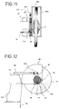
- An annular collar 72a projects from the rotary grindstone side of the bearing 72, which is provided at the front end of the first link (see Fig. 11).
- Three guide rollers 95 are provided on the side face of the grindstone cover 94.
- the guide rollers 95 are arranged around the annular collar 72a of the bearing 72 at regular intervals (see Fig. 12). Therefore, the grindstone cover 94 can be rotated on the axis of the bearing 72.
- a link plate 96 is attached to the movable shaft 68, which is provided at the rear end of the first link 70.
- the upper end of the link plate 96 and the side plate 94a of the grindstone cover 94 are connected by shafts 97a and 97b and a connecting rod 98.
- the connecting rod 98 is provided in parallel to the first link 70 (or the image line connecting the movable shaft 68 and the center of the rotary grindstone 76).
- a line r connecting the center of the rotary grindstone 76 and the shaft 97b is also vertical.
- the uppermost position of the first link 70 is shown by dotted chain lines, and the rotary grindstone in this position is indicated by symbol 76u.
- the link plate 96 is advanced (advanced link plate is indicated by symbol 96u), and the line r is vertically moved upward because of the link system, so that the orientation of the grindstone cover 94 is maintained.
- the lowermost position of the first link 70 is also shown by dotted chain lines, and the rotary grindstone in this position is indicated by symbol 76d.
- the link plate 96 is advanced with the movement of the movable shaft 60 (advanced link plate is indicated by symbol 96d), and the orientation of the grindstone cover 94 is maintained due to the link system.
- the grindstone cover 94 is not kept in its position as shown, there is a disadvantage that the front end 94c of the grindstone cover 94 may occasionally contact a projection 99 on the side face of the cast product as shown in Fig. 13 when the rotary grindstone 76 is in its lower position.
- the machine of this embodiment avoids this due to control of the position of the grindstone cover 94.
- the grindstone cover 93 can be coaxially rotated on the rotary grindstone 76 because it has a similar structure to above described grindstone cover 94.
- the link plate 96 and the grindstone cover 93 are connected by the connecting rod 98 in similar manner to above described embodiment and a cylinder unit 91 is mounted midway along the connecting rod 98.
- the exposed part of the rotary grindstone 76 can be changed by the operation of the cylinder unit 91.
- dotted chain lines show the position of the grindstone cover 93 when rotated 90 ° in anti-clockwise direction (the grindstone cover is indicated as symbol 93a; the connecting rod is indicated as symbol 98a).
- the lower part of the rotary grindstone 76 is exposed, so fins on the upper face of the cast product can be removed. It is safer to remove fins with this arrangement because the exposed part of the grindstone 76 is only directed at fins on the product.
- a rotary mechanism 102 for changing the direction (shown as dotted chain lines in Fig. 19) of the rotary grindstone 76 will now be explained.
- the clamp-base 22 can be movable in the X-direction by the X-axis-motor 90 in the same manner as in the former embodiment.
- the grindstone-base 52 is movable in the horizontal Z-direction perpendicular to the X-direction.
- the grindstone-drive section 50 is mounted on the grindstone-base 52 parallel to the Z-direction in the same manner as in the former embodiment.
- the rotary mechanism 102 is provided at the front end of the first link 70.
- Respective bearings 104 are provided at the front ends of the side plates 70a and 70b.
- a rotary shaft 106 is rotatably supported by the bearings 104.
- the driving motor 77 is mounted on the fixed plate 108a.
- On the fixed plate 108b a bearing rotatably supporting the rotary shaft 74 of the rotary grindstone 76 is mounted.
- the grindstone cover 94 covering the rotary grindstone 76 is fixed to the fixed plate 108b coaxial to the rotary shaft 74.
- Belts 78 engage around a pulley 77a which is fixed at the front end of the drive shaft of the motor 77 and a pulley 75a which is mounted on the rotary shaft 74 of the rotary grindstone 76.
- the pulleys 77a and 75a and the belts 78 are covered by a belt-cover 112, which is fixed to the fixed plates 108a and 108b (see Fig. 16).
- a gear box 114 is provided midway along the rotary shaft 106, and a gear 116 is fixed on the rotary shaft 106 in the gear box 114.
- a motor 118 is fixed on the upper face of the gear box 114, and a worm gear 120, which engages with the gear 116 on the rotary shaft 106, is fixed on a shaft 118a, which transmits rotary force from the motor 118 (see Fig. 16).
- Supporting arms 122 extended upwardly in parallel to the rotary shaft 106 from the both side faces of the gear box 114 (see Fig. 18).
- Supporting members 124 are mounted on the movable shaft 68, which is provided at the rear end of the first link 70.
- the supporting members 124 and the supporting arms 122 are pivotably attached to respective connecting plates 126.
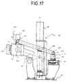
- a parallel link system is formed by the connecting plate 126, the first link 70 and the links e and f.
- the gear box 114 always keeps its position vertical because the links e and f always kept their position vertical when the front end of the first link 70 is moved up and down.
- the rotary shaft 106 is rotated by the mechanism including the worm gear 120 on the shaft 118a and the gear 116 engaging with the worm gear 120, and the rotary grindstone 76 is rotated on the rotary shaft 106.
- the rotary grindstone 76 can change its position from horizontal to a variety of inclined positions as shown by dotted chain lines in Fig. 19.
- the rotary mechanism 102 is provided at the front end of the first link 70, so that fins in the concave section 100 of the cast product M can be. removed.
Landscapes
- Engineering & Computer Science (AREA)
- Mechanical Engineering (AREA)
- Grinding And Polishing Of Tertiary Curved Surfaces And Surfaces With Complex Shapes (AREA)
- Finish Polishing, Edge Sharpening, And Grinding By Specific Grinding Devices (AREA)
Description
- The present invention relates to a finishing machine for cast products, which removes fins and unnecessary parts.
- As shown in Fig. 20, casting is executed by pouring molten metal into a gate of a mold from a ladle. The mold is composed of a combination of an upper mold and a lower mold. Therefore, molten metal gets into the gap between the lower mold 1a and the upper mold 1b, so that casting fins are formed in the gap. Further, the mold also has a gate 9a for pouring molten metal therein,
gas vents 9b for letting out gas in the molten metal and afeeder head 9c for pouring additional molten metal into product section in which molten metal contracts when it is cooled. With this structure of mold, cast products have unnecessary parts, i.e. fins are formed to correspond to the gate, the gas vents and the feeder head. Further, core-fins are sometimes formed on the product when a core is set in the mold. Therefore, the product has casting fins, core-fins and unnecessary parts cast (they will be described as "fins" in the following description). The fins should be removed in following manufacturing process. - Conventionally, the fins are removed by pressing a cast product on to a circumferential face of a rotary grinder.
- There exists a finishing machine, shown in Fig. 21, for removing fins on cast products. In the finishing machine, a
rotary grindstone 2 driven by amotor 3 is moved close to a cast product 4, which is clamped by clamping means, so as to remove fins on the product 4. The vertical position of the rotary grindstone with respect to the product 4 is controlled by vertical movement of a table 7, which is moved by rotation of a ball bearing screw driven by a servo motor 5. Therotary grindstone 2 can be also moved to words and away from the product 4 on the table 7 by acylinder unit 8. - However, it is dangerous to manually grind the product by the rotary grinder because there is a risk that a worker touches the grinder and gets injured.
- It is preferable for removing fins on the circumferential face of the product to use the finishing machine but the machine cannot remove fins on the upper and sloping faces thereof. To remove fins on these faces, the position of the clamped product should be changed. The
rotary grindstone 2 is worn down by removing fins on the product. Once it is worn, the rotary grindstone cannot perfectly remove fins even it is controlled by an N.C. control system. - A system is disclosed in Patent Abstracts of Japan, Vol. 12, No. 169 (M-699) (3016) of compensating for wear of a grindstone by moving said grindstone until its presence is detected by a sensor, and storing data on the orientations of the apparatus parts supporting the grinder in this position as the latter is successively worn down so that in subsequent operations the wear can be compensated for by using the same sequence of orientations.
- The object of the present invention is to provide a finishing machine for cast products in which the movement of the rotary grindstone can be corrected according to the amount of abrasion of the rotary grindstone so as to perfectly remove fins on the upper and circumferential faces of the cast products.
- To achieve the object, the present invention provides a finishing machine for cast products comprising:
a rotary grindstone for removing fins etc. from a work piece;
a clamp-base movable in a horizontal X-direction;
a clamping device, provided on the clamp-base, for clamping the work piece and rotatable on an A-axis perpendicular to the X-direction;
a grindstone base movable in a horizontal Z-direction perpendicular to the X-direction so as to move towards and away from the clamp-base;
a support shaft having one end pivotably attached to the grindstone-base so as to be swingable in a vertical plane;
an elevating block which is movable on the support-shaft;
a link having one end pivotably attached to the elevating block and its other end pivotably attached to the grind-stone base, said one end being movable on said support-shaft by the movement of the elevating block;
a swing arm pivotably attached to the elevating block in a central region thereof so as to be swingable in a vertical plane, the rear end of the swing arm being movable along a guide and the rotary grindstone, which rotates on a rotary shaft arranged in the X-direction and which is movable in the Y-direction by the movement of the elevating block, being provided at the front end of the swing arm;
means for controlling drive units of the clamp-base, the clamping device, the grindstone-base and the elevating block so as to remove fins, etc. produced on an upper face and/or circumferencial faces of the piece;
means for detecting the amount of abrasion of the rotary grindstone; and
means for correcting the distance of travel of the grindstone base and/or the elevating block corresponding to the amount of abrasion of the rotary grindstone. - There are two basic constructions of machine. In the first, the support shaft is swingable in a vertical plane perpendicular to the X-direction, and the swing arm is also swingable in a vertical plane perpendicular to the X-direction with its rear end being movable along the guide in the Z-direction.
- In the second, the support shaft is swingable in a vertical plane parallel to the X-direction; and the swing arm is also swingable in a vertical plane parallel to the X-direction with its rear end being movable along the guide in the X-direction.
- Further, preferably, the means for correcting adds the amount of abrasion of the rotary grindstone to the distance of travel of the rotary grindstone in the Z-direction when fins, etc. on the face parallel to the A-axis are removed,
the means for correcting adds the amount of abrasion to the distance of travel of the rotary grindstone in the Y-direction when fins, etc. on the upper face parallel to the clamp-base are removed, and
the means for correcting divides the amount of abrasion to add to each of the distances of travel of the rotary grindstone in the Z-direction and Y-direction when fins, etc. on sloping and curved faces are removed. - The machine may further comprise a grindstone cover partially covering the rotary grindstone, i.e. one part is exposed therefrom, the grindstone cover being coaxial to the rotary grindstone and rotatable, and
means for controlling the position of the grindstone cover to face the exposed part of the rotary grindstone to a face of the workpiece on which fins, etc. are present. - A bearing for rotatably supporting the rotary grindstone and a motor for driving the rotary grindstone may be mounted at respective ends of a rotary shaft, which can be rotated on an axis in the Z-direction and which is mounted at the front end of the swing arm.
- When the rotary grindstone wears, the means for detecting detects the amount of abrasion, and the means for correcting adds the amount of abrasion to the distance of travel of the rotary grindstone, so that fins are perfectly removed.
- Further, a finishing machine having the rotary mechanism can rotationally change the direction of the rotary grindstone.
- With above described structures and functions, the finishing machine of the present invention has following advantages:
- (a) Once a cast product is set, fins on side faces, upper face, slope faces and curved faces can be removed without changing the position of the cast product.
- (b) Uniform finishing work can be executed because the amount of abrasion of the rotary grindstone is detected and the means for correcting adds the amount of abrasion to the amount of travelling of the rotary grindstone so as to correct the movement of the rotary grindstone.
- (c) Removing work can be executed more safely because the exposed part of the rotary grindstone can be directed to faces of the cast product, on which fins have been produced, by the means for controlling the position of the grindstone cover.
- With the rotary mechanism, fins in concave sections of the cast product can be removed.
- Further objects and advantages of the present invention will be apparent from the following description, reference being had to the accompanying drawings wherein preferred embodiments of the present invention are clearly shown.
- In the drawings:
- Fig. 1 shows a schematic front view of the finishing machine for cast products of the present invention;
- Fig. 2 shows a plan view of a clamping device;
- Fig. 3 shows a front view of a grindstone-drive section;
- Fig. 4 shows a plan view of a grindstone-drive section;
- Fig. 5 shows a perspective view of a casted product;
- Fig. 6 shows a flow-chart for correcting the movement of the rotary grindstone;
- Fig. 7 shows an explanation view of the rotary grindstone and a sensor;
- Fig. 8 shows a side view of the cast product;
- Fig. 9 shows an explanation view showing the correction for removing fins on a slope face;
- Fig. 10 shows a front view of the means for controlling the position of the grindstone cover;
- Fig. 11 shows a partial side view of the grindstone cover attached;
- Fig. 12 shows a rear view of the grindstone cover attached;
- Fig. 13 shows an explanation view of the rotary grindstone descended;
- Fig. 14 shows a front view of the means for controlling the grindstone-drive section;
- Fig. 15 shows a schematic plan view of the finishing machine having a rotary mechanism;
- Fig. 16 shows a partial sectional plan view of the rotary mechanism;
- Fig. 17 shows a schematic front view of the grindstone-drive section;
- Fig. 18 shows a schematic side view of the grindstone-drive section in the direction from the rotary mechanism;
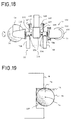
- Fig. 19 shows an explanation view of the cast product and the rotary grindstone;
- Fig. 20 shows a longitudinal sectional view of a mold; and
- Fig. 21 shows a side view of a conventional finishing machine.
- A preferred embodiment of the present invention will now be described in detail.
- With reference to Figs. 1 to 4, the finishing machine 10 has a
clamping device 20 for clamping a cast product and a grindstone-drive setction 50, which is provided to face theclamping device 20 and which moves a rotary grindstone towards and away from the product clamped by the clampingdevice 20. The clampingdevice 20 and the grindstone-drive section 50 are provided on amachine frame 12 and the whole machine is covered with a casing. - First, the clamping
device 20 will be explained. - A clamp-
base 22 is movably provided on themachine frame 12 and connected to adrive unit 14. The clamp-base 22 can be moved in a direction inwards and outwards with respect to the paper face of the drawing of Fig. 1 and this direction is defined as X-direction (X-axis). A clamp-table 26 is rotatably mounted on the clamp-base 22. The rotational axis of the clamp-table 26 is defined as A-axis. There is provided an A-axis-motor 28 for rotating the clamp-table 26 on the A-axis. (see Fig. 2). - A clamp-
pillar 29 stands near the center of one edge section of the clamp-base 22. The clamp-pillar has a telescopicslidable member 29a, and a clamp-arm 30 is rotatably attached to the top end of theslidable member 29a. Aclamp head 32, which can be rotated on the A-axis when a cast product is clamped between theclamp head 32 and the clamp-base 26, is provided at the front end of theclamp arm 30. Thus, the cast product clamped between the clamp-base 26 and theclamp head 32 can be rotated on the A-axis by the A-axis-motor 28. - The grindstone-
drive system 50 will be described with special reference to Figs. 3 and 4. - A grindstone-
base 52 connected to thedrive unit 14 is provided on a base 51 fixed to themachine frame 12. - Two
pillars base 52. There is swingably provided a support-shaft 56, which can be swung back and forth, between thepillars shaft 56 is pivotably attached and the top end thereof can be swing towards and away from the clampingdevice 20. The support-shaft 56 has a Y-axis-motor 58 at its upper end, a ball bearing screw 59 connected to the drive shaft of the Y-axis-motor 58 and whose lower end is rotatably supported, and an elevatingblock 60 through which theball bearing screw 59 is screwed and which travels up and down along theball bearing screw 59 upon rotation of theball bearing screw 59, with a connectingmember 56a extending between themotor 58 and the lower end of thesupport shaft 56. The elevatingblock 60 and ashaft 62 provided at the upper end of theforward pillar 54A are connected by asecond link 64. - On the upper face of the
pillar 54B, two projectingplates 65 face each other, and guide-bars 66 are provided in parallel to connect the plates 65 Amovable shaft 68 is mounted on the guide-bars 66. - Contact and rear sections of two
side plates block 60 and to respective ends of themovable shaft 68. Theseside plates first link 70 in the form of a swing arm.Bearings 72 of therotary grindstone 76 are fixed at the front end of thefirst link 70. Arotary shaft 74, which is rotatably supported by thebearings 72, projects at both ends from thebearings 72. Therotary grindstone 76 is fixed at one end of therotary shaft 74 and apulley 74a is fixed at the other end thereof. - A driving
motor 77 is mounted on the upper rear end of thefirst link 70. Abelt 78 extends between and around apulley 77a fixed at the front end of the drive shaft of the drivingmotor 77 and apulley 75a of therotary shaft 74 of therotary grindstone 76. - The drive unit of the grindstone-
base 52 will now be explained. - The grindstone-
base 52, which is movable in the horizontal direction, perpendicular to the X-axis, is provided on thebase 51. The moving direction of the grindstone-base 52 is defined as Z-axis. - Two sets of supporting members extend downwardly from the front and rear ends of the grindstone-
base 52 so as to support two guide-bars 81, which are arranged along both sides of the grindstone-base 52. The two guide-bars 81 are supported by two guide blocks 82 provided on thebase 51. - A Z-axis-
motor 84 is provided in the clearance between theguide rods 81. The Z-axis-motor 84 is fixed on thebase 51 and a screw-guide 86 is provided coaxial to the drive shaft of themotor 84. The screw-guide 86 is screwed through amovable block 88, which depends from the lower face of the grindstone-base 52. - Therefore, the screw-
guide 86 rotates to move themovable block 88 when the Z-axis-motor 84 is driven, thereby moving the grindstone-base 52 along the guide rods 82 (see Figs. 3 and 4). - The
drive unit 14 for driving the clamp-base 22 has the same structure as thedrive unit 14 of the grindstone-base 52. However the driving motor for driving the clamp-base 22 is defined as X-axis-motor 90. - The elevating
block 60 disposed at the joint between thefirst link 70 and thesecond link 64 can be moved up and down by rotation of theball bearing screw 59. Thefirst link 70 and thesecond link 64 are connected, and the rear end of the first link is slidable, so that the elevatingblock 60 moves upward and downward when the Y-axis-motor 58 is driven, and then the front end of therotary grindstone 76 moves vertically. The above described structure is a so-called Scott-Russell parallel-motion-mechanism. The relationship between the length P (the distance between therotary shaft 74 of therotary grindstone 76 and the elevating block 60), the length B (the distance between the elevatingblock 60 and the movable shaft 68), and the length G (the distance between the elevatingblock 60 and the shaft 62) will be:
and themovable shaft 68 and theshaft 62 are set horizontally. - Movement of the finishing machine for removing fins will now be explained.
- To remove fins on a vertical face of a cast product M, the grindstone-
base 52 is moved by driving the Z-axis-motor 84 and therotary grindstone 76 is brought into contact with the cast product M. Then the Y-axis-motor is driven to gradually move the elevatingblock 60 upward or downward. - While removing fins on cast products M, the diameter of the
rotary grindstone 76 is gradually reduced due to abrasion. Therefore, fins on the cast product M cannot be perfectly removed with the prescribed movement of therotary grindstone 76. - Then, correcting the amount of travelling of the
rotary grindstone 76 in the Z-direction by the amount of abrasion of therotary grindstone 76 reinstates proper removed of fins. Therefore, it is suitable to measure the amount of abrasion of therotary grindstone 76 at the start of the machine or once every prescibed number of operations. - The finising machine of the present invention has control means which includes a central processing unit (CPU), a ROM in which programs and data have been stored and a RAM in which N.C. control data of removing fins on cast products will be stored.
- Now, the case of the cast product shown in Fig. 5 will be explained. This cast product M has an upper face U, a bottom face D, side faces S, a front face having an upper slope FU and a lower slope FD, and a rear face having an upper slope BU and a lower slope BD. There are formed a casting fin m₁ along the border between the slopes FU and FD, crank-shaped casting fins m₂, m₃ and m₄ on both side faces, and a casting fin m₅ along the border between the slopes BU and BD. There also are unnecessary parts m₆, m₇, m₈ and m₉ corresponding to gas vent holes on the upper face U and the slope FD.
- First, a teaching operation is accomplished by removing fins on the sample product M with the
rotary grindstone 76 in teaching mode so as to store control data in the RAM. - Next, the steps of the teaching will be explained.
- The product M is clamped by the clamping
device 20. The X-axis-motor 90 is driven to move the clamp-base 22 to the prescribed position so as to retract the whole machine in the casing. In this state, the height of the contact point of therotary grindstone 76 is adjusted by driving the Y-axis-motor 58 and the rotary grindstone is put into contact with the fin m₁ by driving the Z-axis-motor 84, further the fin m₁ is removed by moving the product M by driving the X-axis-motor 90. - Next, the
rotary grindstone 76 is moved backward by driving the Z-axis-motor 84 and the clamp-base 26 is rotated on the A-axis to face the side face S toward the grindstone-drive section 50. Then, therotary grindstone 76 is brought into contact with the fin m₂ and simultaneously the product M is moved to remove the fin m₂. If therotary grindstone 76 locates above the fin m₃, the movement of the product M in the Z-axis direction is stopped and therotary grindstone 76 is lowered by driving the Y-axis-motor 58. During this process, therotary grindstone 76 removes the fin m₃ on the vertical face of the product M because of the Scott-Russell mechanism. Keeping to stop the movement in the Y-axis direction, the cast product M is moved in the X-axis direction to remove the fin m₄. Then therotary grindstone 76 is moved backward by driving the Z-axis-motor 84. - The product M is rotated on the A-axis by driving the A-axis-
motor 28 to face the rear face of the product M toward the grindstone-drive section 50. Therotary grindstone 76 is put into contact with the end of the fin m₅ on the rear face by driving the Z-axis-motor 85 and the cast product M is moved in the X-axis direction by driving the X-axis-motor 90. The fin m₅ is removed. - Successively, the fins m₂, m₃, m₅ on the other side face S are removed in the same manner as described above for the one side face S.
- Next, the front face of the product M is faced toward the grindstone-
drive section 50. Locations of the fins m₈ and m₉, which are formed to line up in the Z-axis direction and which correspond to vent holes, are made to coincide with the contact point of therotary grindstone 76. In other words, the height of the contact point of therotary grindstone 76 is made to coincide with the height of the upper face U of the product M by driving the Y-axis-motor 58. The fins m₈ and m₉ are removed by advancing therotary grindstone 76 and then therotary grindstone 76 is moved backward. Note that theclamp head 32 for pressing the upper face of the product M will have been moved upward before removing the fins m₈ and m₉ so as not to interrupt the removing work. If the product M is light, both side faces S and S should be clamped to keep its position; if the product is heavy, no clamping is required. - Next, the fins m₆ and m₇ corresponding to the vent holes on the slope FU of the front face will be removed. First, the fins m₆ and m₇, which are formed in the Z-axis direction, on the product M are moved in the X-axis direction to make their location correspond in the Z-axis direction with the contact point of the
rotary grindstone 76 by driving the X-axis-motor 90. The height of the contact point of therotary grindstone 76 is made to coincide with the height of the upper face U of the product M by driving the Y-axis-motor 58. Therotary grindstone 76 is advanced to be close to the slope FU, and then the advancement (the movement in the Z-axis direction) of therotary grindstone 76 is stopped. Therotary grindstone 76 is moved along the slope FU by adjusting the rotation of the Y-axis-motor 58 and the Z-axis-motor 84 so as to remove the fins m₆ and m₇. - After use, the
rotary grindstone 76 is moved back to the home position in the Y-axis and the Z-axis. - The cast product M is moved to the take-out position by driving the X-axis-
motor 90. - The teaching is executed as described above, and control data are stored in the RAM. The RAM storing the data is backed up by batteries so as not to lose the data.
- In the working mode, the fins m₁ - m₉ on cast products are automatically removed by following the control program and the control data.
- As described above, the
rotary grindstone 76 is itself worn away by removing fins, so that the diameter of therotary grindstone 76 will be reduced. The function of detecting the amount of abrasion and correcting the movement of the rotary grindstone will be explained with reference to the flow-chart of Fig. 6. - Upon turning on the machine, the program is read by CPU to start. First, the Z-axis-
motor 84 is driven to define the home position of the grindstone-base 52 in the Z-axis (step 100). Successively, home positions thereof in the X-axis, Y-axis and Z-axis are defined (step 102). - A
sensor 92 having alight emitting section 92a and alight receiving section 92b (see Figs. 2 and 4) confirms the position of therotary grindstone 76 as a position detector (step 104). If it confirms the position,step 106 is executed. - The coordinate system is based on the home position in the X-axis, Y-axis, Z-axis and A-axis directions (step 106).
- The height of the axis (the center) of the
rotary grindstone 76 is made to coincide with the height of the sensor 92 (step 108). - The
rotary grindstone 76 is then advanced to 10mm short of the sensing position of thesensor 92 by driving the Z-axis-motor 84 (step 110). - Next, the grindstone-
base 52 is advanced at slightly lower speed than the speed instep 110. With this advancing, the light is shut out (step 114). Then the grindstone-base 52 is moved 5mm backward (step 116). The grindstone-base 52 is advanced at slower speed (step 118), and when therotary grindstone 76 shuts out the light from thesensor 92 the grindstone-base 52 is stopped (YES-branch of step 124). The distance in the Z-axis direction between the position at which the rotary grindstone has shut out the light and the home position thereof is defined as ℓ. - Fig 7 shows the relationship between the
rotary grindstone 76 and thesensor 92. During the teaching mode, the distance between the position of the grindstone-base 52 at which therotary grindstone 76 shuts out the light from thesensor 92 and the home position thereof is defined as L. In this case, the amount of abrasion h of therotary grindstone 76 is:
- The amount of abrasion h of the rotary grindstone 76 (sometimes refered to as the correction value in the following description) is stored in the RAM (step 126), and the location of the home position in the Z-axis direction is corrected to add the correction value h thereto (step 128). Further correction is also executed in the X-axis and the Y-axis directions (step 130). Then, the home position in each direction is corrected to define a new coordinate system (step 132), i.e. the correction value h is added to the home position in the X-axis and Z-axis directions so as to remove fins on the vertical side faces and the horizontal upper face (see Fig. 8). To remove fins on the slopes, however, the correction value h should be divided into the Z-axis and Y-axis directions.
- Fins on the cast product M are removed with reference to the control data in the RAM. Preferably, the correction of the home position is executed at the start up of the machine and once every prescribed number of removing operations.
- Fig. 9(a) explains how to correct the amount of abrasion h of the
rotary grindstone 76 in the Z-axis and Y-axis directions to remove fins on the slopes. - The correction value z, in the Z-direction, of the amount of abrasion h of the
rotary grindstone 76 is:
- To correct the amount z , the grindstone-
base 52 should be moved the length z. - The correction value y, in the Y-direction thereof, is:

- In this case, the distance y₁ of travelling of the elevating
block 60, which travels on theball bearing screw 59 driven by the Y-axis-motor 58 is:
- The value d will be explained with reference to Fig. 9(b). If the distance of travel of the elevating
block 60 on theball bearing screw 59 driven by the Y-axis-motor 58 is defined as e and the distance of travel of therotary grindstone 76 is defined as H, the values have following relationship;
and
- The values H and e are proportion at to each other.
- In case of slopes, the values z and y are corrected in the Z-axis and Y-axis directions. The example of removing fins on slopes by adjusting the Y-axis-
motor 58 and the Z-axis-motor 84 is described, but fins on curved faces can be removed in the same manner. - Next, preferred means for controlling the position of a grindstone cover of the machine will be explained with reference to Figs. 10-12.
- There is a
grindstone cover 94, which covers therotary grindstone 76 over an angle range of 90°, at the front end of thefirst link 70. Thegrindstone cover 94 hasside plates plate 94b connecting theside plates - An
annular collar 72a projects from the rotary grindstone side of thebearing 72, which is provided at the front end of the first link (see Fig. 11). Threeguide rollers 95, each of which has a groove, which fits onto theannular collar 72a, are provided on the side face of thegrindstone cover 94. Theguide rollers 95 are arranged around theannular collar 72a of thebearing 72 at regular intervals (see Fig. 12). Therefore, thegrindstone cover 94 can be rotated on the axis of thebearing 72. - A
link plate 96 is attached to themovable shaft 68, which is provided at the rear end of thefirst link 70. The upper end of thelink plate 96 and theside plate 94a of thegrindstone cover 94 are connected byshafts rod 98. The connectingrod 98 is provided in parallel to the first link 70 (or the image line connecting themovable shaft 68 and the center of the rotary grindstone 76). A line r connecting the center of therotary grindstone 76 and theshaft 97b is also vertical. - The uppermost position of the
first link 70 is shown by dotted chain lines, and the rotary grindstone in this position is indicated by symbol 76u. In this state, thelink plate 96 is advanced (advanced link plate is indicated bysymbol 96u), and the line r is vertically moved upward because of the link system, so that the orientation of thegrindstone cover 94 is maintained. - Similarly, the lowermost position of the
first link 70 is also shown by dotted chain lines, and the rotary grindstone in this position is indicated bysymbol 76d. In this state, thelink plate 96 is advanced with the movement of the movable shaft 60 (advanced link plate is indicated bysymbol 96d), and the orientation of thegrindstone cover 94 is maintained due to the link system. - If the
grindstone cover 94 is not kept in its position as shown, there is a disadvantage that the front end 94c of thegrindstone cover 94 may occasionally contact aprojection 99 on the side face of the cast product as shown in Fig. 13 when therotary grindstone 76 is in its lower position. The machine of this embodiment avoids this due to control of the position of thegrindstone cover 94. - Means for controlling the position of another
grindstone cover 93, which exposes a third of thegrindstone 76, will be explained with reference to Fig. 14. - The grindstone cover 93 can be coaxially rotated on the
rotary grindstone 76 because it has a similar structure to above describedgrindstone cover 94. - The
link plate 96 and thegrindstone cover 93 are connected by the connectingrod 98 in similar manner to above described embodiment and acylinder unit 91 is mounted midway along the connectingrod 98. The exposed part of therotary grindstone 76 can be changed by the operation of thecylinder unit 91. - In Fig. 14, dotted chain lines show the position of the
grindstone cover 93 when rotated 90 ° in anti-clockwise direction (the grindstone cover is indicated assymbol 93a; the connecting rod is indicated assymbol 98a). In this case, the lower part of therotary grindstone 76 is exposed, so fins on the upper face of the cast product can be removed. It is safer to remove fins with this arrangement because the exposed part of thegrindstone 76 is only directed at fins on the product. - With this means for controlling the position of the
grindstone cover 93, suitable control can be executed without interrupting fin-removing work by driving the link system and thecylinder unit 91. In other embodiments thecylinder unit 91 may be omitted. - With the finishing machine of this embodiment, fins in a
concave section 100 of the product M cannot be removed in cases where therotary grindstone 76 has to move close into theconcave section 100 of the product M (see Fig. 19). - A
rotary mechanism 102 for changing the direction (shown as dotted chain lines in Fig. 19) of therotary grindstone 76 will now be explained. - In Fig. 15, the clamp-
base 22 can be movable in the X-direction by the X-axis-motor 90 in the same manner as in the former embodiment. The grindstone-base 52 is movable in the horizontal Z-direction perpendicular to the X-direction. The grindstone-drive section 50 is mounted on the grindstone-base 52 parallel to the Z-direction in the same manner as in the former embodiment. Therotary mechanism 102 is provided at the front end of thefirst link 70. - The rotary mechanism will be described with reference to Figs. 15-18.
-
Respective bearings 104 are provided at the front ends of theside plates rotary shaft 106 is rotatably supported by thebearings 104. There are respective fixedplates rotary shaft 106. On the fixedplate 108a, the drivingmotor 77 is mounted. On the fixedplate 108b a bearing rotatably supporting therotary shaft 74 of therotary grindstone 76 is mounted. The grindstone cover 94 covering therotary grindstone 76 is fixed to the fixedplate 108b coaxial to therotary shaft 74.Belts 78 engage around apulley 77a which is fixed at the front end of the drive shaft of themotor 77 and apulley 75a which is mounted on therotary shaft 74 of therotary grindstone 76. Thepulleys belts 78 are covered by a belt-cover 112, which is fixed to the fixedplates - With this structure, the
rotary grindstone 76 and themotor 77, etc., which are fixed on the fixedplates rotary shaft 106. Agear box 114 is provided midway along therotary shaft 106, and agear 116 is fixed on therotary shaft 106 in thegear box 114. Amotor 118 is fixed on the upper face of thegear box 114, and aworm gear 120, which engages with thegear 116 on therotary shaft 106, is fixed on ashaft 118a, which transmits rotary force from the motor 118 (see Fig. 16). Supportingarms 122 extended upwardly in parallel to therotary shaft 106 from the both side faces of the gear box 114 (see Fig. 18). Supportingmembers 124 are mounted on themovable shaft 68, which is provided at the rear end of thefirst link 70. The supportingmembers 124 and the supportingarms 122 are pivotably attached to respective connectingplates 126. - As shown in Fig. 17, a
shaft 127 to which the supportingarm 122 and the connectingplate 126 are pivotably attached and therotary shaft 106 maintain their vertical relationship and a vertical link is defined as e. A link f, which connects a shaft to which the supportingmember 124 and the connectingplate 126 are pivotably attached and themovable shaft 68, is also kept vertical. - With this structure, a parallel link system is formed by the connecting
plate 126, thefirst link 70 and the links e and f. Thegear box 114 always keeps its position vertical because the links e and f always kept their position vertical when the front end of thefirst link 70 is moved up and down. - When the
motor 118 is driven, therotary shaft 106 is rotated by the mechanism including theworm gear 120 on theshaft 118a and thegear 116 engaging with theworm gear 120, and therotary grindstone 76 is rotated on therotary shaft 106. Therotary grindstone 76 can change its position from horizontal to a variety of inclined positions as shown by dotted chain lines in Fig. 19. - In this embodiment, the
rotary mechanism 102 is provided at the front end of thefirst link 70, so that fins in theconcave section 100 of the cast product M can be. removed. - Preferred embodiments of the present invention have been described as above but the present invention is not limited to the above embodiments. Many modifications are possible without deviating from the scope of claims.
Claims (5)
- A finishing machine (10) for cast products comprising:
a rotary grindstone (76) for removing fins etc. from a work piece (M);
a clamp-base (22) movable in a horizontal X-direction;
a clamping device (20), provided on the clamp-base (22), for clamping the work piece (M) and rotatable on an A-axis perpendicular to the X-direction;
a grindstone base (52) movable in a horizontal Z-direction perpendicular to the X-direction so as to move towards and away from the clamp-base (22);
a support shaft (56) having one end pivotably attached to the grindstone-base (52) so as to be swingable in a vertical plane perpendicular to the X-direction;
an elevating block (60) which is movable on the support-shaft (56);
a link (64) having one end pivotably attached to the elevating block (60) and its other end pivotably attached to the grindstone base (52), said one end being movable on said support shaft (56) by the movement of the elevating block (60);
a swing arm (70) pivotably attached to the elevating block (60) in a central region thereof so as to be swingable in a vertical plane perpendicular to the X-direction, the rear end of the swing arm (70) being movable along a guide (66) in the Z-direction and the rotary grindstone (76), which rotates on a rotary shaft (74) arranged in the X-direction and which is movable in the Y-direction by the movement of the elevating block (60), being provided at the front end of the swing arm (70);
means for controlling driving units of the clamp-base (22), the clamping device (20), the grindstone base (52) and the elevating block (60) so as to remove fins, etc. produced on an upper face and/or circumferencial faces of the work piece (M);
means for detecting the amount (h) of abrasion of the rotary grindstone (76); and
means for correcting the distance of travel of the grindstone base (76) and/or the elevating block (60) corresponding to the amount (h) of abrasion of the rotary grindstone (76). - A finishing machine (10) for cast products comprising:
a rotary grindstone (76) for removing fins etc. from a work piece (M);
a clamp-base (22) movable in a horizontal X-direction;
a clamping device (20), provided on the clamp-base (22), for clamping the work piece (M) and rotatable on an A-axis perpendicular to the X-direction;
a grindstone base (52) movable in a horizontal Z-direction perpendicular to the X-direction so as to move towards and away from the clamp-base (22);
a support shaft (56) having one end pivotably attached to the grindstone-base (52) so as to be swingable in a vertical plane parallel to the X-direction;
an elevating block (60) which is movable on the support-shaft (56);
a link (64) having one end pivotably attached to the elevating block (60) and is other end pivotably attached to the grindstone base (52), said one end being movable on said support shaft (56) by the movement of the elevating block (60);
a swing arm (70) pivotably attached to the elevating block (60) in a central region thereof so as to be swingable in a vertical plane parallel to the X-direction, the rear end of the swing arm (70) being movable along a guide (66) in the X-direction and the rotary grindstone (76), which rotates on a rotary shaft (74) arranged in the X-direction and which is movable in the Y-direction by the movement of the elevating block (60), being provided at the front end of the swing arm (70);
means for controlling driving units of the clamp-base (22), the clamping device (20), the grindstone base (52) and the elevating block (60) so as to remove fins, etc. produced on an upper face and/or circumferencial faces of the work piece (M);
means for detecting the amount (h) of abrasion of the rotary grindstone (76); and
means for correcting the distance of travel of the grindstone base (76) and/or the elevating block (60) corresponding to the amount (h) of abrasion of the rotary grindstone (76). - A finishing machine for cast products according to claim 1 or 2, wherein:
the means for correcting adds the amount (h) of abrasion of the rotary grindstone (76) to the distance of travel of the rotary grindstone (76) in the Z-direction when fins, etc. on the face parallel to the A-axis are removed;
the means for correcting adds the amount (h) of abrasion to the distance of travel of the rotary grindstone (76) in the Y-direction when fins, etc. on the upper face parallel to the clamp-base (22) are removed; and
the means for correcting divides the amount (h) of abrasion to add to each of the distances of travel of the rotary grindstone (76) in the Z-direction and the Y-direction when fins, etc. on sloping and curved faces are removed. - A finishing machine for cast products according to claim 1, further comprising:
a grindstone cover (94) partially covering said rotary grindstone (76), said cover (94) being coaxial to the rotary grindstone (76) and rotatable; and
means for controlling the position of the grindstone cover (94) to face the exposed part of the rotary grindstone (76) towards a surface of the work piece (M) on which fins, etc. are present. - A finishing machine for cast products according to claim 2, wherein a bearing (110) rotatably supporting the rotary grindstone (76) and a motor (77) for driving said rotary grindstone (76) are mounted at respective ends of a rotary shaft (106), which is mounted at the front end of the swing arm (70) and is rotatable on an axis arranged in the Z-direction.
Applications Claiming Priority (2)
| Application Number | Priority Date | Filing Date | Title |
|---|---|---|---|
| JP101195/89 | 1989-04-20 | ||
| JP1101195A JPH02280957A (en) | 1989-04-20 | 1989-04-20 | Apparatus for finishing casting product |
Publications (3)
| Publication Number | Publication Date |
|---|---|
| EP0394040A2 EP0394040A2 (en) | 1990-10-24 |
| EP0394040A3 EP0394040A3 (en) | 1990-12-12 |
| EP0394040B1 true EP0394040B1 (en) | 1994-03-23 |
Family
ID=14294166
Family Applications (1)
| Application Number | Title | Priority Date | Filing Date |
|---|---|---|---|
| EP90304216A Expired - Lifetime EP0394040B1 (en) | 1989-04-20 | 1990-04-19 | A finishing machine for casted products |
Country Status (4)
| Country | Link |
|---|---|
| US (1) | US5044124A (en) |
| EP (1) | EP0394040B1 (en) |
| JP (1) | JPH02280957A (en) |
| DE (1) | DE69007524T2 (en) |
Families Citing this family (20)
| Publication number | Priority date | Publication date | Assignee | Title |
|---|---|---|---|---|
| US5934975A (en) * | 1987-09-04 | 1999-08-10 | Svanberg; Gunnar K. | Dental curet and sharpening machine system |
| US5645468A (en) * | 1987-09-04 | 1997-07-08 | Svanberg; Gunnar K. | Dental curet and sharpening machine system |
| FR2680477B1 (en) * | 1991-08-22 | 1995-12-08 | Pont A Mousson | TRIMMING PROCESS AND MACHINE. |
| US5209021A (en) * | 1991-08-30 | 1993-05-11 | Amsted Industries, Inc. | Apparatus and method for sprue removal and grinding of railroad wheels |
| US5441437A (en) * | 1993-02-18 | 1995-08-15 | Hulstedt; Bryan A. | Compliant constant-force follower device for surface finishing tool |
| CN1055884C (en) * | 1993-12-16 | 2000-08-30 | 太原市恒山机械厂 | Method and equipment for grinding the surface of billet controlled by microcomputer |
| DE19747865A1 (en) * | 1997-10-30 | 1999-07-22 | Ralf Evertz | Device for grinding square billets |
| US6607528B1 (en) * | 1999-06-22 | 2003-08-19 | Senorx, Inc. | Shapeable electrosurgical scalpel |
| CA2542630A1 (en) * | 2006-04-10 | 2007-10-10 | Enbridge Gas Distribution Inc. | Service tee cutting apparatus and abandonment method |
| CN101704215B (en) * | 2009-09-29 | 2011-06-29 | 田陆 | Adaptive descaling device |
| US9637263B2 (en) * | 2010-10-20 | 2017-05-02 | Siemens Industry, Inc. | Film-wrapped bundle opener |
| CN102717321B (en) * | 2012-07-05 | 2014-04-16 | 无锡鹰普精密铸造有限公司 | Arc-shaped gate polishing fixture |
| CN104325377B (en) * | 2014-10-24 | 2016-08-17 | 苏州速腾电子科技有限公司 | Work-piece polishing device |
| CN105171561B (en) * | 2015-10-12 | 2017-10-03 | 嘉善县汾湖铸钢厂 | A kind of casting grinding attachment |
| CN107214605A (en) * | 2017-07-26 | 2017-09-29 | 叶成雨 | A kind of furniture spray painting polishing machine |
| CN108907156A (en) * | 2018-05-30 | 2018-11-30 | 广东知识城运营服务有限公司 | A kind of fiber high temperature riser cutting device with automatic clamping function |
| CN111203786B (en) * | 2020-02-28 | 2020-10-27 | 新昌县越峰铸钢实业有限公司 | Rapid shakeout treatment equipment and shakeout treatment process for surface of casting part cavity |
| CN111730046B (en) * | 2020-07-08 | 2021-09-21 | 台州市涌鑫泵业有限公司 | Water pump body casting sprue gate cutting machining system and machining process |
| CN112318289B (en) * | 2020-11-05 | 2021-11-16 | 刘剑 | Industrial design product appearance trimming device |
| CN112589636B (en) * | 2020-12-09 | 2022-06-14 | 浙江理工大学 | A method for blackening and grinding of welding points of metal frame structural parts |
Family Cites Families (8)
| Publication number | Priority date | Publication date | Assignee | Title |
|---|---|---|---|---|
| US2811874A (en) * | 1955-11-01 | 1957-11-05 | Rethoret Paul | Chain saw grinders |
| US2863440A (en) * | 1956-05-14 | 1958-12-09 | Clipper Mfg Company | Masonry saw |
| US2818058A (en) * | 1957-08-14 | 1957-12-31 | Edward A Zuzelo | Tilting saw clamp |
| US3040729A (en) * | 1961-01-25 | 1962-06-26 | Robert G Evans Company | Mechanism for keeping cutting head of masonry saw in level position |
| DE2255387C3 (en) * | 1972-11-11 | 1981-09-17 | Centro-Maskin i Göteborg AB, Göteborg | Grinding machine |
| JPS54297A (en) * | 1977-03-04 | 1979-01-05 | Noriyuki Tomikawa | Method of and device for trimming cast and forged parts |
| JPS53126594A (en) * | 1977-04-13 | 1978-11-04 | Kayaba Ind Co Ltd | Method and system of automatically removing burrs of cast metal using grinder |
| US4490944A (en) * | 1983-01-03 | 1985-01-01 | Western Gear Machinery Co. | Pressure-compensated hydraulic positioning system |
-
1989
- 1989-04-20 JP JP1101195A patent/JPH02280957A/en active Pending
-
1990
- 1990-04-16 US US07/510,306 patent/US5044124A/en not_active Expired - Lifetime
- 1990-04-19 EP EP90304216A patent/EP0394040B1/en not_active Expired - Lifetime
- 1990-04-19 DE DE69007524T patent/DE69007524T2/en not_active Expired - Fee Related
Also Published As
| Publication number | Publication date |
|---|---|
| US5044124A (en) | 1991-09-03 |
| EP0394040A3 (en) | 1990-12-12 |
| EP0394040A2 (en) | 1990-10-24 |
| DE69007524T2 (en) | 1994-08-18 |
| DE69007524D1 (en) | 1994-04-28 |
| JPH02280957A (en) | 1990-11-16 |
Similar Documents
| Publication | Publication Date | Title |
|---|---|---|
| EP0394040A2 (en) | A finishing machine for casted products | |
| EP3950225B1 (en) | Grinding wheel cutting apparatus and cutting method | |
| EP0484674B1 (en) | Process for the automatic machining of edges of glass plates and apparatus for carrying out said process | |
| US3864878A (en) | Apparatus for machining pilger rolls and the like | |
| US5038012A (en) | Electrical discharge process and machining apparatus | |
| EP0228905B1 (en) | Apparatus for treating ends of largediameter welded pipe | |
| US5367834A (en) | Edge grinding apparatus | |
| US5536197A (en) | Automatic machine for the production of rounded bevels at the corners of flat sheets | |
| CN211805357U (en) | Drum-type unequal-thickness brake pad outer arc grinding machine | |
| JPH01257556A (en) | Deburring machine | |
| KR960006044B1 (en) | Finishing device of casting product | |
| JPH0156852B2 (en) | ||
| JPH01177912A (en) | Saw mill | |
| JPH09295251A (en) | Cut copying device | |
| JPH04159070A (en) | Finishing device for casting | |
| EP0142655A2 (en) | An apparatus for abrading machining of the welding zone for the rims of bicycle and motor vehicle wheels | |
| US3290833A (en) | Positional adjusting mechanism | |
| CN115990809B (en) | Automatic edging equipment for spectacle lenses and working method thereof | |
| JP2003076409A (en) | Numerically controlled grinding machine | |
| CN222155081U (en) | A sanding device | |
| JPH04152014A (en) | Machining method by means of ball end mill | |
| CN113579651A (en) | Manufacturing process of torsion bar of steering machine | |
| JP2002127010A (en) | Regulating wheel truing method and device for centerless grinder | |
| JPH0737002B2 (en) | Cutting machine | |
| JPH01317652A (en) | Work rotating and working device |
Legal Events
| Date | Code | Title | Description |
|---|---|---|---|
| PUAI | Public reference made under article 153(3) epc to a published international application that has entered the european phase |
Free format text: ORIGINAL CODE: 0009012 |
|
| PUAL | Search report despatched |
Free format text: ORIGINAL CODE: 0009013 |
|
| AK | Designated contracting states |
Kind code of ref document: A2 Designated state(s): DE DK FR GB IT SE |
|
| AK | Designated contracting states |
Kind code of ref document: A3 Designated state(s): DE DK FR GB IT SE |
|
| 17P | Request for examination filed |
Effective date: 19901207 |
|
| 17Q | First examination report despatched |
Effective date: 19920805 |
|
| GRAA | (expected) grant |
Free format text: ORIGINAL CODE: 0009210 |
|
| AK | Designated contracting states |
Kind code of ref document: B1 Designated state(s): DE GB IT |
|
| REF | Corresponds to: |
Ref document number: 69007524 Country of ref document: DE Date of ref document: 19940428 |
|
| ITF | It: translation for a ep patent filed | ||
| EN | Fr: translation not filed | ||
| PLBE | No opposition filed within time limit |
Free format text: ORIGINAL CODE: 0009261 |
|
| STAA | Information on the status of an ep patent application or granted ep patent |
Free format text: STATUS: NO OPPOSITION FILED WITHIN TIME LIMIT |
|
| 26N | No opposition filed | ||
| REG | Reference to a national code |
Ref country code: GB Ref legal event code: IF02 |
|
| PGFP | Annual fee paid to national office [announced via postgrant information from national office to epo] |
Ref country code: GB Payment date: 20040408 Year of fee payment: 15 |
|
| PGFP | Annual fee paid to national office [announced via postgrant information from national office to epo] |
Ref country code: DE Payment date: 20040503 Year of fee payment: 15 |
|
| PG25 | Lapsed in a contracting state [announced via postgrant information from national office to epo] |
Ref country code: GB Free format text: LAPSE BECAUSE OF NON-PAYMENT OF DUE FEES Effective date: 20050419 |
|
| PG25 | Lapsed in a contracting state [announced via postgrant information from national office to epo] |
Ref country code: DE Free format text: LAPSE BECAUSE OF NON-PAYMENT OF DUE FEES Effective date: 20051101 |
|
| GBPC | Gb: european patent ceased through non-payment of renewal fee |
Effective date: 20050419 |
|
| PGFP | Annual fee paid to national office [announced via postgrant information from national office to epo] |
Ref country code: IT Payment date: 20080430 Year of fee payment: 19 |
|
| PG25 | Lapsed in a contracting state [announced via postgrant information from national office to epo] |
Ref country code: IT Free format text: LAPSE BECAUSE OF NON-PAYMENT OF DUE FEES Effective date: 20090419 |