EP0393277B1 - Filter assembly - Google Patents
Filter assembly Download PDFInfo
- Publication number
- EP0393277B1 EP0393277B1 EP89311669A EP89311669A EP0393277B1 EP 0393277 B1 EP0393277 B1 EP 0393277B1 EP 89311669 A EP89311669 A EP 89311669A EP 89311669 A EP89311669 A EP 89311669A EP 0393277 B1 EP0393277 B1 EP 0393277B1
- Authority
- EP
- European Patent Office
- Prior art keywords
- filter
- filter assembly
- inlet port
- contaminants
- housing
- Prior art date
- Legal status (The legal status is an assumption and is not a legal conclusion. Google has not performed a legal analysis and makes no representation as to the accuracy of the status listed.)
- Expired - Lifetime
Links
Images
Classifications
-
- B—PERFORMING OPERATIONS; TRANSPORTING
- B01—PHYSICAL OR CHEMICAL PROCESSES OR APPARATUS IN GENERAL
- B01D—SEPARATION
- B01D29/00—Filters with filtering elements stationary during filtration, e.g. pressure or suction filters, not covered by groups B01D24/00 - B01D27/00; Filtering elements therefor
-
- B—PERFORMING OPERATIONS; TRANSPORTING
- B01—PHYSICAL OR CHEMICAL PROCESSES OR APPARATUS IN GENERAL
- B01D—SEPARATION
- B01D35/00—Filtering devices having features not specifically covered by groups B01D24/00 - B01D33/00, or for applications not specifically covered by groups B01D24/00 - B01D33/00; Auxiliary devices for filtration; Filter housing constructions
- B01D35/02—Filters adapted for location in special places, e.g. pipe-lines, pumps, stop-cocks
-
- B—PERFORMING OPERATIONS; TRANSPORTING
- B01—PHYSICAL OR CHEMICAL PROCESSES OR APPARATUS IN GENERAL
- B01D—SEPARATION
- B01D35/00—Filtering devices having features not specifically covered by groups B01D24/00 - B01D33/00, or for applications not specifically covered by groups B01D24/00 - B01D33/00; Auxiliary devices for filtration; Filter housing constructions
- B01D35/20—Vibrating the filters
-
- B—PERFORMING OPERATIONS; TRANSPORTING
- B01—PHYSICAL OR CHEMICAL PROCESSES OR APPARATUS IN GENERAL
- B01D—SEPARATION
- B01D36/00—Filter circuits or combinations of filters with other separating devices
- B01D36/04—Combinations of filters with settling tanks
Definitions
- This invention relates generally to filtration of contaminants from liquids, and more particularly to a filter assembly for filtering contaminants from liquid fuels.
- the filter assembly is applicable for filtering petroleum and other hydrocarbon based fuels used to power internal combustion engines, such as vehicle engines, and it will be convenient to hereinafter describe the invention in relation to that exemplary application. It is to be appreciated, however, that the invention is not limited to that application.
- a fuel filter assembly in a fuel line of petrol and diesel powered internal combustion engines.
- the function of the assembly is to remove particulate contaminants, such as dirt, from the fuel before the fuel is delivered to the combustion chambers of the engine. If such contaminants are allowed to enter the combustion chambers then engine damage may be caused.
- Filter assemblies which are currently used suffer the disadvantage that when the fuel contains more contaminants than can be trapped by the assembly, that assembly becomes clogged and no longer functions effectively. This can cause particulate contaminants to pass to the engine causing damage. Further, filter assemblies currently used are generally ineffective in removing liquid contaminants, such as water, from the fuel.
- US-A-4388187 discloses a fuel filter with separation reservoir.
- US-A-2823804 over which the present invention is characterised, discloses a filter assembly for filtering contaminants from liquid.
- a filter assembly for filtering contaminants from liquid, including: a housing providing a filtering chamber and having an inlet port and an outlet port communicating with the chamber for flow of liquid therethrough; filter media in the filtering chamber for filtering contaminants from liquid flowing through the chamber; a sump region in the filtering chamber at the bottom thereof below the inlet port and positioned relative to the inlet port so that contaminants, in the liquid flowing into the filtering chamber from the inlet port, tend to gravitate toward the sump region for collection; and a separator member located in the filtering chamber substantially separating the filter media and sump region, the separator member providing for communication into the sump region of the contaminants which have gravitated to the separator member and the separator member tending to trap therein the contaminants received in the sump region; characterised in that: the inlet port and outlet port are co-axially aligned and communicate with the chamber through opposite ends of the housing; the filter media is fixed in the housing in co-axial alignment with the inlet and outlet ports and in spaced, facing relation
- the separator member moves relative to the housing during use of the filter assembly. This movement facilitate separation of the contaminants from the liquid and their collection in the sump region.
- the separator member is preferably retained in the filtering chamber for vibratory movement caused by housing movement during use of the filter assembly.
- the separator member is preferably connected to the housing for its location within the filtering chamber. However, that connection permits the separator member to move during use of the filter assembly.
- the separator member is preferably loosely nested in the filtering chamber, and particularly in the sump region thereof.
- the separator member includes a separator plate. That plate preferably extends across the filtering chamber between the filter media and sump region. The plate may extend entirely across that chamber.
- the separator plate has an edge region pivotably connected to the housing for location of the plate within the filtering chamber.
- the separator member has a plurality of legs extending from the separator plate and on which the separator member stands in the filtering chamber.
- the separator member has an array of openings therethrough providing communication for the contaminants into the sump region.
- the filter assembly may further include a baffle member located in the filtering chamber between the inlet port and the filter media.
- a baffle member located in the filtering chamber between the inlet port and the filter media.
- That baffle member may be fixed above the sump region and may extend across the filtering chamber generally perpendicular to a longitudinal axis of the inlet port.
- the baffle member may have an array of openings therethrough providing liquid communication between the inlet port and filter media.
- Assembly 1 has housing 2 defining filtering chamber 3.
- Housing 2 has an inlet tube 4 providing inlet port 5 communication with chamber 3, and also outlet tube 6 providing outlet port 7 communicating with chamber 3.
- inlet tube 4 and/or outlet tube 6 may project a short distance into chamber 3 so that inlet port 5 and/or outlet port 7 are located within chamber 3.
- Tubes 4, 6 are constructed for connection to liquid flow lines (not shown) so that liquid in the flow lines can flow through port 5 into chamber 3 and therefrom through port 7.
- Inlet and outlet ports 5, 7 are co-axial and located toward opposite ends of housing 2.
- filter assembly 1 of Figs. 1 to 5 is intended for generally vertical, upward flow of liquid
- filter assemblies 1 of Figs. 6 to 9, and Fig. 10 are intended for generally horizontal flow of liquid.
- Housing 2 is of a generally enclosed cylindrical shape, although other shapes may be equally suitable. Housing 2 includes open ended body 8 and closure cap 9, which may be removable for access to filtering chamber 3, such as for maintenance. Cap 9 can be secured to body 8 through any suitable connection arrangement, such as by means of snap connection 10, or a screw thread connection (not shown).
- Housing 2 is of a generally integral construction.
- inlet tube 4 can be molded or cast integral with body 8
- outlet tube 6 can be molded or cast integral with cap 9. It should be appreciated that, in particular, tubes 4, 6 may be otherwise connected to body 8 and cap 9.
- Housing 2 may be constructed of any suitable materials. Selection of materials may depend on the liquid to be filtered.
- housing 2 is composed at least in part of transparent or translucent material to allow at least partial visual inspection of filtering chamber 3.
- housing 2 is composed of plastics material.
- Filter assembly 1 includes filter media 11 in chamber 3 for filtering contaminants from liquid flowing therethough.
- Filter media 11 is particularly constructed for removing solid particulates from the liquid.
- Filter media 11 is in the form of filter cartridge 12 in these embodiments.
- Cartridge 12 is mounted in chamber 3 and includes generally annular filter member 13 and end caps 14, 15.
- filter member 13 is composed of filter sheet material corrugated or pleated into its annular configuration so as to define inner chamber 16.
- Filter member 13 may be of any other suitable construction and, by way of example, may be composed of foam material.
- End caps 14, 15 may be interferingly fitted over filter member 13 to assist in retaining the filter sheet material in the corrugated or pleated configuration.
- the filter sheet material may be paper or cardboard based material.
- End cap 14 is closed, whilst end cap 15 has aperture 17 therein into which outlet tube 6 projects for communication with inner chamber 16 of filter member 13.
- Filter member 13 is fixed in position in chamber 3 by connection of end cap 15 to outlet tube 6, although may be removable therefrom for cleaning and/or replacement. With this arrangement, liquid entering through inlet port 5 into chamber 3 can flow through filter member 13 into inner chamber 16 and then to outlet port 7. In flowing through filter member 13, contaminants entrained in the liquid are trapped by filter member 13 in a typical filtering action.
- sump region 18 into which contaminants in the liquid can be collected clear of filter member 13.
- Housing 2 is suitably shaped to accomodate sump region 18.
- sump region 18 may be located entirely in housing body 8 (as shown in the assembly of Figs. 1 to 5) or in body 8 and cap 9 (as shown in the assemblies of Figs. 6 to 9 and Fig. 10).
- Sump region 18 is generally located at the bottom of chamber 3, beneath filter media 11 and also below inlet port 5. Thus, contaminants entrained in liquid entering chamber 3 can move under influence of gravity toward sump region 18.
- Assembly 1 also includes separator member 19 separating filter media 11 from sump region 18. Separator member 19 facilitates separation of contaminants from the liquid and also acts to trap or retain contaminants received in sump region 18.
- Separator member 19 includes separator plate 20 extending across chamber 3, dividing filter media 11 from sump region 18.
- Plate 20 has an array of openings 21 therethrough for communication into sump region 18.
- openings 21 are a regular grid array of circular holes between about 1 and 3 mm in diameter, although other opening arrays, shapes and sizes are envisaged, depending at least to some extent on the type of liquid and contaminants flowing through assembly 1.
- separator plate 20 may be composed of suitable graded mesh material.
- Separator member 19 is located in chamber 3 for limited movement during use of assembly 1. That movement is continuous vibration and is caused by vibration of housing 2 during use of assembly 1. In the exemplary application of assembly 1, vibration will be the result of associated engine operation and/or engine movement. Vibration of separator member 19 will be in directions of a general plane of member 19 and/or laterally of that plane.
- the vibratory movement of separator member 19, and particularly plate 20 assists in separating contaminants from the liquid.
- contaminants contacting plate 20 may be broken down by the vibratory effect. That is particularly so when the contaminants are conglomerates of particulate material.
- the vibratory movement tends to cause any contaminants resting on plate 20 to gravitate toward and pass through openings 21.
- the continuous movement of plate 20 reduces the likelihood of contaminants re-aligning with openings 21 and passing back through them out of sump region 18.
- That vibratory movement also inhibits purging of sump region 18 of collected contaminants by flow of liquid around filter media 11. That is particularly so in view of the small size of openings 21 and the rapid continuous vibration of separator member 19, even though some liquid will flow through openings 21 into and out of sump region 18 on its way through filter assembly 1.
- Trapping of contaminants in sump region 18 removes those contaminants from filter media 11. That in turn may preserve the filtering integrity of filter member 13, thereby prolonging the operational life of assembly 1. In particular, removal of contaminants from filter member 13 prevents those contaminants from clogging, damaging or otherwise inhibiting the filtering effect of member 13.
- separator member 19 is shaped and sized so as to be loosely located in chamber 3. In this way, member 19 will tend to rattle during use of assembly 1 to cause the necessary vibratory movement.
- separator member 19 includes a plurality of support legs 22 (such as two as shown) projecting from separator plate 20.
- Plate 20 stands on support legs 22 which bear on housing 2 in order to correctly locate separator plate 20.
- the support legs may be provided by housing 2 so that plate 20 bears on them.
- the location of member 19 is such that plate 20 will vibrate without rotating in its general plane.
- separator member 19 is removable from housing 2.
- separator member 19 may be otherwise located in chamber 3.
- separator plate 20 has one edge region 25 hingedly connected through connection 26 to housing 2 so as to generally locate member 19 but permit vibratory movement thereof.
- Member 19 may include at least one support leg (not shown) extending from plate 20 remote from connection 26 in order to support plate 20.
- separator member 19 is of a one-piece construction.
- Member 19 may be composed of any suitable material, such as plastics material or metal.
- Assembly 1 may optionally include baffle member 27 in filtering chamber 3 to assist in removing contaminants from the liquid.
- Baffle member 27 is fixed between inlet port 5 and end cap 14 of filter cartridge 12, and extends at least substantially perpendicular to the flow of liquid entering through inlet port 5. In this way, liquid flowing into chamber 3 tends to impinge upon member 27. This can have an effect on some contaminants that they are immediately redirected downwardly toward sump region 18, rather than onto filter member 13. To this extent, filter media 11 is protected against contact from those contaminants, which may in turn prolong filter assembly life.
- Baffle member 27 has an array of openings 28 for communication of liquid therethrough to filter media 11. Openings 28 may be of a similar configuration to openings 21.
- filter assembly 1 liquid with entrained contaminants flows through inlet port 5 and initially impacts upon end cap 14 (and/or baffle member 27 if present). Thereafter, the liquid flows around and through filter cartridge 12 into inner chamber 16 before passing through outlet port 7. During passage of the liquid through chamber 3, entrained contaminants are progressively removed from the liquid by action of filter media 11, separator member 19 and baffle member 27. Many of the contaminants will collect in sump region 18, with the remaining contaminants collecting on filter member 13.
- the filter assembly of the present invention has an extended effective or operational life when compared with prior similar assemblies.
Landscapes
- Chemical & Material Sciences (AREA)
- Chemical Kinetics & Catalysis (AREA)
- Lubrication Details And Ventilation Of Internal Combustion Engines (AREA)
- Filtration Of Liquid (AREA)
- Photographic Developing Apparatuses (AREA)
- Fluid-Pressure Circuits (AREA)
- Centrifugal Separators (AREA)
- Separation By Low-Temperature Treatments (AREA)
- Oscillators With Electromechanical Resonators (AREA)
Abstract
Description
- This invention relates generally to filtration of contaminants from liquids, and more particularly to a filter assembly for filtering contaminants from liquid fuels. The filter assembly is applicable for filtering petroleum and other hydrocarbon based fuels used to power internal combustion engines, such as vehicle engines, and it will be convenient to hereinafter describe the invention in relation to that exemplary application. It is to be appreciated, however, that the invention is not limited to that application.
- It is common practice to install a fuel filter assembly in a fuel line of petrol and diesel powered internal combustion engines. The function of the assembly is to remove particulate contaminants, such as dirt, from the fuel before the fuel is delivered to the combustion chambers of the engine. If such contaminants are allowed to enter the combustion chambers then engine damage may be caused.
- Filter assemblies which are currently used suffer the disadvantage that when the fuel contains more contaminants than can be trapped by the assembly, that assembly becomes clogged and no longer functions effectively. This can cause particulate contaminants to pass to the engine causing damage. Further, filter assemblies currently used are generally ineffective in removing liquid contaminants, such as water, from the fuel.
- US-A-4388187 discloses a fuel filter with separation reservoir.
- US-A-2823804, over which the present invention is characterised, discloses a filter assembly for filtering contaminants from liquid.
- It is an object of the present invention to provide an improved filter assembly which overcomes, or at least alleviates, the problems of known filter assemblies.
- According to the present invention, there is provided a filter assembly for filtering contaminants from liquid, including: a housing providing a filtering chamber and having an inlet port and an outlet port communicating with the chamber for flow of liquid therethrough; filter media in the filtering chamber for filtering contaminants from liquid flowing through the chamber; a sump region in the filtering chamber at the bottom thereof below the inlet port and positioned relative to the inlet port so that contaminants, in the liquid flowing into the filtering chamber from the inlet port, tend to gravitate toward the sump region for collection; and a separator member located in the filtering chamber substantially separating the filter media and sump region, the separator member providing for communication into the sump region of the contaminants which have gravitated to the separator member and the separator member tending to trap therein the contaminants received in the sump region; characterised in that: the inlet port and outlet port are co-axially aligned and communicate with the chamber through opposite ends of the housing; the filter media is fixed in the housing in co-axial alignment with the inlet and outlet ports and in spaced, facing relation from the inlet port; the filter media includes a filter cartridge providing the filter member and having an end cap facing the inlet port so that, in use, the liquid flows into the filtering chamber through the inlet port and is directed towards the filter cartridge impinging upon the end cap and deflecting about the filter cartridge for subsequent flow through the filter member to the outlet port; and, the separator member is located in the filtering chamber in spaced relation below the inlet port substantially separating the filter cartridge and sump region thereby providing a gravitating space extending down from the inlet port to the separator member in which contaminants gravitate from the inlet port to the separator member.
- Preferably, the separator member moves relative to the housing during use of the filter assembly. This movement facilitate separation of the contaminants from the liquid and their collection in the sump region. The separator member is preferably retained in the filtering chamber for vibratory movement caused by housing movement during use of the filter assembly.
- In one arrangement, the separator member is preferably connected to the housing for its location within the filtering chamber. However, that connection permits the separator member to move during use of the filter assembly. In another arrangement the separator member is preferably loosely nested in the filtering chamber, and particularly in the sump region thereof.
- Preferably, the separator member includes a separator plate. That plate preferably extends across the filtering chamber between the filter media and sump region. The plate may extend entirely across that chamber.
- In one embodiment the separator plate has an edge region pivotably connected to the housing for location of the plate within the filtering chamber. In an alternative arrangement, the separator member has a plurality of legs extending from the separator plate and on which the separator member stands in the filtering chamber.
- Preferably, the separator member has an array of openings therethrough providing communication for the contaminants into the sump region.
- The filter assembly may further include a baffle member located in the filtering chamber between the inlet port and the filter media. In this way liquid flowing into the filtering chamber impinges upon the baffle member causing at least some contaminants entrained in the liquid to deflect toward the sump region for collection therein. That baffle member may be fixed above the sump region and may extend across the filtering chamber generally perpendicular to a longitudinal axis of the inlet port. The baffle member may have an array of openings therethrough providing liquid communication between the inlet port and filter media.
- The following description refers to preferred embodiments of the filter assembly of the present invention. To facilitate an understanding of the invention, reference is made in the description to the accompanying drawings where the assembly is illustrated in those preferred embodiments. It is to be understood that the assembly is not limited to the embodiments as hereinafter described and as illustrated in the drawings.
- In the drawings, where like components are identified by the same numerals:
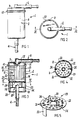
- Fig. 1 is a side view of a filter assembly according to one preferred embodiment of the present invention;
- Fig. 2 is top plan view of the filter assembly of Fig. 1;
- Fig. 3 is a sectional side view through section III-III of Fig. 1;
- Fig. 4 is a sectional plan view through section IV-IV of Fig. 3;
- Fig. 5 is a perspective view of the separator member of the filter assembly of Fig. 1;
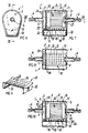
- Fig. 6 is an end view of a filter assembly according to another preferred embodiment of the present invention;
- Fig. 7 is a sectional side view through section VII-VII of Fig. 6;
- Fig. 8 is a sectional plan view through section VIII-VIII of Fig. 7;
- Fig. 9 is a perspective view of the separator member of the filter assembly of Fig. 6; and,
- Fig. 10 is a sectional side view of a filter assembly according to a further preferred embodiment of the present invention.
- Referring to the drawings there is generally shown alternative embodiments of filter assembly 1. Assembly 1 has housing 2 defining
filtering chamber 3. Housing 2 has aninlet tube 4 providing inlet port 5 communication withchamber 3, and alsooutlet tube 6 providing outlet port 7 communicating withchamber 3. As shown,inlet tube 4 and/oroutlet tube 6 may project a short distance intochamber 3 so that inlet port 5 and/or outlet port 7 are located withinchamber 3. -
Tubes chamber 3 and therefrom through port 7. - Inlet and outlet ports 5, 7 are co-axial and located toward opposite ends of housing 2. As shown, filter assembly 1 of Figs. 1 to 5 is intended for generally vertical, upward flow of liquid, whilst filter assemblies 1 of Figs. 6 to 9, and Fig. 10 are intended for generally horizontal flow of liquid.
- Housing 2 is of a generally enclosed cylindrical shape, although other shapes may be equally suitable. Housing 2 includes open
ended body 8 andclosure cap 9, which may be removable for access to filteringchamber 3, such as for maintenance.Cap 9 can be secured tobody 8 through any suitable connection arrangement, such as by means ofsnap connection 10, or a screw thread connection (not shown). - Housing 2 is of a generally integral construction. To that end,
inlet tube 4 can be molded or cast integral withbody 8, whilstoutlet tube 6 can be molded or cast integral withcap 9. It should be appreciated that, in particular,tubes body 8 andcap 9. - Housing 2 may be constructed of any suitable materials. Selection of materials may depend on the liquid to be filtered. In these embodiments, housing 2 is composed at least in part of transparent or translucent material to allow at least partial visual inspection of
filtering chamber 3. Conveniently, housing 2 is composed of plastics material. - Filter assembly 1 includes
filter media 11 inchamber 3 for filtering contaminants from liquid flowing therethough.Filter media 11 is particularly constructed for removing solid particulates from the liquid. -
Filter media 11 is in the form of filter cartridge 12 in these embodiments. Cartridge 12 is mounted inchamber 3 and includes generally annular filter member 13 andend caps inner chamber 16. Filter member 13 may be of any other suitable construction and, by way of example, may be composed of foam material. - End caps 14, 15 may be interferingly fitted over filter member 13 to assist in retaining the filter sheet material in the corrugated or pleated configuration. The filter sheet material may be paper or cardboard based material.
-
End cap 14 is closed, whilstend cap 15 hasaperture 17 therein into whichoutlet tube 6 projects for communication withinner chamber 16 of filter member 13. Filter member 13 is fixed in position inchamber 3 by connection ofend cap 15 tooutlet tube 6, although may be removable therefrom for cleaning and/or replacement. With this arrangement, liquid entering through inlet port 5 intochamber 3 can flow through filter member 13 intoinner chamber 16 and then to outlet port 7. In flowing through filter member 13, contaminants entrained in the liquid are trapped by filter member 13 in a typical filtering action. - Included within filtering chamber 13 is
sump region 18 into which contaminants in the liquid can be collected clear of filter member 13. Housing 2 is suitably shaped to accomodatesump region 18. To that end,sump region 18 may be located entirely in housing body 8 (as shown in the assembly of Figs. 1 to 5) or inbody 8 and cap 9 (as shown in the assemblies of Figs. 6 to 9 and Fig. 10). -
Sump region 18 is generally located at the bottom ofchamber 3, beneathfilter media 11 and also below inlet port 5. Thus, contaminants entrained inliquid entering chamber 3 can move under influence of gravity towardsump region 18. - Assembly 1 also includes
separator member 19 separatingfilter media 11 fromsump region 18.Separator member 19 facilitates separation of contaminants from the liquid and also acts to trap or retain contaminants received insump region 18. -
Separator member 19 includesseparator plate 20 extending acrosschamber 3, dividingfilter media 11 fromsump region 18.Plate 20 has an array ofopenings 21 therethrough for communication intosump region 18. In these embodiments,openings 21 are a regular grid array of circular holes between about 1 and 3 mm in diameter, although other opening arrays, shapes and sizes are envisaged, depending at least to some extent on the type of liquid and contaminants flowing through assembly 1. In an alternative embodiment (not shown)separator plate 20 may be composed of suitable graded mesh material. -
Separator member 19 is located inchamber 3 for limited movement during use of assembly 1. That movement is continuous vibration and is caused by vibration of housing 2 during use of assembly 1. In the exemplary application of assembly 1, vibration will be the result of associated engine operation and/or engine movement. Vibration ofseparator member 19 will be in directions of a general plane ofmember 19 and/or laterally of that plane. - The vibratory movement of
separator member 19, and particularlyplate 20, assists in separating contaminants from the liquid. In that regard,contaminants contacting plate 20 may be broken down by the vibratory effect. That is particularly so when the contaminants are conglomerates of particulate material. Moreover, the vibratory movement tends to cause any contaminants resting onplate 20 to gravitate toward and pass throughopenings 21. Once collected insump region 18, the continuous movement ofplate 20 reduces the likelihood of contaminants re-aligning withopenings 21 and passing back through them out ofsump region 18. That vibratory movement also inhibits purging ofsump region 18 of collected contaminants by flow of liquid aroundfilter media 11. That is particularly so in view of the small size ofopenings 21 and the rapid continuous vibration ofseparator member 19, even though some liquid will flow throughopenings 21 into and out ofsump region 18 on its way through filter assembly 1. - Trapping of contaminants in
sump region 18 removes those contaminants fromfilter media 11. That in turn may preserve the filtering integrity of filter member 13, thereby prolonging the operational life of assembly 1. In particular, removal of contaminants from filter member 13 prevents those contaminants from clogging, damaging or otherwise inhibiting the filtering effect of member 13. - In the embodiments shown in Figs. 1 to 5 and Figs. 6 to 9,
separator member 19 is shaped and sized so as to be loosely located inchamber 3. In this way,member 19 will tend to rattle during use of assembly 1 to cause the necessary vibratory movement. - In those assembly embodiments,
separator member 19 includes a plurality of support legs 22 (such as two as shown) projecting fromseparator plate 20.Plate 20 stands onsupport legs 22 which bear on housing 2 in order to correctly locateseparator plate 20. In an alternative arrangement (not shown) the support legs may be provided by housing 2 so thatplate 20 bears on them. - The location of
member 19 is such thatplate 20 will vibrate without rotating in its general plane. In the assembly embodiment of Figs. 1 to 5 that is achieved by providing housing 2 withlocation legs 23 which loosely engage incut outs 24 inplate 20, whilst in the assembly embodiment of Figs. 6 to 9 that is achieved by suitable shaping ofplate 20. Where assembly 1 can be dismantled for cleaning or other maintenance, thenseparator member 19 is removable from housing 2. - It should be appreciated that
separator member 19 may be otherwise located inchamber 3. By way of example, in one further assembly embodiment shown in Fig. 10,separator plate 20 has oneedge region 25 hingedly connected throughconnection 26 to housing 2 so as to generally locatemember 19 but permit vibratory movement thereof.Member 19 may include at least one support leg (not shown) extending fromplate 20 remote fromconnection 26 in order to supportplate 20. - Conveniently,
separator member 19 is of a one-piece construction.Member 19 may be composed of any suitable material, such as plastics material or metal. - Assembly 1 may optionally include
baffle member 27 infiltering chamber 3 to assist in removing contaminants from the liquid.Baffle member 27 is fixed between inlet port 5 andend cap 14 of filter cartridge 12, and extends at least substantially perpendicular to the flow of liquid entering through inlet port 5. In this way, liquid flowing intochamber 3 tends to impinge uponmember 27. This can have an effect on some contaminants that they are immediately redirected downwardly towardsump region 18, rather than onto filter member 13. To this extent,filter media 11 is protected against contact from those contaminants, which may in turn prolong filter assembly life. -
Baffle member 27 has an array ofopenings 28 for communication of liquid therethrough to filtermedia 11.Openings 28 may be of a similar configuration toopenings 21. - In operation of filter assembly 1, liquid with entrained contaminants flows through inlet port 5 and initially impacts upon end cap 14 (and/or baffle
member 27 if present). Thereafter, the liquid flows around and through filter cartridge 12 intoinner chamber 16 before passing through outlet port 7. During passage of the liquid throughchamber 3, entrained contaminants are progressively removed from the liquid by action offilter media 11,separator member 19 andbaffle member 27. Many of the contaminants will collect insump region 18, with the remaining contaminants collecting on filter member 13. - The filter assembly of the present invention has an extended effective or operational life when compared with prior similar assemblies.
- Finally, it should be appreciated that various modifications and/or alterations may be made to the filter assembly without departing from the ambit of the present invention as defined in the claims appended hereto.
Claims (16)
- A filter assembly (1) for filtering contaminants from liquid, including: a housing (2) providing a filtering chamber (3) and having an inlet port (5) and an outlet port (7) communicating with the chamber (3) for flow of liquid therethrough; filter media (11) in the filtering chamber (3) for filtering contaminants from liquid flowing through the chamber (3); a sump region (18) in the filtering chamber (3) at the bottom thereof below the inlet port (5) and positioned relative to the inlet port (5) so that contaminants, in the liquid flowing into the filtering chamber (3) from the inlet port (5), tend to gravitate toward the sump region (18) for collection; and a separator member (19) located in the filtering chamber (3) substantially separating the filter media (11) and sump region (18), the separator member (19) providing for communication into the sump region (18) of the contaminants which have gravitated to the separator member (19) and the separator member (19) tending to trap therein the contaminants received in the sump region (18); characterised in that:
the inlet port (5) and outlet port (7) are co-axially aligned and communicate with the chamber (3) through opposite ends of the housing (2); the filter media (11) is fixed in the housing (2) in co-axial alignment with the inlet and outlet ports (5,7) and in spaced, facing relation from the inlet port (5); the filter media (11) includes a filter cartridge (12) providing the filter member (13) and having an end cap (14) facing the inlet port (5) so that, in use, the liquid flows into the filtering chamber (3) through the inlet port (5) and is directed towards the filter cartridge (12) impinging upon the end cap (14) and deflecting about the filter cartridge (12) for subsequent flow through the filter member (13) to the outlet port (7); and, the separator member (19) is located in the filtering chamber (3) in spaced relation below the inlet port (5) substantially separating the filter cartridge (12) and sump region (18) thereby providing a gravitating space extending down from the inlet port (5) to the separator member (19) in which contaminants gravitate from the inlet port (5) to the separator member (19). - A filter assembly as claimed in claim 1, characterised in that the separator member (19) moves during use of the filter assembly (1) to facilitate separation of the contaminants from the liquid and collection in the sump region (18), the separator member (19) movement being caused by movement of the filter housing (2).
- A filter assembly as claimed in claim 1 or claim 2, characterised in that the separator member (19) is retained in the filtering chamber (3) for vibratory movement caused by housing movement during use of the filter assembly (1).
- A filter assembly as claimed in claim 2 or claim 3, characterised in that the separator member (19) is connected to the housing (2) for location within the filtering chamber (3), the connection (26) permitting the separator member (19) to move during use of the filter assembly (1).
- A filter assembly as claimed in claim 3, characterised in that the separator member (19) is loosely nested in the filtering chamber (3).
- A filtering assembly as claimed in claim 2, 3, 4 or 5, characterised in that the separator member (19) includes a separator plate (20) extending across the filtering chamber (3) between the filter media (11) and sump region (18).
- A filter assembly as claimed in claim 6, characterised in that the separator plate (20) is connected to the housing (2) for location of the plate (20) within the filtering chamber (3).
- A filter assembly as claimed in claim 7, characterised in that the separator plate (20) has an edge region (25) pivotably connected to the housing (2) so as to locate the plate (20) in the filtering chamber (3).
- A filter assembly as claimed in claim 6, characterised in that the separator member (19) has a plurality of legs (22) extending from the separator plate (20) and on which the separator member (19) stands in the filtering chamber (3).
- A filter assembly as claimed in claim 1, characterised in that the separator member (19) is positioned in the housing (2) so as to move relative to the housing (2) upon housing movement during use of the filter assembly (1).
- A filter assembly as claimed in claim 1, characterised in that the separator member (19) has an array of openings (21) therethrough providing communication for the contaminants into the sump region (18).
- A filter assembly as claimed in claim 1, characterised in that the housing (2) includes an inlet tube (4) providing the inlet port (5) and an outlet tube (6) providing the outlet port (7), the inlet and outlet tubes (4,6) extending horizontally during use of the filter assembly.
- A filter assembly as claimed in claim 1, characterised in that the housing (2) includes an inlet tube (4) providing the inlet port (5) and an outlet tube (6) providing the outlet port (7), the inlet and outlet tubes (4,6) extending vertically during use of the filter assembly (1).
- A filter assembly as claimed in claim 1, characterised in that a baffle member (27) is located in the filtering chamber (3) between the inlet port (5) and the filter media (11) so that liquid flowing into the filtering chamber (3) impinges upon the baffle member (27) causing at least some contaminants entrained in the liquid to deflect toward the sump region (18) for collection therein.
- A filter assembly as claimed in claim 14, characterised in that the baffle member (27) is located above the sump region (18) and extends across the filtering chamber (3) generally perpendicular to a longitudinal axis of the inlet port (5).
- A filter assembly as claimed in claim 15, characterized in that the baffle member (27) has an array of openings (28) therethrough providing liquid communication between the inlet port (5) and filter media (11).
Applications Claiming Priority (2)
| Application Number | Priority Date | Filing Date | Title |
|---|---|---|---|
| AUPJ378889 | 1989-04-20 | ||
| AU3788/89 | 1989-04-20 |
Publications (3)
| Publication Number | Publication Date |
|---|---|
| EP0393277A2 EP0393277A2 (en) | 1990-10-24 |
| EP0393277A3 EP0393277A3 (en) | 1991-07-10 |
| EP0393277B1 true EP0393277B1 (en) | 1994-06-22 |
Family
ID=3773867
Family Applications (1)
| Application Number | Title | Priority Date | Filing Date |
|---|---|---|---|
| EP89311669A Expired - Lifetime EP0393277B1 (en) | 1989-04-20 | 1989-11-10 | Filter assembly |
Country Status (10)
| Country | Link |
|---|---|
| US (1) | US5089132A (en) |
| EP (1) | EP0393277B1 (en) |
| JP (1) | JPH038403A (en) |
| KR (1) | KR900015789A (en) |
| AT (1) | ATE107530T1 (en) |
| AU (1) | AU631830B2 (en) |
| CA (1) | CA2011666C (en) |
| DE (1) | DE68916417D1 (en) |
| NZ (1) | NZ233341A (en) |
| ZA (1) | ZA902964B (en) |
Families Citing this family (12)
| Publication number | Priority date | Publication date | Assignee | Title |
|---|---|---|---|---|
| US5234589A (en) * | 1989-04-20 | 1993-08-10 | Kagisho Pty. Ltd. | Filter assembly |
| DE4134367A1 (en) * | 1991-10-17 | 1993-04-22 | Bosch Gmbh Robert | LIQUID FILTER |
| JPH0639107U (en) * | 1992-10-29 | 1994-05-24 | 株式会社ロキテクノ | Disposable capsule type filter with precipitation partition plate |
| US6293410B1 (en) * | 1999-06-29 | 2001-09-25 | Mahle-Parr Filter Systems, Inc. | No-cure fuel filter and method for making same |
| US6540909B2 (en) * | 2001-03-07 | 2003-04-01 | Davco Technology, Llc | Fluid filter with pressure relief valve |
| JP4552994B2 (en) * | 2007-10-12 | 2010-09-29 | 株式会社デンソー | Fuel supply device |
| RU2547746C2 (en) | 2009-09-17 | 2015-04-10 | Давко Текнолоджи, Ллс | Filter assembly with interface provided with dafety valve |
| JP2013136951A (en) * | 2011-12-28 | 2013-07-11 | Denso Corp | Fuel filter |
| JP2014125928A (en) * | 2012-12-26 | 2014-07-07 | Yamaha Motor Co Ltd | Fuel filter device |
| CN106075984A (en) * | 2016-08-08 | 2016-11-09 | 燕京啤酒(玉林)有限公司 | A kind of defecator of beer bottle washing machine heater |
| DE102017121647A1 (en) * | 2017-09-19 | 2019-03-21 | Illinois Tool Works Inc. | A filter assembly |
| EP4466082A4 (en) * | 2022-02-22 | 2026-01-07 | Oceaneering Int Inc | Hydraulic control line filter for underwater IDGH pressure application |
Family Cites Families (7)
| Publication number | Priority date | Publication date | Assignee | Title |
|---|---|---|---|---|
| US1035653A (en) * | 1912-03-06 | 1912-08-13 | John C Klatzl | Gasolene-filter. |
| US1723374A (en) * | 1928-04-02 | 1929-08-06 | Alexander H Roehr | Oil cleaner |
| GB324294A (en) * | 1929-04-13 | 1930-01-23 | Alexander Henry Roehr | Improvements in apparatus for filtering oil and other liquids |
| US2823804A (en) * | 1954-03-17 | 1958-02-18 | Myring Aksel | Filter combined with gravitation separator |
| JPS6027443Y2 (en) * | 1980-03-15 | 1985-08-19 | 本田技研工業株式会社 | fuel strainer |
| US4388187A (en) * | 1981-04-27 | 1983-06-14 | Eaglestone Dustin D | Fuel filter |
| SU1421890A1 (en) * | 1986-03-25 | 1988-09-07 | Научно-Производственное Объединение Космических Исследований При Ан Азсср | Fuel filter of vehicle internal combustion engine |
-
1989
- 1989-04-20 AU AU47318/89A patent/AU631830B2/en not_active Ceased
- 1989-09-21 US US07/410,601 patent/US5089132A/en not_active Expired - Fee Related
- 1989-11-10 DE DE68916417T patent/DE68916417D1/en not_active Expired - Lifetime
- 1989-11-10 AT AT89311669T patent/ATE107530T1/en not_active IP Right Cessation
- 1989-11-10 EP EP89311669A patent/EP0393277B1/en not_active Expired - Lifetime
-
1990
- 1990-03-07 CA CA002011666A patent/CA2011666C/en not_active Expired - Fee Related
- 1990-04-18 NZ NZ233341A patent/NZ233341A/en unknown
- 1990-04-19 ZA ZA902964A patent/ZA902964B/en unknown
- 1990-04-20 JP JP2105157A patent/JPH038403A/en active Pending
- 1990-04-20 KR KR1019900005549A patent/KR900015789A/en not_active Withdrawn
Also Published As
| Publication number | Publication date |
|---|---|
| EP0393277A2 (en) | 1990-10-24 |
| CA2011666A1 (en) | 1990-10-20 |
| ATE107530T1 (en) | 1994-07-15 |
| KR900015789A (en) | 1990-11-10 |
| NZ233341A (en) | 1992-12-23 |
| AU4731889A (en) | 1990-10-25 |
| US5089132A (en) | 1992-02-18 |
| EP0393277A3 (en) | 1991-07-10 |
| JPH038403A (en) | 1991-01-16 |
| AU631830B2 (en) | 1992-12-10 |
| DE68916417D1 (en) | 1994-07-28 |
| CA2011666C (en) | 1996-10-01 |
| ZA902964B (en) | 1991-02-27 |
Similar Documents
| Publication | Publication Date | Title |
|---|---|---|
| US3931011A (en) | Fluid separation apparatus | |
| US6599350B1 (en) | Filtration device for use with a fuel vapor recovery system | |
| US3546853A (en) | Covering and filtering apparatus for fuel tanks | |
| US5089132A (en) | Filter assembly | |
| US5505860A (en) | Grease and oil trap | |
| US5058693A (en) | Remote filter assembly for vapor recovery system | |
| CA1167774A (en) | Fuel filter assembly and cartridge | |
| RU2084647C1 (en) | Device for separating hazard emission discharging from crankcase of internal combustion engine | |
| US4485645A (en) | Foreign objects trap for automatic washer | |
| US7699042B2 (en) | Filtration device for use with a fuel vapor recovery system | |
| US4822387A (en) | Inverse flow depth filter assembly | |
| US5507944A (en) | Storm water drainage filter system | |
| US4476021A (en) | Rust, scale and foreign particle arrester | |
| US5637215A (en) | Fuel filter having improved communication with a contaminant container | |
| WO2016107751A2 (en) | 2-stage water separator pre-filter | |
| US3807144A (en) | Air rectifiers, apparatus with process | |
| US5234589A (en) | Filter assembly | |
| US20070294987A1 (en) | Natural gas filter for particulate and liquid impurities | |
| US4424128A (en) | Filter device for diesel engines | |
| US2988166A (en) | Air cleaner | |
| US3428180A (en) | Filter unit | |
| US1634463A (en) | Liquid trap and strainer | |
| US4388187A (en) | Fuel filter | |
| JPH04293612A (en) | Fresh-air suction path of automobile | |
| US3223244A (en) | Filter and dehydrator |
Legal Events
| Date | Code | Title | Description |
|---|---|---|---|
| PUAI | Public reference made under article 153(3) epc to a published international application that has entered the european phase |
Free format text: ORIGINAL CODE: 0009012 |
|
| AK | Designated contracting states |
Kind code of ref document: A2 Designated state(s): AT BE CH DE ES FR GB GR IT LI LU NL SE |
|
| PUAL | Search report despatched |
Free format text: ORIGINAL CODE: 0009013 |
|
| AK | Designated contracting states |
Kind code of ref document: A3 Designated state(s): AT BE CH DE ES FR GB GR IT LI LU NL SE |
|
| 17P | Request for examination filed |
Effective date: 19920109 |
|
| 17Q | First examination report despatched |
Effective date: 19920722 |
|
| GRAA | (expected) grant |
Free format text: ORIGINAL CODE: 0009210 |
|
| AK | Designated contracting states |
Kind code of ref document: B1 Designated state(s): AT BE CH DE ES FR GB GR IT LI LU NL SE |
|
| PG25 | Lapsed in a contracting state [announced via postgrant information from national office to epo] |
Ref country code: IT Free format text: LAPSE BECAUSE OF FAILURE TO SUBMIT A TRANSLATION OF THE DESCRIPTION OR TO PAY THE FEE WITHIN THE PRE;WARNING: LAPSES OF ITALIAN PATENTS WITH EFFECTIVE DATE BEFORE 2007 MAY HAVE OCCURRED AT ANY TIME BEFORE 2007. THE CORRECT EFFECTIVE DATE MAY BE DIFFERENT FROM THE ONE RECORDED.SCRIBED TIME-LIMIT Effective date: 19940622 Ref country code: GR Free format text: LAPSE BECAUSE OF FAILURE TO SUBMIT A TRANSLATION OF THE DESCRIPTION OR TO PAY THE FEE WITHIN THE PRESCRIBED TIME-LIMIT Effective date: 19940622 Ref country code: NL Effective date: 19940622 Ref country code: LI Effective date: 19940622 Ref country code: CH Effective date: 19940622 Ref country code: AT Effective date: 19940622 Ref country code: FR Effective date: 19940622 Ref country code: BE Effective date: 19940622 Ref country code: ES Free format text: THE PATENT HAS BEEN ANNULLED BY A DECISION OF A NATIONAL AUTHORITY Effective date: 19940622 |
|
| REF | Corresponds to: |
Ref document number: 107530 Country of ref document: AT Date of ref document: 19940715 Kind code of ref document: T |
|
| REF | Corresponds to: |
Ref document number: 68916417 Country of ref document: DE Date of ref document: 19940728 |
|
| PG25 | Lapsed in a contracting state [announced via postgrant information from national office to epo] |
Ref country code: SE Effective date: 19940922 |
|
| PG25 | Lapsed in a contracting state [announced via postgrant information from national office to epo] |
Ref country code: DE Effective date: 19940923 |
|
| REG | Reference to a national code |
Ref country code: CH Ref legal event code: PL |
|
| PG25 | Lapsed in a contracting state [announced via postgrant information from national office to epo] |
Ref country code: GB Effective date: 19941110 |
|
| EN | Fr: translation not filed | ||
| PG25 | Lapsed in a contracting state [announced via postgrant information from national office to epo] |
Ref country code: LU Free format text: LAPSE BECAUSE OF NON-PAYMENT OF DUE FEES Effective date: 19941130 |
|
| NLV1 | Nl: lapsed or annulled due to failure to fulfill the requirements of art. 29p and 29m of the patents act | ||
| PLBE | No opposition filed within time limit |
Free format text: ORIGINAL CODE: 0009261 |
|
| STAA | Information on the status of an ep patent application or granted ep patent |
Free format text: STATUS: NO OPPOSITION FILED WITHIN TIME LIMIT |
|
| 26N | No opposition filed | ||
| GBPC | Gb: european patent ceased through non-payment of renewal fee |
Effective date: 19941110 |