EP0393082B1 - Method for fixing a crossbar to a border prop, particularly in a cable rack, and a joint thus made as well as a bar profile for said joint - Google Patents
Method for fixing a crossbar to a border prop, particularly in a cable rack, and a joint thus made as well as a bar profile for said joint Download PDFInfo
- Publication number
- EP0393082B1 EP0393082B1 EP88909768A EP88909768A EP0393082B1 EP 0393082 B1 EP0393082 B1 EP 0393082B1 EP 88909768 A EP88909768 A EP 88909768A EP 88909768 A EP88909768 A EP 88909768A EP 0393082 B1 EP0393082 B1 EP 0393082B1
- Authority
- EP
- European Patent Office
- Prior art keywords
- crossbar
- web plate
- prop
- border
- end surface
- Prior art date
- Legal status (The legal status is an assumption and is not a legal conclusion. Google has not performed a legal analysis and makes no representation as to the accuracy of the status listed.)
- Expired - Lifetime
Links
- 238000000034 method Methods 0.000 title claims abstract description 19
- 239000007787 solid Substances 0.000 claims 1
- 210000002105 tongue Anatomy 0.000 description 5
- 230000006835 compression Effects 0.000 description 4
- 238000007906 compression Methods 0.000 description 4
- 238000003466 welding Methods 0.000 description 4
- 238000004080 punching Methods 0.000 description 3
- 229910052782 aluminium Inorganic materials 0.000 description 2
- XAGFODPZIPBFFR-UHFFFAOYSA-N aluminium Chemical compound [Al] XAGFODPZIPBFFR-UHFFFAOYSA-N 0.000 description 2
- 238000005520 cutting process Methods 0.000 description 2
- 238000005304 joining Methods 0.000 description 2
- 238000004519 manufacturing process Methods 0.000 description 2
- 238000003825 pressing Methods 0.000 description 2
- 239000004411 aluminium Substances 0.000 description 1
- 238000010276 construction Methods 0.000 description 1
- 238000009434 installation Methods 0.000 description 1
- 229910052751 metal Inorganic materials 0.000 description 1
- 239000002184 metal Substances 0.000 description 1
- 230000000149 penetrating effect Effects 0.000 description 1
- 230000002787 reinforcement Effects 0.000 description 1
Images

Classifications
-
- H—ELECTRICITY
- H02—GENERATION; CONVERSION OR DISTRIBUTION OF ELECTRIC POWER
- H02G—INSTALLATION OF ELECTRIC CABLES OR LINES, OR OF COMBINED OPTICAL AND ELECTRIC CABLES OR LINES
- H02G3/00—Installations of electric cables or lines or protective tubing therefor in or on buildings, equivalent structures or vehicles
- H02G3/02—Details
- H02G3/04—Protective tubing or conduits, e.g. cable ladders or cable troughs
- H02G3/0456—Ladders or other supports
-
- F—MECHANICAL ENGINEERING; LIGHTING; HEATING; WEAPONS; BLASTING
- F16—ENGINEERING ELEMENTS AND UNITS; GENERAL MEASURES FOR PRODUCING AND MAINTAINING EFFECTIVE FUNCTIONING OF MACHINES OR INSTALLATIONS; THERMAL INSULATION IN GENERAL
- F16B—DEVICES FOR FASTENING OR SECURING CONSTRUCTIONAL ELEMENTS OR MACHINE PARTS TOGETHER, e.g. NAILS, BOLTS, CIRCLIPS, CLAMPS, CLIPS OR WEDGES; JOINTS OR JOINTING
- F16B17/00—Connecting constructional elements or machine parts by a part of or on one member entering a hole in the other and involving plastic deformation
- F16B17/006—Connecting constructional elements or machine parts by a part of or on one member entering a hole in the other and involving plastic deformation of rods or tubes to sheets or plates
-
- F—MECHANICAL ENGINEERING; LIGHTING; HEATING; WEAPONS; BLASTING
- F16—ENGINEERING ELEMENTS AND UNITS; GENERAL MEASURES FOR PRODUCING AND MAINTAINING EFFECTIVE FUNCTIONING OF MACHINES OR INSTALLATIONS; THERMAL INSULATION IN GENERAL
- F16B—DEVICES FOR FASTENING OR SECURING CONSTRUCTIONAL ELEMENTS OR MACHINE PARTS TOGETHER, e.g. NAILS, BOLTS, CIRCLIPS, CLAMPS, CLIPS OR WEDGES; JOINTS OR JOINTING
- F16B5/00—Joining sheets or plates, e.g. panels, to one another or to strips or bars parallel to them
- F16B5/04—Joining sheets or plates, e.g. panels, to one another or to strips or bars parallel to them by means of riveting
- F16B5/045—Joining sheets or plates, e.g. panels, to one another or to strips or bars parallel to them by means of riveting without the use of separate rivets
Definitions
- This invention relates to a method for fixing a crossbar to a border prop, particularly in a cable rack, according to which method
- so called cable racks are used in factory halls, passageways and similar spaces, said cable racks being fixed to the ceiling or walls of said spaces and the cables being installed to rest on said cable racks.
- Cable racks are manufactured of separate parts formed by metallic profile bars, i.e. of two border props and a plurality of crossbars which are assembled into a supporting ladder of a U- or H-shaped cross-section.
- metallic profile bars i.e. of two border props
- crossbars To provide a rigid, firm structure, the crossbars must be secured with their ends to the border props either by welding or mechanically.
- mechanical fixing requires punching of some kind of fixing tongues at the ends of the crossbars and punching respective cuts in the border props and upsetting or twisting said tongues after the tongues have been pushed through the cuts.
- the mechanical fixing method is thus both laborious and slow and has generally been based on working the ends of the severed crossbar into fixing tongues.
- Finnish patent publication No. 68 305 suggests a method on account of which the crossbar can be mechanically secured to the border prop without need of working any fixing tongues at the end of the crossbar. Even though this method considerably simplifies the joining of the crossbar and prop, it still requires punching of cuts in the border prop and additionally a certain cross-sectional profile for the web plate of the border prop at the junction point.
- the object of this invention is to provide a method avoiding the above stated disadvantages and permitting the joining of the crossbar and prop simply and rapidly even at the installation site. This object is achieved by the method of the invention, which is characterized in
- the invention is based on the idea that the crossbar itself is caused to punch into the border prop the holes that are required for the crossbar simply by pressing the end of the crossbar against the border prop and similarly to form at the end of the crossbar the fixing elements that are required for the crossbar.
- the crossbar is pressed against the web plate of the border prop and the plate is supported from the opposite side with a suitable counterpart, those parts of the end of the crossbar at which there are recesses in the counterpart cut through the web plate, whereas those parts of the end of the crossbar against which there is a wall-supporting counterpart on the opposite side of the web plate of the border prop are collapsed against the web plate of the border prop without penetrating the plate.
- the fixing elements required by the joint are formed automatically by means of mere compressive force which can be easily generated by simple compression means.
- the locking of the peg-like fixing elements thus formed on the crossbar to the web plate of the border prop can also be effected in the same compression step wherein the fixing elements are formed. This can be realized so that the crossbar is pressed against the border prop so far that the ends of the fixing elements of the crossbar are upset against the counterpart.
- the invention also relates to a joint made according to this method, comprising fixing elements extending from the end surface of the crossbar through the web plate of the border prop and secured to the web plate on the opposite side thereof.
- a joint is characterized in that the fixing elements of the crossbar protrude through holes punched by the fixing elements themselves into the web plate and that the crossbar walls between the fixing elements are axially collapsed at least the thickness of the web plate.
- Such a joint can be simply produced, as has been stated in the above, and enables rigid attachment of the crossbar to the border prop.
- the joint does not require any special profile of the web plate of the border prop, but a smooth surface at the junction point is sufficient.
- the invention also relates to a bar profile for a hollow crossbar suitable for carrying out the method.
- a bar profile is characterized in that the wall of the bar profile has at least one axial continuous expansion forming a fixing element extending through the web plate of the border prop in the ready joint, and that the wall elements associated with the expansion are so thin that they can be axially collapsed to be located with their end surfaces in a plane different from that of the end surface of the expansion.
- Such a bar profile has the advantage that the crossbar can be cut from a bar profile into a piece of desired length whose end surfaces need not be worked in any way after right-angled cutting.
- the crossbar is ready as such to be disposed with its planar end surface against the planar surface of the border prop and to be secured to the prop.
- the cable rack 1 shown in the drawings is ladder-like and has a U-shaped cross-section, comprising two spaced-apart parallel border props 2 interconnected with a plurality of crossbars 3 spaced apart in the longitudinal direction of the props.
- the border props and crossbars have been cut into pieces of a suitable length from metal, preferably aluminum, profile bars.
- the border prop 2 forms a Planar web plate 4 and lengthwise reinforcement flanges 5 pertaining thereto.
- the crossbar 3 is constituted by a hollow piece of a substantially right-angled cross-section, and the crossbar has planar end surfaces 6 located perpendicularly to the longitudinal axis of the crossbar.
- Each corner of the crossbar has a lengthwise expansion 7 of a circular cross-section, and the expansions are connected relatively thin walls 8.
- the crossbar is disposed with its end surface 6 against the web plate 4 of the prop.
- a counterpart 9 is positioned against the web plate, the end surface 10 of said counterpart corresponding to at least the end surface of the crossbar exclusive of the regions corresponding to the expansions of the crossbar, at which regions the end surface of the counterpart has cylindrical recesses 11.
- the recess 11 has a diameter slightly greater than the diameter of the expansion 7 of the crossbar.
- the counterpart has been secured to a compression tool having gripping means which can be adjusted to grip the crossbar in an axially non-slidable manner and which can be forced toward the counterpart.
- the tool has been shown only schematically in Figure 2 by dotted lines.
- the ends of the fixing pegs are pressed, by means of the punch-severed piece of plate 14, against the bottoms of the recesses 11 in the counterpart, so that the ends of the pegs are upset and secure the fixing pegs to the web plate.
- the counterpart may be provided with suitable means reliably pushing the punch-severed piece of plate out from the recess after the removal of the counterpart.
- the web plate may have a smooth fixing surface, and that no protrusions or the like need be made at the end of the crossbar, but a straight-cut planar end surface is sufficient.
- the fixing method is very rapid, and the necessary compression means is of a simple construction.
Landscapes
- Engineering & Computer Science (AREA)
- General Engineering & Computer Science (AREA)
- Mechanical Engineering (AREA)
- Architecture (AREA)
- Civil Engineering (AREA)
- Structural Engineering (AREA)
- Details Of Indoor Wiring (AREA)
- Bridges Or Land Bridges (AREA)
- Mutual Connection Of Rods And Tubes (AREA)
- Variable-Direction Aerials And Aerial Arrays (AREA)
- Cable Transmission Systems, Equalization Of Radio And Reduction Of Echo (AREA)
- Monitoring And Testing Of Transmission In General (AREA)
- Connection Of Plates (AREA)
- Surgical Instruments (AREA)
- Clamps And Clips (AREA)
- Installation Of Indoor Wiring (AREA)
- Insertion, Bundling And Securing Of Wires For Electric Apparatuses (AREA)
- Hydrogenated Pyridines (AREA)
- Agricultural Chemicals And Associated Chemicals (AREA)
- Organic Low-Molecular-Weight Compounds And Preparation Thereof (AREA)
Abstract
Description
- This invention relates to a method for fixing a crossbar to a border prop, particularly in a cable rack, according to which method
- the crossbar is positioned with its end surface against a web plate of the border prop,
- the crossbar is secured to the border prop by means of fixing elements extending from the end surface of the crossbar through the web plate of the border prop, and
- a counterpart supporting the web plate in the region of the end surface of the crossbar is positioned at the fixing point of the crossbar, against the web plate of the border prop, and
- the web plate is supported by a counterpart in the region of the end surface of the crossbar. Such a method is for example known from GB-A-2068493
- To guide electric cables in groups from one location to another, so called cable racks are used in factory halls, passageways and similar spaces, said cable racks being fixed to the ceiling or walls of said spaces and the cables being installed to rest on said cable racks.
- Cable racks are manufactured of separate parts formed by metallic profile bars, i.e. of two border props and a plurality of crossbars which are assembled into a supporting ladder of a U- or H-shaped cross-section. To provide a rigid, firm structure, the crossbars must be secured with their ends to the border props either by welding or mechanically.
- Carrying out the fixing of the crossbars by welding, e.g. Finnish Patent No. 37 418, it is difficult to produce neat work, and welding will diminish the strength of the props and crossbars when said parts are manufactured of extruded aluminium profile bars. Welding requires of the crossbar a certain thickness and is more difficult to automatize than fixing carried out mechanically.
- On the other hand, mechanical fixing requires punching of some kind of fixing tongues at the ends of the crossbars and punching respective cuts in the border props and upsetting or twisting said tongues after the tongues have been pushed through the cuts. The mechanical fixing method is thus both laborious and slow and has generally been based on working the ends of the severed crossbar into fixing tongues.
- Finnish patent publication No. 68 305 suggests a method on account of which the crossbar can be mechanically secured to the border prop without need of working any fixing tongues at the end of the crossbar. Even though this method considerably simplifies the joining of the crossbar and prop, it still requires punching of cuts in the border prop and additionally a certain cross-sectional profile for the web plate of the border prop at the junction point.
- The object of this invention is to provide a method avoiding the above stated disadvantages and permitting the joining of the crossbar and prop simply and rapidly even at the installation site. This object is achieved by the method of the invention, which is characterized in
- that the web plate is supported in the region of the end surface of the crossbar, exclusive of the sites of the fixing elements of the crossbar, and
- that the end surface of the crossbar is pressed from the opposite side against the web plate of the border prop so that the wall of the crossbar is axially collapsed in the region supported by the counterpart, but cuts through the web plate of the border prop in the regions unsupported by the counterpart, forming said fixing elements extending through the web plate.
- The invention is based on the idea that the crossbar itself is caused to punch into the border prop the holes that are required for the crossbar simply by pressing the end of the crossbar against the border prop and similarly to form at the end of the crossbar the fixing elements that are required for the crossbar. When the crossbar is pressed against the web plate of the border prop and the plate is supported from the opposite side with a suitable counterpart, those parts of the end of the crossbar at which there are recesses in the counterpart cut through the web plate, whereas those parts of the end of the crossbar against which there is a wall-supporting counterpart on the opposite side of the web plate of the border prop are collapsed against the web plate of the border prop without penetrating the plate. Thus the fixing elements required by the joint are formed automatically by means of mere compressive force which can be easily generated by simple compression means.
- The locking of the peg-like fixing elements thus formed on the crossbar to the web plate of the border prop can also be effected in the same compression step wherein the fixing elements are formed. This can be realized so that the crossbar is pressed against the border prop so far that the ends of the fixing elements of the crossbar are upset against the counterpart.
- The invention also relates to a joint made according to this method, comprising fixing elements extending from the end surface of the crossbar through the web plate of the border prop and secured to the web plate on the opposite side thereof. Such a joint is characterized in that the fixing elements of the crossbar protrude through holes punched by the fixing elements themselves into the web plate and that the crossbar walls between the fixing elements are axially collapsed at least the thickness of the web plate.
- Such a joint can be simply produced, as has been stated in the above, and enables rigid attachment of the crossbar to the border prop. The joint does not require any special profile of the web plate of the border prop, but a smooth surface at the junction point is sufficient.
- The invention also relates to a bar profile for a hollow crossbar suitable for carrying out the method. Such a bar profile is characterized in that the wall of the bar profile has at least one axial continuous expansion forming a fixing element extending through the web plate of the border prop in the ready joint, and that the wall elements associated with the expansion are so thin that they can be axially collapsed to be located with their end surfaces in a plane different from that of the end surface of the expansion.
- Such a bar profile has the advantage that the crossbar can be cut from a bar profile into a piece of desired length whose end surfaces need not be worked in any way after right-angled cutting. Thus, subsequent to cutting the crossbar is ready as such to be disposed with its planar end surface against the planar surface of the border prop and to be secured to the prop.
- The following is a more detailed description of the invention with reference to the accompanying drawings, wherein
- Figure 1 is a perspective view of a cable rack wherein the fixing method of the invention has been implemented,
- Figure 2 shows in a larger size a crossbar and a border prop as well as a counterpart for a cable rack, detached from one another prior to the fixing of the crossbar,
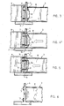
- Figures 3, 4 and 5 are side projections of the steps of producing a joint between the crossbar and prop at the beginning, intermediate step, and end of the fixing respectively,
- Figure 6 shows a ready joint seen in the direction of the prop, and
- Figures 7 and 8 are perspective views of a crossbar cut from a profile bar prior to the manufacturing of the joint and thereafter, respectively.
- The
cable rack 1 shown in the drawings is ladder-like and has a U-shaped cross-section, comprising two spaced-apartparallel border props 2 interconnected with a plurality ofcrossbars 3 spaced apart in the longitudinal direction of the props. The border props and crossbars have been cut into pieces of a suitable length from metal, preferably aluminum, profile bars. - The
border prop 2 forms a Planarweb plate 4 and lengthwisereinforcement flanges 5 pertaining thereto. - The
crossbar 3 is constituted by a hollow piece of a substantially right-angled cross-section, and the crossbar hasplanar end surfaces 6 located perpendicularly to the longitudinal axis of the crossbar. Each corner of the crossbar has alengthwise expansion 7 of a circular cross-section, and the expansions are connected relativelythin walls 8. - To fix the border prop and crossbar to one another, the crossbar is disposed with its
end surface 6 against theweb plate 4 of the prop. On the opposite side of the fixing point, acounterpart 9 is positioned against the web plate, theend surface 10 of said counterpart corresponding to at least the end surface of the crossbar exclusive of the regions corresponding to the expansions of the crossbar, at which regions the end surface of the counterpart hascylindrical recesses 11. Therecess 11 has a diameter slightly greater than the diameter of theexpansion 7 of the crossbar. - The counterpart has been secured to a compression tool having gripping means which can be adjusted to grip the crossbar in an axially non-slidable manner and which can be forced toward the counterpart. The tool has been shown only schematically in Figure 2 by dotted lines.
- When the crossbar is pressed by means of the tool against the web plate of the border prop simultaneously as the counterpart is tightly pressed from the opposite side against the web plate, the
expansions 7 of the crossbar cut through the web plate, whereas thewall sections 8 of the crossbar are axially collapsed, 8a, the counterpart serving as an anvil on the opposite side of the web plate. The expansions of the crossbar thus punch roundholes 12 into the web plate and formcylindrical fixing pegs 13 extending through the web plate. When the pressing of the crossbar against the web plate is still slightly continued, the ends of the fixing pegs are pressed, by means of the punch-severed piece ofplate 14, against the bottoms of therecesses 11 in the counterpart, so that the ends of the pegs are upset and secure the fixing pegs to the web plate. The counterpart may be provided with suitable means reliably pushing the punch-severed piece of plate out from the recess after the removal of the counterpart. - It is noted that no cuts or the like need be made in the border prop in advance, but the web plate may have a smooth fixing surface, and that no protrusions or the like need be made at the end of the crossbar, but a straight-cut planar end surface is sufficient. The fixing method is very rapid, and the necessary compression means is of a simple construction.
- The drawing and the description pertaining thereto are intended merely to illustrate the idea of the invention. Even though the invention has been explained in the foregoing mainly in connection with a cable rack, it is evident that the fixing method according to the invention is suitable for application to the production of other objects as well, said objects involving securing a bar to a plate-like element. The expansions forming the fixing elements may vary in their form and location considerably, depending on the joint involved in each case. The invention can thus vary within the scope of the claims.
Claims (7)
- A method for fixing a crossbar (3) to a border prop (2), particularly in a cable rack (1), according to which method- the crossbar (3) is positioned with its end surface (6) against a web plate (4) of the border prop (2),- the crossbar is secured to the border prop by means of fixing elements (13) extending from the end surface of the crossbar through the web plate of the border prop,- a counterpart (9) supporting the web plate in the region of the end surface (6) of the crossbar is positioned at the fixing point of the crossbar (3), against the web plate (4) of the border prop (2), and- the web plate (4) is supported by a counterpart (9) in the region of the end surface of the crossbar, characterized in- that the web plate (4) is supported by the counterpart (9) in the end surface region exclusive of the sites of the fixing elements (13) of the crossbar, and- that the planar end surface (6) of the crossbar is pressed from the opposite side against the web plate (4) of the border prop so that a wall (8) of the crossbar is axially collapsed (8a) in the region supported by the counterpart, but cuts through the web plate of the border prop in the regions unsupported by the counterpart, forming said fixing elements (13) extending through the web plate.
- A method as claimed in claim 1, characterized in that the crossbar (3) is pressed against the border prop (2) so far that the ends of the fixing elements (13) of the crossbar are upset against the counterpart (9).
- A method as claimed in claim 1 or 2, characterized in that the crossbar (3) is cut perpendicularly to the longitudinal axis thereof and that the planar end surface (6) of the crossbar is pressed against the planar surface of the web plate (4) of the border prop (2).
- A joint between a crossbar and a border prop, comprising fixing elements (13) extending from an end surface (6) of the crossbar (3) through a web plate (4) of the border prop (2) and fixed to said web plate on the opposite side thereof, characterized in that the fixing elements (13) of the crossbar (3) extend through holes (12) punched by the fixing elements themselves into the web plate and that the walls (8) of the crossbar between the fixing elements are axially collapsed (8a) at least the thickness of the web plate.
- A joint as claimed in claim 4, characterized in that the walls (8) of the crossbar (3) are collapsed (8a) more than the thickness of the web plate (4) of the border prop (2) and that the protruding ends of the fixing elements (13) have been upset against the web plate.
- A bar profile for a hollow crossbar (3) to be fixed to a border prop (2), characterized in that a wall of the bar profile has at least one axial continuous expansion (7) forming in a ready joint a fixing element (13) extending through a web plate (4) of the border prop, and that the wall sections (8) associated with the expansion are so thin that they can be axially collapsed (8a) to be located with their end surfaces in a plane different from that of the end surface of the expansion (7).
- A bar profile as claimed in claim 6, characterized in that the expansion (7) is solid.
Priority Applications (1)
| Application Number | Priority Date | Filing Date | Title |
|---|---|---|---|
| AT88909768T ATE80926T1 (en) | 1987-11-03 | 1988-10-31 | METHOD OF ATTACHING A CROSSBAR ON A SIDE POST, PARTICULARLY IN A CABLE RACK AND JOINT SO SHAPED AND A PROFILE ROD FOR THAT CONNECTION. |
Applications Claiming Priority (2)
| Application Number | Priority Date | Filing Date | Title |
|---|---|---|---|
| FI874841A FI79175C (en) | 1987-11-03 | 1987-11-03 | Method of attaching a cross bar to an edge stretcher, especially in a cable shelf and a dressing thus formed |
| FI874841 | 1987-11-03 |
Publications (2)
| Publication Number | Publication Date |
|---|---|
| EP0393082A1 EP0393082A1 (en) | 1990-10-24 |
| EP0393082B1 true EP0393082B1 (en) | 1992-09-23 |
Family
ID=8525343
Family Applications (1)
| Application Number | Title | Priority Date | Filing Date |
|---|---|---|---|
| EP88909768A Expired - Lifetime EP0393082B1 (en) | 1987-11-03 | 1988-10-31 | Method for fixing a crossbar to a border prop, particularly in a cable rack, and a joint thus made as well as a bar profile for said joint |
Country Status (8)
| Country | Link |
|---|---|
| EP (1) | EP0393082B1 (en) |
| AT (1) | ATE80926T1 (en) |
| DE (1) | DE3874895T2 (en) |
| DK (1) | DK169485B1 (en) |
| FI (1) | FI79175C (en) |
| NO (1) | NO173464C (en) |
| SE (1) | SE464721B (en) |
| WO (1) | WO1989004430A1 (en) |
Families Citing this family (1)
| Publication number | Priority date | Publication date | Assignee | Title |
|---|---|---|---|---|
| DE202014101758U1 (en) * | 2014-04-14 | 2015-07-17 | Obo Bettermann Gmbh & Co. Kg | cable conductor |
Family Cites Families (4)
| Publication number | Priority date | Publication date | Assignee | Title |
|---|---|---|---|---|
| FR1332164A (en) * | 1961-08-11 | 1963-12-16 | ||
| SE327313B (en) * | 1969-05-09 | 1970-08-17 | Hakanssons Ind Ab | |
| CA1009428A (en) * | 1973-07-09 | 1977-05-03 | Robert J. Reid | Method of forming structural joints |
| DE3003908C2 (en) * | 1980-02-02 | 1984-10-18 | Profil-Verbindungstechnik Gmbh & Co Kg, 6382 Friedrichsdorf | Stud bolts with punching and riveting behavior |
-
1987
- 1987-11-03 FI FI874841A patent/FI79175C/en not_active IP Right Cessation
-
1988
- 1988-10-31 EP EP88909768A patent/EP0393082B1/en not_active Expired - Lifetime
- 1988-10-31 AT AT88909768T patent/ATE80926T1/en not_active IP Right Cessation
- 1988-10-31 WO PCT/FI1988/000177 patent/WO1989004430A1/en not_active Ceased
- 1988-10-31 DE DE8888909768T patent/DE3874895T2/en not_active Expired - Fee Related
-
1990
- 1990-04-30 SE SE9001552A patent/SE464721B/en not_active IP Right Cessation
- 1990-05-02 NO NO901955A patent/NO173464C/en unknown
- 1990-05-02 DK DK109090A patent/DK169485B1/en active
Also Published As
| Publication number | Publication date |
|---|---|
| FI79175B (en) | 1989-07-31 |
| NO901955D0 (en) | 1990-05-02 |
| NO901955L (en) | 1990-06-21 |
| SE9001552D0 (en) | 1990-04-30 |
| FI79175C (en) | 1989-11-10 |
| SE464721B (en) | 1991-06-03 |
| DE3874895D1 (en) | 1992-10-29 |
| FI874841L (en) | 1989-05-04 |
| NO173464B (en) | 1993-09-06 |
| NO173464C (en) | 1993-12-15 |
| EP0393082A1 (en) | 1990-10-24 |
| DK169485B1 (en) | 1994-11-07 |
| FI874841A0 (en) | 1987-11-03 |
| WO1989004430A1 (en) | 1989-05-18 |
| ATE80926T1 (en) | 1992-10-15 |
| DK109090A (en) | 1990-05-02 |
| DE3874895T2 (en) | 1993-03-04 |
| DK109090D0 (en) | 1990-05-02 |
| SE9001552L (en) | 1990-04-30 |
Similar Documents
| Publication | Publication Date | Title |
|---|---|---|
| KR102479473B1 (en) | Cable tray | |
| US3083794A (en) | Joined sheet metal structures | |
| US3284971A (en) | Structural elements for metal framing systems | |
| US5839848A (en) | Joining metal members | |
| AU5886199A (en) | Building frame and method of construction | |
| KR100256390B1 (en) | Wall board and the profiles of it | |
| US6088902A (en) | Method of fixing a tubular metal member in an aperture and tool therefor | |
| WO1989004430A1 (en) | Method for fixing a crossbar to a border prop, particularly in a cable rack, and a joint thus made as well as a bar profile for said joint | |
| EP0248017B1 (en) | Beam and method for the producing thereof | |
| EP0380529B1 (en) | Tray for cables and method of the manufacturing thereof | |
| EP0360309B1 (en) | Mounting system for partition walls | |
| EP1687106B1 (en) | Structural beam with openings and it's method of manufacturing | |
| EP4077824B1 (en) | Clip connector for connecting two studs | |
| JP2821107B2 (en) | Shaped steel member with drawn portion for building, joint structure and method of manufacturing the same | |
| JP4503092B1 (en) | Hollow extruded profile | |
| WO2023044137A1 (en) | Steel thermal stud | |
| KR20090078495A (en) | Tube fixing rack | |
| JP4380516B2 (en) | Aluminum truss structure | |
| WO1995020081A1 (en) | Body structure | |
| US3059293A (en) | Truss connection | |
| WO1991015314A1 (en) | Joining structural elements | |
| FI68305B (en) | CABLE SHELF FOR MONTERING AV ELECTRIC CABLE | |
| CA2548028C (en) | Roof truss | |
| KR20240051557A (en) | Rung of cable tray | |
| JP6442303B2 (en) | fence |
Legal Events
| Date | Code | Title | Description |
|---|---|---|---|
| PUAI | Public reference made under article 153(3) epc to a published international application that has entered the european phase |
Free format text: ORIGINAL CODE: 0009012 |
|
| 17P | Request for examination filed |
Effective date: 19900426 |
|
| AK | Designated contracting states |
Kind code of ref document: A1 Designated state(s): AT BE CH DE FR GB IT LI LU NL SE |
|
| 17Q | First examination report despatched |
Effective date: 19911113 |
|
| RAP1 | Party data changed (applicant data changed or rights of an application transferred) |
Owner name: NOKIA ALUMIINI OY |
|
| GRAA | (expected) grant |
Free format text: ORIGINAL CODE: 0009210 |
|
| AK | Designated contracting states |
Kind code of ref document: B1 Designated state(s): AT BE CH DE FR GB IT LI LU NL SE |
|
| PG25 | Lapsed in a contracting state [announced via postgrant information from national office to epo] |
Ref country code: BE Effective date: 19920923 Ref country code: IT Free format text: LAPSE BECAUSE OF FAILURE TO SUBMIT A TRANSLATION OF THE DESCRIPTION OR TO PAY THE FEE WITHIN THE PRE;WARNING: LAPSES OF ITALIAN PATENTS WITH EFFECTIVE DATE BEFORE 2007 MAY HAVE OCCURRED AT ANY TIME BEFORE 2007. THE CORRECT EFFECTIVE DATE MAY BE DIFFERENT FROM THE ONE RECORDED.SCRIBED TIME-LIMIT Effective date: 19920923 Ref country code: CH Effective date: 19920923 Ref country code: FR Effective date: 19920923 Ref country code: NL Effective date: 19920923 Ref country code: LI Effective date: 19920923 Ref country code: SE Effective date: 19920923 |
|
| REF | Corresponds to: |
Ref document number: 80926 Country of ref document: AT Date of ref document: 19921015 Kind code of ref document: T |
|
| REF | Corresponds to: |
Ref document number: 3874895 Country of ref document: DE Date of ref document: 19921029 |
|
| PG25 | Lapsed in a contracting state [announced via postgrant information from national office to epo] |
Ref country code: LU Free format text: LAPSE BECAUSE OF NON-PAYMENT OF DUE FEES Effective date: 19921031 |
|
| REG | Reference to a national code |
Ref country code: CH Ref legal event code: PL |
|
| EN | Fr: translation not filed | ||
| NLV1 | Nl: lapsed or annulled due to failure to fulfill the requirements of art. 29p and 29m of the patents act | ||
| PLBE | No opposition filed within time limit |
Free format text: ORIGINAL CODE: 0009261 |
|
| STAA | Information on the status of an ep patent application or granted ep patent |
Free format text: STATUS: NO OPPOSITION FILED WITHIN TIME LIMIT |
|
| 26N | No opposition filed | ||
| PGFP | Annual fee paid to national office [announced via postgrant information from national office to epo] |
Ref country code: GB Payment date: 19971006 Year of fee payment: 10 |
|
| PGFP | Annual fee paid to national office [announced via postgrant information from national office to epo] |
Ref country code: DE Payment date: 19971015 Year of fee payment: 10 |
|
| PGFP | Annual fee paid to national office [announced via postgrant information from national office to epo] |
Ref country code: AT Payment date: 19971028 Year of fee payment: 10 |
|
| PG25 | Lapsed in a contracting state [announced via postgrant information from national office to epo] |
Ref country code: AT Free format text: LAPSE BECAUSE OF NON-PAYMENT OF DUE FEES Effective date: 19981031 Ref country code: GB Free format text: LAPSE BECAUSE OF NON-PAYMENT OF DUE FEES Effective date: 19981031 |
|
| GBPC | Gb: european patent ceased through non-payment of renewal fee |
Effective date: 19981031 |
|
| PG25 | Lapsed in a contracting state [announced via postgrant information from national office to epo] |
Ref country code: DE Free format text: LAPSE BECAUSE OF NON-PAYMENT OF DUE FEES Effective date: 19990803 |