EP0392964B1 - Verschlussring für ein Erdölsondenwerkzeug - Google Patents
Verschlussring für ein Erdölsondenwerkzeug Download PDFInfo
- Publication number
- EP0392964B1 EP0392964B1 EP90630082A EP90630082A EP0392964B1 EP 0392964 B1 EP0392964 B1 EP 0392964B1 EP 90630082 A EP90630082 A EP 90630082A EP 90630082 A EP90630082 A EP 90630082A EP 0392964 B1 EP0392964 B1 EP 0392964B1
- Authority
- EP
- European Patent Office
- Prior art keywords
- collet ring
- shoulder
- housing
- tubular member
- threaded section
- Prior art date
- Legal status (The legal status is an assumption and is not a legal conclusion. Google has not performed a legal analysis and makes no representation as to the accuracy of the status listed.)
- Expired - Lifetime
Links
- 239000003129 oil well Substances 0.000 title 1
- 238000005553 drilling Methods 0.000 description 5
- 230000004323 axial length Effects 0.000 description 2
- 230000013011 mating Effects 0.000 description 2
- 239000004568 cement Substances 0.000 description 1
- 238000010276 construction Methods 0.000 description 1
- 230000001419 dependent effect Effects 0.000 description 1
- 230000007246 mechanism Effects 0.000 description 1
- 230000000717 retained effect Effects 0.000 description 1
Images

Classifications
-
- F—MECHANICAL ENGINEERING; LIGHTING; HEATING; WEAPONS; BLASTING
- F16—ENGINEERING ELEMENTS AND UNITS; GENERAL MEASURES FOR PRODUCING AND MAINTAINING EFFECTIVE FUNCTIONING OF MACHINES OR INSTALLATIONS; THERMAL INSULATION IN GENERAL
- F16L—PIPES; JOINTS OR FITTINGS FOR PIPES; SUPPORTS FOR PIPES, CABLES OR PROTECTIVE TUBING; MEANS FOR THERMAL INSULATION IN GENERAL
- F16L15/00—Screw-threaded joints; Forms of screw-threads for such joints
- F16L15/08—Screw-threaded joints; Forms of screw-threads for such joints with supplementary elements
-
- E—FIXED CONSTRUCTIONS
- E21—EARTH OR ROCK DRILLING; MINING
- E21B—EARTH OR ROCK DRILLING; OBTAINING OIL, GAS, WATER, SOLUBLE OR MELTABLE MATERIALS OR A SLURRY OF MINERALS FROM WELLS
- E21B17/00—Drilling rods or pipes; Flexible drill strings; Kellies; Drill collars; Sucker rods; Cables; Casings; Tubings
- E21B17/02—Couplings; joints
- E21B17/04—Couplings; joints between rod or the like and bit or between rod and rod or the like
- E21B17/06—Releasing-joints, e.g. safety joints
-
- E—FIXED CONSTRUCTIONS
- E21—EARTH OR ROCK DRILLING; MINING
- E21B—EARTH OR ROCK DRILLING; OBTAINING OIL, GAS, WATER, SOLUBLE OR MELTABLE MATERIALS OR A SLURRY OF MINERALS FROM WELLS
- E21B33/00—Sealing or packing boreholes or wells
- E21B33/02—Surface sealing or packing
- E21B33/03—Well heads; Setting-up thereof
- E21B33/04—Casing heads; Suspending casings or tubings in well heads
- E21B33/043—Casing heads; Suspending casings or tubings in well heads specially adapted for underwater well heads
Definitions
- This invention relates in general to devices for connecting a tubular member into a tubular housing, and in particular to a locking ring that connects a string of conduit to a casing hanger being lowered into a subsea wellhead housing.
- a running tool will be latched into a casing hanger at the drilling vessel.
- the casing hanger will be located at the top of a string of casing being lowered into the well.
- the running tool lowers the casing hanger into position within a subsea wellhead housing located on the sea floor. Once in place, the running tool may be released and pulled to the surface.
- US-A-4 714 111 discloses a connection means for securing a tubular member into a tubular housing having a bore , a frusto-conical threaded section on the tubular member having a set of threads ; at least one circumferential recess formed in the bore of the housing , defining an upward facing lower shoulder and a downward facing upper shoulder; a collet ring having a set of internal threads , an external downward facing lower shoulder (lower portion of a split ring), slot means formed in the collet ring to allow at least the upper portion of the collet ring to expand radially outward from a relaxed position to an engaged position, the internal threads of the collet ring having a generally cylindrical configuration while in the relaxed position; anti-rotation means in the housing for preventing rotation of the collet ring relative to the housing, enabling the tubular member to be removed from the housing by rotating the tubular member from the housing by rotating the tubular member to unscrew the internal threads from the
- the circumferential recess receives split ring positioned on the tubular member for supporting said tubular member relative to the tubular housing prior to and during setting of a pack-off.
- the pack-off when set expands the split ring outward into the circumferential recess which now supports via the split ring, the pack-off, a pack-off drive nut and the collet ring received in the drive nut, the tubular member engaged with its threaded section into the threads in the collet ring.
- connection means for securing a tubular member into a tubular housing having a bore comprising in combination: a frusto-conical threaded section on the tubular member having a set of threads; at least one circumferential recess formed in the bore of the housing, defining an upward facing lower shoulder and a downward facing upper shoulder; a collet ring having a set of internal threads, an external downward facing lower shoulder and an external upward facing upper shoulder; slot means formed in the collet ring to allow at least the upper portion of the collet ring to expand radially outward from a relaxed position to an engaged position; and anti-rotation means in the housing for preventing rotation of the collet ring relative to the housing, enabling the tubular member to be removed from the housing by rotating the tubular member to unscrew the internal threads from the threaded section; the internal threads of the collet ring having a generally cylindrical configuration while in the relaxed position, and having a frusto-con
- the running tool or tubular member has a frusto-conical threaded section.
- a nose section extends below the threaded section a selected distance.
- the housing or casing hanger into which the tubular member stabs has a circumferential recess.
- a collet ring is carried on the running tool, initially on the nose section below the threaded section.
- the collet ring has internal threads and an external load shoulder.
- the collet ring has slots that allow it to expand from a cylindrical shape to a frusto-conical shape once the collet lands on the casing hanger recess.
- An anti-rotation pin in the casing hanger prevents rotation of the collet ring. This enables the running tool to be removed from the casing hanger by rotation.
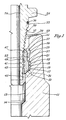
- casing hanger 11 comprises a housing having a bore 13 extending through it.
- a string of casing (not shown) will be connected to the lower end of casing hanger 11.
- Bore 13 has a shoulder 14.
- a lower recess 15 is located above the shoulder 14.
- Lower recess 15 has a lower shoulder 17 which is frusto-conical and faces upward.
- Lower recess 15 has a side or base 19 which is a frusto-conical surface, also.
- Base 19 converges from a larger diameter at its upper termination to a lesser diameter at its intersection with the lower shoulder 17.
- the upper end of base 19 joins an intermediate shoulder 21.
- Intermediate shoulder 21 is frusto-conical and faces downward.
- An upper recess 23 extends upward from the intermediate shoulder 21.
- Upper recess 23 has a base 25 that is frusto-conical.
- Base 25 is at the same inclination as the lower recess base 19. It has a larger diameter at its upper termination than at its lower termination.
- An upper shoulder 27 is located at the upper end of the base 25.
- the upper shoulder 27 is frusto-conical and faces generally downward, parallel with the intermediate shoulder 21.
- a rim 29 is formed on the upper end of the casing hanger 11. Rim 29 is slightly conical.
- An anti-rotation pin 31 protrudes upward from the lower shoulder 17.
- a running tool 33 will locate in the bore 13 of casing hanger 11.
- Running tool 33 is a tubular member having a bore 32 that is coaxial with the bore 13.
- the upper end of running tool 33 will normally be secured to casing (not shown) which is used to lower the running tool 33 and casing hanger 11 into the wellhead housing (not shown) on the subsea floor.
- An external flange 34 extends radially outward from the running tool 33.
- Flange 34 has a lower side that is adapted to contact the casing hanger rim 29 when the running tool 33 is stabbed into the casing hanger 11.
- Running tool 33 has a threaded section 35 that begins a selected distance below the flange 34. The portion of the running tool 33 between the threaded section 35 and the flange 34 is cylindrical and contains an O-ring seal 36.
- the threaded section 35 is frusto-conical. It tapers from a larger diameter at its upper termination to a smaller diameter at the lower termination.
- the threads of threaded section 35 are preferably left-hand. Also, they preferably are of a multi-start type, containing a plurality of separate threads, such as three, each of which extends the full length of the threaded section 35.
- the threads of threaded section 35 are generally of a saw-tooth configuration. Each has an upper flank 37 that is at a sight inclination relative to the axis of bore 32. That is, each upper flank 37 is at a few degrees relative to a plane that is perpendicular to the axis of the bore 32. The slope is slightly downward proceeding from the outer edge of each flank 37 inward. Each thread of threaded section 35 also has a lower flank 39. Lower flank 39 inclines downward at a considerably greater angle than the upper flank 37.
- Running tool 33 has a nose section 41 that extends downward from the lower end of the threaded section 35.
- Nose section 41 is cylindrical and of a smaller diameter than the running tool 33 at the seal 36.
- the axial length of nose section 41 is somewhat greater than the axial length of the threaded section 35.
- Two threads or teeth 43 are located on the nose section 41 between its ends.
- the threads 43 have the same configuration as the threads of the threaded section 35 and are left-hand.
- a threaded retaining ring 45 secures to the lower end of the nose section 41.
- Retaining ring 45 retains a collet ring 47 on the nose section 41.
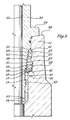
- the collet ring 47 will move from an initial relaxed position shown in Figure 1 to an engaged latching position shown in Figure 2.
- the threads 43 retain the collet ring 47 in the initial position while the running tool 33 is being lowered into the casing hanger 11.
- Collet ring 47 has a threaded section 49. While in the initial position, threaded section 49 is cylindrical. The threads of the threaded section 49 are of the same configuration as the threads of the running tool threaded section 35. They are multi-start and left-hand. While in the initial position, the threads 43 engage two of the threads of the threaded section 49.
- Collet ring 47 has a lower shoulder 51. Shoulder 51 will contact the casing hanger lower shoulder 17 when the running tool 33 is stabbed into the casing hanger 11. Lower shoulder 51 is frusto-conical to mate with the casing hanger shoulder 17. A plurality of cavities or recesses 53 (Fig. 3) are located in the lower shoulder 51. The anti-rotation pin 31 will locate within one of the recesses 53 to prevent rotation of the collet ring 47.
- Collet ring 47 has an intermediate shoulder 57 that faces upward and outward. Intermediate shoulder 57 is positioned to engage the intermediate shoulder 21. Collet ring 47 has a lower exterior wall 55 that extends upward from the lower shoulder 51 to intermediate shoulder 57. An upper exterior wall 59 extends upward from the intermediate shoulder 57. While in the initial position, the exterior walls 55, 59 are cylindrical. While in the latching position, they deflect outward to take on a frusto-conical configuration with the same taper as the recess bases 19 and 25. Collet ring 47 has an upper shoulder 61 located at its upper end. Upper shoulder 61 is frusto-conical for mating with the recess upper shoulder 27.
- Collet ring 47 has slot means which allows the upper portion of the collet ring 47 to deflect outward when moving to its latched position.
- the slot means includes a plurality of upper slots 65.
- the upper slots 65 extend through the wall of the collet ring 47 beginning at the upper shoulder 61.
- the upper slots 65 extend downward to a point above the collet ring lower shoulder 51. In the preferred embodiment there are about 24 upper slots 65 spaced around the collet ring 47.
- the lower slot 67 extend from the lower shoulder 51 upward to a point below the upper shoulder 61.
- a string of casing will be made up and lowered into the well from the drilling vessel.
- the casing hanger 11 will be secured to the upper end of the string of casing.
- the running tool 33 will be secured to the casing hanger 11 while both are located on the drilling vessel.
- the collet ring 47 will be screwed onto the nose section 41.
- the threads 43 will engage the threaded section 49 of the collet ring 47.
- the retaining ring 45 will be secured in place. All of the threads of the threaded section 49 will be located below the threaded section 35.
- the collet ring threaded section 47 will be cylindrical in configuration in this initial position.
- the running tool 33 will be stabbed into the bore 13 of the casing hanger 11.
- the lower shoulder 51 of collet ring 47 will contact the casing hanger lower shoulder 17.
- Slight rotation will cause the anti-rotation pin 31 to register with one of the recesses 53 (Fig. 3).
- Left-hand rotation of the running tool 33 causes the threaded section 49 to disengage from the threads 43.
- Downward force applied to the running tool 33 causes the running tool 33 to move downward relative to the collet ring 47.
- the collet ring threaded section 49 will slide over the threads of the threaded section 35.
- the threaded section 35 forces the upper portion of the collet ring 47 to deflect outward into a conical configuration, with the upper and lower slots 65, 67 allowing this expansion to occur.
- the deflection is elastic, and does not cause a permanent deformation of the collet ring 47.
- the running tool 33 has moved downward as much as possible relative to the collet ring 47, the flange 34 will be slightly above the rim 29.
- the threaded sections 35, 49 will not yet be in threaded engagement with each other, although the threaded section 49 will be in the frusto-conical configuration at this point.
- the running tool 33 will then be rotated less than one full turn to the left.
- the multi-start threads 35, 49 allow make-up in less than one turn. This causes the threaded section 35 to make-up fully with the threaded section 49.
- the flange 34 will contact the rim 29 at full make-up.
- sections of conduit preferably casing
- the running tool 33 and casing hanger 11 will be lowered from the drilling vessel into a riser (not shown) leading to the subsea wellhead.
- the running tool 33 will support the full weight of the string of casing extending below the casing hanger 11 until the casing hanger 11 lands in the wellhead housing on the sea floor.
- Figure 2 shows the assembly in the fully made-up position and in tension due to the weight of casing below the casing hanger 11.
- the retaining ring 45 will be spaced slightly above the bore shoulder 14.
- the collet ring lower shoulder 51 will be spaced slightly above the recess lower shoulder 17.
- the collet ring exterior shoulder 55 will be spaced inward a slight distance from the lower recess base 19.
- the collet ring intermediate shoulder 57 will be in engagement with the recess intermediate shoulder 21.
- the collet ring upper exterior wall 59 will be in engagement with the upper recess base 25.
- the collet ring upper shoulder 61 will be in engagement with the recess upper shoulder 27.
- the flange 34 may be spaced slightly above the casing hanger rim 29 as during tension, no load transmits through the flange 34 and rim 29. Downward load on the casing hanger 11 will be transmitted from the mating shoulders 27, 61 and 21, 57 to the threaded sections 35, 49.
- cement can be pumped down the upper string of casing, through the running tool 33, down the lower string of casing and back up the annulus in the well surrounding the casing.
- a packoff will subsequently be set between the exterior of the casing hanger 11 and the wellhead housing.
- the running tool will be retrieved to the drilling vessel.
- Retrieving the running tool is accomplished by rotating the string of casing above the running tool to the right. This unscrews the threaded section 35 from the collet ring threaded section 49. Upward pull on the running tool 33 will disengage the running tool 33 from the casing hanger 11. The collet ring 47 will return to its cylindrical configuration, as shown in Figure 1. It will be retained by the retaining ring 45 as the running tool 33 is pulled to the surface.
- the invention has significant advantages.
- the conical threads and conical load shoulders enable large tension forces to be supported.
- the connection means latches and unlatches easily and is simple in construction.
Landscapes
- Engineering & Computer Science (AREA)
- Geology (AREA)
- Mining & Mineral Resources (AREA)
- Life Sciences & Earth Sciences (AREA)
- General Life Sciences & Earth Sciences (AREA)
- Fluid Mechanics (AREA)
- Environmental & Geological Engineering (AREA)
- Physics & Mathematics (AREA)
- Mechanical Engineering (AREA)
- Geochemistry & Mineralogy (AREA)
- General Engineering & Computer Science (AREA)
- Earth Drilling (AREA)
- Investigating Or Analyzing Materials By The Use Of Ultrasonic Waves (AREA)
- Auxiliary Devices For Machine Tools (AREA)
- Clamps And Clips (AREA)
- Supports For Pipes And Cables (AREA)
- Sheet Holders (AREA)
Claims (6)
- Verbindungseinrichtung zum Befestigen eines rohrförmigen Teils (33) in einen rohrförmigen Gehäuse, das eine Bohrung (13) hat, beinhaltend in Kombination:
einen kegelstumpfförmigen Gewindeabschnitt (35) an dem rohrförmigen Teil, der eine Gruppe von Gewinden hat;
wenigstens einem umfangsmäßige Ausnehmung (15, 23), die in der Bohrung (13) des Gehäuses gebildet ist und eine aufwärts gewandte untere Schulter (17) sowie eine abwärts gewandte obere Schulter (21, 27) bildet;
einen Spannring (47), der eine Gruppe von Innengewinden (49), eine äußere, abwärts gewandte, untere Schulter (51) und eine äußere, aufwärts gewandte, obere Schulter (57, 61) hat;
eine Schlitzeinrichtung (65, 67), die in dem Spannring (47) gebildet ist, um wenigstens dem oberen Teil (59) des Spannringes zu gestatten, sich aus einer entspannten Position in eine Eingriffsposition radial nach außen aufzuweiten; und
eine Arretiereinrichtung (31) in dem Gehäuse zum Verhindern einer Drehung des Spannringes (47) relativ zu dem Gehäuse, was ermöglicht, das rohrförmige Teil aus dem Gehäuse zu entfernen, indem das rohrförmige Teil gedreht wird, um die Innengewinde von dem Gewindeabschnitt loszuschrauben;
dadurch gekennzeichnet,
daß die Innengewinde (49) des Spannringes (47) eine insgesamt zylindrische Konfiguration haben, während sie in der entspannten Position sind, und eine kegelstumpfförmige Konfiguration, während sie in der Eingriffsposition sind; und
daß die untere Schulter (51) des Spannringes (47) so positioniert ist, daß sie die untere Schulter (17) des Gehäuses berührt, wenn das rohrförmige Teil in das Gehäuse eingeführt ist, wobei eine weitere Abwärtsbewegung des rohrförmigen Teils bewirkt, daß der Gewindeabschnitt (35) auf den Innengewinden (49) des Spannringes (47) gleitet, wobei die Schlitzeinrichtung (65, 67) dem Spannring gestattet, sich nach außen aufzuweiten, und die obere Schulter (57, 61) des Spannringes veranlaßt, sich an die obere Schulter (21, 27) des Gehäuses anzulegen. - Verbindungseinrichtung nach Anspruch 1, wobei die Gruppe von Gewinden des kegelstumpfförmigen Gewindeabschnitts (35) an dem rohrförmigen Teil, der eine Gruppe von Gewinden hat, von einem kleineren Durchmesser an einem unteren Ende des Gewindeabschnitts zu einem größeren Durchmesser an einem oberen Ende des Gewindeabschnitts divergiert; und
ein insgesamt zylindrischer Nasenabschnitt (41) an dem rohrförmigen Teil unterhalb des Gewindeabschnitts (35) vorgesehen ist, der einen Durchmesser hat, welcher im wesentlichen derselbe wie der kleinere Durchmesser des Gewindeabschnitts ist;
der Spannring (47) am Anfang an dem Nasenabschnitt (41) gehaltert ist, wobei die Innengewinde (49) in einer insgesamt zylindrischen Konfiguration sind, wobei die Abwärtsbewegung des rohrförmigen Teils die Innengewinde in eine kegelstumpfförmige Konfiguration aufweitet. - Verbindungseinrichtung nach Anspruch 2, wobei die Arretiereinrichtung (31) außerdem ermöglicht, das rohrförmige Teil relativ zu dem Spannring zu drehen, um die Innengewinde vollständig mit dem Gewindeabschnitt zu verschrauben; und wobei eine Halteeinrichtung (45) an dem Nasenabschnitt (41) vorgesehen ist, um den Spannring (47) auf dem Nasenabschnitt zu halten, nachdem das rohrförmige Teil von dem Spannring losgeschraubt und aufwärts aus dem Gehäuse herausgezogen worden ist.
- Verbindungseinrichtung nach einem der Ansprüche 1 bis 3,
wobei die wenigstens eine umfangsmäßige Ausnehmung (15, 23) eine obere (23) und eine untere (15) umfangsmäßige Ausnehmung aufweist, die in der Bohrung des Gehäuses gebildet sind, wobei die untere Ausnehmung eine nach oben gewandte untere Schulter (17) und eine nach unten gewandte Zwischenschulter (21) hat und wobei die obere Ausnehmung eine nach unten gewandte obere Schulter (27) hat;
wobei der Spannring (47) eine äußere, aufwärts gewandte Zwischenschulter (57) zwischen der äußeren, abwärts gewandten, unteren Schulter (51) und der äußeren, aufwärts gewandten Schulter (61) hat;
wobei die weitere Abwärtsbewegung des rohrförmigen Teils bewirkt, daß der Gewindeabschnitt auf den Innengewinden des Spannringes gleitet und sich der obere Teil (59) des Spannringes nach außen aufweitet, und außerdem bewirkt, daß die Zwischenschulter (57) des Spannringes die Zwischenschulter (21) der unteren Ausnehmung erfaßt. - Verbindungseinrichtung nach Anspruch 1 oder 4, wobei
die Arretiereinrichtung (31) wenigstens einen Hohlraum aufweist, der in der unteren Schulter (51) des Spannringes vorgesehen ist; und
einen Stift, der an der unteren Schulter (17) der wenigstens einen Ausnehmung vorgesehen ist, um in den Hohlraum einzufassen und eine Drehung des Spannringes relativ zu dem Gehäuse zu verhindern. - Verbindungseinrichtung nach einem der Ansprüche 1 bis 5, wobei
die Arretiereinrichtung (31) in dem Gehäuse eine Drehung des Spannringes relativ zu dem Gehäuse verhindert, wenn die untere Schulter (51) des Spannringes die untere Schulter (57) der Ausnehmung berührt.
Applications Claiming Priority (2)
| Application Number | Priority Date | Filing Date | Title |
|---|---|---|---|
| US338283 | 1989-04-14 | ||
| US07/338,283 US4903992A (en) | 1989-04-14 | 1989-04-14 | Locking ring for oil well tool |
Publications (3)
| Publication Number | Publication Date |
|---|---|
| EP0392964A2 EP0392964A2 (de) | 1990-10-17 |
| EP0392964A3 EP0392964A3 (de) | 1991-03-27 |
| EP0392964B1 true EP0392964B1 (de) | 1995-08-16 |
Family
ID=23324163
Family Applications (1)
| Application Number | Title | Priority Date | Filing Date |
|---|---|---|---|
| EP90630082A Expired - Lifetime EP0392964B1 (de) | 1989-04-14 | 1990-04-10 | Verschlussring für ein Erdölsondenwerkzeug |
Country Status (4)
| Country | Link |
|---|---|
| US (1) | US4903992A (de) |
| EP (1) | EP0392964B1 (de) |
| AT (1) | ATE126564T1 (de) |
| BR (1) | BR9001745A (de) |
Families Citing this family (24)
| Publication number | Priority date | Publication date | Assignee | Title |
|---|---|---|---|---|
| US4976458A (en) * | 1989-10-16 | 1990-12-11 | Vetco Gray Inc. | Internal tieback connector |
| US5066048A (en) * | 1990-03-26 | 1991-11-19 | Cooper Industries, Inc. | Weight set connecting mechanism for subsea tubular members |
| US5025864A (en) * | 1990-03-27 | 1991-06-25 | Vetco Gray Inc. | Casing hanger wear bushing |
| GB2248906B (en) * | 1990-10-16 | 1994-04-27 | Red Baron | A locking connection |
| US5247996A (en) * | 1991-11-15 | 1993-09-28 | Abb Vetco Gray Inc. | Self preloading connection for a subsea well assembly |
| EP0552525B1 (de) * | 1992-01-22 | 1997-04-16 | Cooper Cameron Corporation | Aufhängevorrichtung |
| US5255746A (en) * | 1992-08-06 | 1993-10-26 | Abb Vetco Gray Inc. | Adjustable mandrel hanger assembly |
| US5368335A (en) * | 1992-11-02 | 1994-11-29 | Abb Vetco Gray Inc. | Contingency tieback adapter |
| US5570911A (en) * | 1995-04-10 | 1996-11-05 | Abb Vetco Gray Inc. | Alignment system for hub connector |
| US5984008A (en) * | 1997-10-16 | 1999-11-16 | Erc Industries, Inc. | Installable load shoulder for use in a wellhead to support a tubing hanger |
| US6457749B1 (en) * | 1999-11-16 | 2002-10-01 | Shell Oil Company | Lock assembly |
| US6484382B1 (en) | 2000-03-23 | 2002-11-26 | Erc Industries, Inc. | Method of providing an internal circumferential shoulder in a cylindrical passageway |
| JP4200498B2 (ja) * | 2002-06-14 | 2008-12-24 | イートン コーポレーション | カップリングアセンブリ |
| US7040407B2 (en) * | 2003-09-05 | 2006-05-09 | Vetco Gray Inc. | Collet load shoulder |
| US7900706B2 (en) * | 2004-07-26 | 2011-03-08 | Vetco Gray Inc. | Shoulder ring set on casing hanger trip |
| US7150323B2 (en) * | 2004-07-26 | 2006-12-19 | Vetco Gray Inc. | Shoulder ring set on casing hanger trip |
| FR2925105B1 (fr) * | 2007-12-18 | 2010-01-15 | Inst Francais Du Petrole | Troncon de colonne montante avec des conduites auxiliaires bridees et des connexions a baionnette. |
| US7896081B2 (en) * | 2008-05-09 | 2011-03-01 | Vetco Gray Inc. | Internal tieback for subsea well |
| FR2961576B1 (fr) * | 2010-06-17 | 2012-08-03 | Vallourec Mannesmann Oil & Gas | Joint filete et procede de realisation |
| US8757671B2 (en) | 2011-12-02 | 2014-06-24 | Vetco Gray Inc. | Slide actuating tubular connector |
| US8978772B2 (en) * | 2011-12-07 | 2015-03-17 | Vetco Gray Inc. | Casing hanger lockdown with conical lockdown ring |
| US8950785B2 (en) | 2012-11-08 | 2015-02-10 | Vetco Gray Inc. | Broach style anti rotation device for connectors |
| US10018008B2 (en) | 2014-08-06 | 2018-07-10 | Weatherford Technology Holdings, Llc | Composite fracture plug and associated methods |
| US10689920B1 (en) * | 2017-06-12 | 2020-06-23 | Downing Wellhead Equipment, Llc | Wellhead internal latch ring apparatus, system and method |
Family Cites Families (13)
| Publication number | Priority date | Publication date | Assignee | Title |
|---|---|---|---|---|
| US2542679A (en) * | 1950-03-18 | 1951-02-20 | Noble Drilling Corp | Combination sub for drilling operations |
| US2849245A (en) * | 1950-07-10 | 1958-08-26 | Baker Oil Tools Inc | Non-rotary threaded coupling |
| US2737248A (en) * | 1950-07-10 | 1956-03-06 | Baker Oil Tools Inc | Nonrotary threaded coupling |
| US4353420A (en) * | 1980-10-31 | 1982-10-12 | Cameron Iron Works, Inc. | Wellhead apparatus and method of running same |
| US4410204A (en) * | 1981-07-06 | 1983-10-18 | Dril-Quip, Inc. | Connector |
| US4437522A (en) * | 1982-02-08 | 1984-03-20 | Baker Oil Tools, Inc. | Selective lock for anchoring well tools |
| US4534583A (en) * | 1982-11-12 | 1985-08-13 | Combustion Engineering, Inc. | Mudline casing hanger assembly |
| US4655479A (en) * | 1984-01-23 | 1987-04-07 | Hughes Tool Company - Usa | Pre-set torque limiter sub |
| US4607865A (en) * | 1984-10-16 | 1986-08-26 | Vetco Offshore Industries, Inc. | Connector, ratcheting type |
| US4714111A (en) * | 1986-07-31 | 1987-12-22 | Vetco Gray Inc. | Weight/pressure set pack-off for subsea wellhead systems |
| US4773477A (en) * | 1987-03-24 | 1988-09-27 | Norman A. Nelson | Well suspension assembly |
| US4844510A (en) * | 1987-05-18 | 1989-07-04 | Cameron Iron Works Usa, Inc. | Tubular connector |
| FR2615897B1 (fr) * | 1987-05-25 | 1989-09-22 | Flopetrol | Dispositif de verrouillage pour outil dans un puits d'hydrocarbures |
-
1989
- 1989-04-14 US US07/338,283 patent/US4903992A/en not_active Expired - Lifetime
-
1990
- 1990-04-10 AT AT90630082T patent/ATE126564T1/de not_active IP Right Cessation
- 1990-04-10 EP EP90630082A patent/EP0392964B1/de not_active Expired - Lifetime
- 1990-04-12 BR BR909001745A patent/BR9001745A/pt not_active IP Right Cessation
Also Published As
| Publication number | Publication date |
|---|---|
| BR9001745A (pt) | 1991-06-04 |
| EP0392964A2 (de) | 1990-10-17 |
| ATE126564T1 (de) | 1995-09-15 |
| US4903992A (en) | 1990-02-27 |
| EP0392964A3 (de) | 1991-03-27 |
Similar Documents
| Publication | Publication Date | Title |
|---|---|---|
| EP0392964B1 (de) | Verschlussring für ein Erdölsondenwerkzeug | |
| US4691780A (en) | Subsea wellhead structure | |
| US4641708A (en) | Casing hanger locking device | |
| US4836288A (en) | Casing hanger and packoff running tool | |
| US4696493A (en) | Subsea wellhead tieback system | |
| US5307879A (en) | Positive lockdown for metal seal | |
| US4842061A (en) | Casing hanger packoff with C-shaped metal seal | |
| US3915226A (en) | Double collet release mechanism | |
| US4519633A (en) | Subsea well casing tieback connector | |
| US4949787A (en) | Casing hanger seal locking mechanism | |
| CA1237665A (en) | Tubular member anchoring arrangement and method | |
| US20060191680A1 (en) | Metal-to-metal seal for bridging hanger or tieback connection | |
| US4646842A (en) | Retrievable well bore assembly | |
| US5249629A (en) | Full bore casing hanger running tool | |
| EP0292084B1 (de) | Verbinder für eine Herstellungseinrichtung | |
| US4611829A (en) | Misalignment tieback tool - swivel connection | |
| EP0417365B1 (de) | Unterwasser-Verrohrungsaufhängung | |
| US3341227A (en) | Casing hanger | |
| US4919454A (en) | Tieback connector with protective landing sleeve | |
| US4262748A (en) | Remote multiple string well completion | |
| US9121238B2 (en) | Subsea running tool with emergency release | |
| US6516875B2 (en) | Tubing hanger lockdown mechanism | |
| US3521909A (en) | Remote underwater wellhead connector | |
| US4569404A (en) | Mudline casing hanger | |
| US5368335A (en) | Contingency tieback adapter |
Legal Events
| Date | Code | Title | Description |
|---|---|---|---|
| PUAI | Public reference made under article 153(3) epc to a published international application that has entered the european phase |
Free format text: ORIGINAL CODE: 0009012 |
|
| AK | Designated contracting states |
Kind code of ref document: A2 Designated state(s): AT FR GB IT |
|
| ITCL | It: translation for ep claims filed |
Representative=s name: RICCARDI SERGIO & CO. |
|
| TCAT | At: translation of patent claims filed | ||
| EL | Fr: translation of claims filed | ||
| PUAL | Search report despatched |
Free format text: ORIGINAL CODE: 0009013 |
|
| AK | Designated contracting states |
Kind code of ref document: A3 Designated state(s): AT FR GB IT |
|
| RHK1 | Main classification (correction) |
Ipc: E21B 23/02 |
|
| 17P | Request for examination filed |
Effective date: 19910725 |
|
| RAP1 | Party data changed (applicant data changed or rights of an application transferred) |
Owner name: ABB VECTO GRAY INC. |
|
| 17Q | First examination report despatched |
Effective date: 19921028 |
|
| GRAA | (expected) grant |
Free format text: ORIGINAL CODE: 0009210 |
|
| AK | Designated contracting states |
Kind code of ref document: B1 Designated state(s): AT FR GB IT |
|
| REF | Corresponds to: |
Ref document number: 126564 Country of ref document: AT Date of ref document: 19950915 Kind code of ref document: T |
|
| ET | Fr: translation filed | ||
| ITF | It: translation for a ep patent filed |
Owner name: UFFICIO BREVETTI RICCARDI & C. |
|
| PG25 | Lapsed in a contracting state [announced via postgrant information from national office to epo] |
Ref country code: GB Effective date: 19960410 Ref country code: AT Effective date: 19960410 |
|
| PLBE | No opposition filed within time limit |
Free format text: ORIGINAL CODE: 0009261 |
|
| STAA | Information on the status of an ep patent application or granted ep patent |
Free format text: STATUS: NO OPPOSITION FILED WITHIN TIME LIMIT |
|
| 26N | No opposition filed | ||
| GBPC | Gb: european patent ceased through non-payment of renewal fee |
Effective date: 19960410 |
|
| PG25 | Lapsed in a contracting state [announced via postgrant information from national office to epo] |
Ref country code: FR Effective date: 19961227 |
|
| REG | Reference to a national code |
Ref country code: FR Ref legal event code: ST |
|
| PG25 | Lapsed in a contracting state [announced via postgrant information from national office to epo] |
Ref country code: IT Free format text: LAPSE BECAUSE OF NON-PAYMENT OF DUE FEES;WARNING: LAPSES OF ITALIAN PATENTS WITH EFFECTIVE DATE BEFORE 2007 MAY HAVE OCCURRED AT ANY TIME BEFORE 2007. THE CORRECT EFFECTIVE DATE MAY BE DIFFERENT FROM THE ONE RECORDED. Effective date: 20050410 |