EP0392379B1 - System for determining axial displacement of a rod, particularly the plunger of an electromagnetic fuel injector - Google Patents
System for determining axial displacement of a rod, particularly the plunger of an electromagnetic fuel injector Download PDFInfo
- Publication number
- EP0392379B1 EP0392379B1 EP90106608A EP90106608A EP0392379B1 EP 0392379 B1 EP0392379 B1 EP 0392379B1 EP 90106608 A EP90106608 A EP 90106608A EP 90106608 A EP90106608 A EP 90106608A EP 0392379 B1 EP0392379 B1 EP 0392379B1
- Authority
- EP
- European Patent Office
- Prior art keywords
- rod
- seat
- plunger
- chambers
- housing
- Prior art date
- Legal status (The legal status is an assumption and is not a legal conclusion. Google has not performed a legal analysis and makes no representation as to the accuracy of the status listed.)
- Expired - Lifetime
Links
Images
Classifications
-
- F—MECHANICAL ENGINEERING; LIGHTING; HEATING; WEAPONS; BLASTING
- F02—COMBUSTION ENGINES; HOT-GAS OR COMBUSTION-PRODUCT ENGINE PLANTS
- F02M—SUPPLYING COMBUSTION ENGINES IN GENERAL WITH COMBUSTIBLE MIXTURES OR CONSTITUENTS THEREOF
- F02M65/00—Testing fuel-injection apparatus, e.g. testing injection timing ; Cleaning of fuel-injection apparatus
- F02M65/005—Measuring or detecting injection-valve lift, e.g. to determine injection timing
-
- F—MECHANICAL ENGINEERING; LIGHTING; HEATING; WEAPONS; BLASTING
- F02—COMBUSTION ENGINES; HOT-GAS OR COMBUSTION-PRODUCT ENGINE PLANTS
- F02M—SUPPLYING COMBUSTION ENGINES IN GENERAL WITH COMBUSTIBLE MIXTURES OR CONSTITUENTS THEREOF
- F02M47/00—Fuel-injection apparatus operated cyclically with fuel-injection valves actuated by fluid pressure
- F02M47/02—Fuel-injection apparatus operated cyclically with fuel-injection valves actuated by fluid pressure of accumulator-injector type, i.e. having fuel pressure of accumulator tending to open, and fuel pressure in other chamber tending to close, injection valves and having means for periodically releasing that closing pressure
- F02M47/027—Electrically actuated valves draining the chamber to release the closing pressure
-
- F—MECHANICAL ENGINEERING; LIGHTING; HEATING; WEAPONS; BLASTING
- F02—COMBUSTION ENGINES; HOT-GAS OR COMBUSTION-PRODUCT ENGINE PLANTS
- F02M—SUPPLYING COMBUSTION ENGINES IN GENERAL WITH COMBUSTIBLE MIXTURES OR CONSTITUENTS THEREOF
- F02M51/00—Fuel-injection apparatus characterised by being operated electrically
- F02M51/06—Injectors peculiar thereto with means directly operating the valve needle
- F02M51/061—Injectors peculiar thereto with means directly operating the valve needle using electromagnetic operating means
Definitions
- the present invention relates to a system for determining axial displacement of a rod included in a device comprising also a member provided with at least two chambers for a high pressure fluid (up to 2000 bar), said member being provided with a seat for said rod, each said chamber being defined by a corresponding surface portion of said rod and said seat; which system is particularly suitable for determining the travel of a plunger on an electromagnetic fuel injector.
- the system proposed is particularly suitable for determining, to a high degree of accuracy, the displacement of a plunger on a device of the aforementioned type, it may also be employed for determining axial displacement of any type of rod forming part of other devices.
- a system for determining axial displacement of a rod included in a device comprising also a member provided with at least two chambers for a high pressure fluid, said member being provided with a seat for said rod, each said chamber being defined by a corresponding surface portion of said rod and said seat, said chambers being in communication through said seat, a sliding coupling being provided for said rod between said seat and a portion of said rod separating said chambers; characterised by a pair of annular grooves provided on said portion of said rod and defining an annular surface portion; at least a housing provided in said member and communicating with said seat; and a proximity transducer provided inside said housing for determining displacement of said annular surface portion.
- the system according to the present invention is suitable for determining axial displacement of any type of rod forming part of any type of device, in the following description, the system will be described as employed for determining the displacement of plunger 1 inside body 2 of an electromagnetic fuel injector.
- plunger 1 slides inside a seat 3 substantially consisting of an axial hole formed inside body 2.
- plunger 1 As the bottom of plunger 1 (not shown) provides for closing one or more injection orifices in the injector nozzle, plunger 1 normally travels between a closed position, wherein said injection orifices are closed, and an open position, wherein fuel is allowed to flow through said orifices.
- the injector itself presents two chambers 4 and 5, the first extending between an outer surface portion of plunger 1 and the inner surface of seat 3, and the second formed above plunger 1 and coaxial with chamber 4.
- Chamber 4 normally contains pressurized fuel for injection through said injection orifices, whereas chamber 5 contains further pressurized fuel and acts as a control chamber on the injector.
- Plunger 1 is raised automatically in known manner when the pressure inside control chamber 5 is lowered by means of an electromagnetic valve, and the resulting pressure exerted on plunger 1 causes it to move upwards.
- a sliding coupling for plunger 1 is provided between portion 6 of the same and the surface of seat 3. Said portion 6 separates chambers 4 and 5, and the radial clearance of said sliding coupling is so selected as to enable plunger 1 to slide freely inside seat 3, while at the same time substantially preventing fuel leakage from chambers 4 and 5.
- said portion 6 of plunger 1 presents two annular grooves 7 and 8 defining an annular surface portion 9, as shown clearly in the drawing.
- the system according to the present invention also consists in forming on body 2 at least a housing communicating with seat 3, and in providing inside said housing a proximity transducer 10' for determining displacement of said annular surface portion 9.
- Each housing 10 may consist simply of a hole having its axis perpendicular to that of seat 3. As shown in the accompanying drawing, a pair of housings 10 may conveniently be provided for respective proximity transducers 10' separated in the direction of the plunger axis. The distance between the axes of said holes is indicated “a” in the accompanying drawing.
- annular cavities 11 formed between the surface of seat 3 and annular grooves 7 and 8 of portion 6 of plunger 1 communicate with each other and with a drain chamber 12 via a duct 13, so as to convey inside chamber 12 any fuel leaking from chambers 4 and 5 into grooves 11 through the radial clearance of the coupling between plunger portion 6 and seat 3.
- Proximity transducers 10' inside housings 10 may be of any known type, for determining displacement of annular surface portion 9, for example, as a function of a variation in capacity or magnetic flux.
- the signals produced by transducers 10' may be supplied to any type of device capable of processing said signals in any manner, e.g. for indicating displacement of plunger 1, or the manner in which said displacement varies as a function of time.
- the system according to the present invention therefore provides for determining displacement of the rod both quickly and easily, and requires only straightforward mechanical machining of the injector components for forming annular grooves 7 and 8 and holes 10. Moreover, said mechanical machining in no way affects the characteristics of the injector, which is in no way impaired by the rod displacement determining function, despite the rod operating in a high-pressure chamber of up to 2000 bar.
- transducers 10' may be connected in the known so-called half inductive bridge configuration to obtain a highly reliable signal, especially as regards thermal drift.
- transducers 10' may be connected in the known so-called full inductive bridge configuration.
Landscapes
- Engineering & Computer Science (AREA)
- Chemical & Material Sciences (AREA)
- Combustion & Propulsion (AREA)
- Mechanical Engineering (AREA)
- General Engineering & Computer Science (AREA)
- Physics & Mathematics (AREA)
- Electromagnetism (AREA)
- Fluid Mechanics (AREA)
- Fuel-Injection Apparatus (AREA)
- Length Measuring Devices With Unspecified Measuring Means (AREA)
Description
- The present invention relates to a system for determining axial displacement of a rod included in a device comprising also a member provided with at least two chambers for a high pressure fluid (up to 2000 bar), said member being provided with a seat for said rod, each said chamber being defined by a corresponding surface portion of said rod and said seat; which system is particularly suitable for determining the travel of a plunger on an electromagnetic fuel injector.
- In known devices of the aforementioned type, accurate measurements must be made of the travel of the plunger between the closed position, wherein it closes the injection orifice on the device, and the fully open position, bearing in mind that the plunger is housed inside a high-pressure chamber (as high as 2000 bar). By accurately determining the variation in travel as a function of time, it is possible to evaluate both injection advance and combustion inside the combustion chamber of the engine to which the device is fitted.
- It is known from the document GB-A-2 170 605 a system for determining the axial displacement of a valve plunger, wherein a rod is provided with a portion slidably coupled with a seat of a hollow member. The axial displacement of the rod is determined by a transducer located axially in one of the two chambers of the hollow member and including a permanent magnet adjacent a piezo-electric crystal to sense an element connected to the rod.
- Though the system proposed is particularly suitable for determining, to a high degree of accuracy, the displacement of a plunger on a device of the aforementioned type, it may also be employed for determining axial displacement of any type of rod forming part of other devices.
- According to the present invention, there is provided a system for determining axial displacement of a rod included in a device comprising also a member provided with at least two chambers for a high pressure fluid, said member being provided with a seat for said rod, each said chamber being defined by a corresponding surface portion of said rod and said seat, said chambers being in communication through said seat, a sliding coupling being provided for said rod between said seat and a portion of said rod separating said chambers; characterised by a pair of annular grooves provided on said portion of said rod and defining an annular surface portion; at least a housing provided in said member and communicating with said seat; and a proximity transducer provided inside said housing for determining displacement of said annular surface portion.
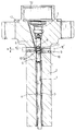
- The system according to the present invention will be described in detail and by way of example with reference to the accompanying drawing, which shows the body and plunger of an electromagnetic fuel injector, the displacement of which is determined using the system according to the present invention.
- Though, as already stated, the system according to the present invention is suitable for determining axial displacement of any type of rod forming part of any type of device, in the following description, the system will be described as employed for determining the displacement of plunger 1 inside body 2 of an electromagnetic fuel injector.
- Said plunger 1 slides inside a
seat 3 substantially consisting of an axial hole formed inside body 2. As the bottom of plunger 1 (not shown) provides for closing one or more injection orifices in the injector nozzle, plunger 1 normally travels between a closed position, wherein said injection orifices are closed, and an open position, wherein fuel is allowed to flow through said orifices. - The injector itself presents two
chambers seat 3, and the second formed above plunger 1 and coaxial withchamber 4. -
Chamber 4 normally contains pressurized fuel for injection through said injection orifices, whereaschamber 5 contains further pressurized fuel and acts as a control chamber on the injector. Plunger 1 is raised automatically in known manner when the pressure insidecontrol chamber 5 is lowered by means of an electromagnetic valve, and the resulting pressure exerted on plunger 1 causes it to move upwards. - For determining displacement of plunger 1 according to the present invention, a sliding coupling for plunger 1 is provided between
portion 6 of the same and the surface ofseat 3. Saidportion 6 separateschambers seat 3, while at the same time substantially preventing fuel leakage fromchambers - According to the present invention, said
portion 6 of plunger 1 presents two annular grooves 7 and 8 defining an annular surface portion 9, as shown clearly in the drawing. The system according to the present invention also consists in forming on body 2 at least a housing communicating withseat 3, and in providing inside said housing a proximity transducer 10' for determining displacement of said annular surface portion 9. - Each
housing 10 may consist simply of a hole having its axis perpendicular to that ofseat 3. As shown in the accompanying drawing, a pair ofhousings 10 may conveniently be provided for respective proximity transducers 10' separated in the direction of the plunger axis. The distance between the axes of said holes is indicated "a" in the accompanying drawing. - Alternatively, instead of one pair, provision may be made for two pairs of
housings 10 for respective proximity transducers, the housings in each said pair being separated in the direction of the plunger axis. - The annular cavities 11 formed between the surface of
seat 3 and annular grooves 7 and 8 ofportion 6 of plunger 1 communicate with each other and with adrain chamber 12 via aduct 13, so as to convey insidechamber 12 any fuel leaking fromchambers plunger portion 6 andseat 3. - Proximity transducers 10' inside
housings 10 may be of any known type, for determining displacement of annular surface portion 9, for example, as a function of a variation in capacity or magnetic flux. - The signals produced by transducers 10' may be supplied to any type of device capable of processing said signals in any manner, e.g. for indicating displacement of plunger 1, or the manner in which said displacement varies as a function of time. The system according to the present invention therefore provides for determining displacement of the rod both quickly and easily, and requires only straightforward mechanical machining of the injector components for forming annular grooves 7 and 8 and
holes 10. Moreover, said mechanical machining in no way affects the characteristics of the injector, which is in no way impaired by the rod displacement determining function, despite the rod operating in a high-pressure chamber of up to 2000 bar. - In particular, should the system according to the present invention feature, not one, but two transducers 10' as shown in the accompanying drawing, these may be connected in the known so-called half inductive bridge configuration to obtain a highly reliable signal, especially as regards thermal drift. Should member 2 feature two pairs of transducers 10', with the transducers in each pair separated in the direction of the rod axis, said transducers may be connected in the known so-called full inductive bridge configuration.
Claims (7)
- A system for determining axial displacement of a rod (1) included in a device comprising also a member (2) provided with at least two chambers (4, 5) for a high pressure fluid, said member (2) being provided with a seat (3) for said rod (1), each said chamber (4, 5) being defined by a corresponding surface portion of said rod (1) and said seat (3), said chambers (4, 5) being in communication through said seat (3), a sliding coupling being provided for said rod (1) between said seat (3) and a portion (6) of said rod (1) separating said chambers (4, 5); characterised by a pair of annular grooves (7, 8) provided on said portion (6) of said rod (1) and defining an annular surface portion (9); at least a housing (10) provided in said member (2) and communicating with said seat (3); and a proximity transducer (10') provided inside said housing (10) for determining displacement of said annular surface portion (9).
- A system as claimed in Claim 1, characterised in that a pair of said housings (10) are provided in said member (2) for housing respective proximity transducers (10') separated in the direction of said rod axis and connected in a "half inductive bridge" configuration.
- A system as claimed in Claim 1, characterised in that two pairs of said housings (10) are provided in said member (2) for housing respective proximity transducers (10'), the housings in each said pair being separated in the direction of said rod axis and connected in a "full inductive bridge" configuration.
- A system as claimed in one of the foregoing Claims, characterised in that an annular cavity (11) between said annular grooves (7, 8) of said rod (1) and said seat (3) communicates via a duct (13) with a drain chamber (12) for collecting any fluid leaking between the mating surfaces of said portion (6) and said seat (3).
- A system as claimed in one of the foregoing Claims, characterised in that said seat (3) for said rod (1) consists of an axial hole formed in said member (2), and each said housing (10) consists of a hole having its axis perpendicular to that of said axial hole forming said seat (3) and terminating inside said axial hole forming said seat (3).
- A system as claimed in Claim 5, characterised in that one of said chambers (4) is formed between said rod (1) and the surface of said hole forming said seat (3), while the other said chamber (5) consists of a cavity coaxial with said seat (3) and located above said rod (1).
- A system as claimed in one of the foregoing Claims, characterised in that said member (2) consists of the body of an electromagnetic fuel injection valve, and said rod (1) consists of a valve plunger.
Applications Claiming Priority (2)
| Application Number | Priority Date | Filing Date | Title |
|---|---|---|---|
| IT8967263A IT1232374B (en) | 1989-04-12 | 1989-04-12 | SYSTEM FOR DETERMINING THE MOVEMENT OF AN AUCTION IN THE DIRECTION OF ITS AXIS, IN PARTICULAR OF THE MOVABLE SHUTTER AUCTION OF AN ELECTROMAGNETICALLY OPERATED FUEL INJECTION DEVICE |
| IT6726389 | 1989-04-12 |
Publications (3)
| Publication Number | Publication Date |
|---|---|
| EP0392379A2 EP0392379A2 (en) | 1990-10-17 |
| EP0392379A3 EP0392379A3 (en) | 1991-11-21 |
| EP0392379B1 true EP0392379B1 (en) | 1994-07-20 |
Family
ID=11300961
Family Applications (1)
| Application Number | Title | Priority Date | Filing Date |
|---|---|---|---|
| EP90106608A Expired - Lifetime EP0392379B1 (en) | 1989-04-12 | 1990-04-06 | System for determining axial displacement of a rod, particularly the plunger of an electromagnetic fuel injector |
Country Status (7)
| Country | Link |
|---|---|
| US (1) | US5005404A (en) |
| EP (1) | EP0392379B1 (en) |
| JP (1) | JP2838724B2 (en) |
| BR (1) | BR9001738A (en) |
| DE (1) | DE69010730T2 (en) |
| ES (1) | ES2060844T3 (en) |
| IT (1) | IT1232374B (en) |
Families Citing this family (4)
| Publication number | Priority date | Publication date | Assignee | Title |
|---|---|---|---|---|
| US5738071A (en) * | 1991-05-22 | 1998-04-14 | Wolff Controls Corporation | Apparatus and method for sensing movement of fuel injector valve |
| US5747684A (en) * | 1996-07-26 | 1998-05-05 | Siemens Automotive Corporation | Method and apparatus for accurately determining opening and closing times for automotive fuel injectors |
| US5895844A (en) * | 1997-05-29 | 1999-04-20 | Outboard Marine Corporation | Precise fuel flow measurement with modified fluid control valve |
| GB2340610A (en) * | 1998-08-18 | 2000-02-23 | Lucas Ind Plc | Needle lift sensor |
Family Cites Families (8)
| Publication number | Priority date | Publication date | Assignee | Title |
|---|---|---|---|---|
| DE2305114A1 (en) * | 1973-02-02 | 1974-08-08 | Bosch Gmbh Robert | FUEL INJECTION NOZZLE FOR COMBUSTION MACHINES |
| FR2375461A1 (en) * | 1976-12-22 | 1978-07-21 | Souriau & Cie | INJECTOR NEEDLE LIFT SENSOR |
| FR2435608A1 (en) * | 1978-09-11 | 1980-04-04 | Monnet Francois | Fuel metering device for diesel engine injector - is electrically operated by needle valve giving easy adjustment |
| DE3004424A1 (en) * | 1980-02-07 | 1981-08-13 | Robert Bosch Gmbh, 7000 Stuttgart | FUEL INJECTOR HOLDER |
| JPS57176462A (en) * | 1981-04-24 | 1982-10-29 | Toshiba Corp | Microcomputer device |
| DE3326840A1 (en) * | 1983-07-26 | 1985-02-14 | Robert Bosch Gmbh, 7000 Stuttgart | FUEL INJECTION NOZZLE FOR INTERNAL COMBUSTION ENGINES |
| GB2170605B (en) * | 1985-02-06 | 1988-08-17 | Lucas Ind Plc | Transducers |
| JPS61267216A (en) * | 1985-05-20 | 1986-11-26 | オムロン株式会社 | Proximity switch |
-
1989
- 1989-04-12 IT IT8967263A patent/IT1232374B/en active
-
1990
- 1990-04-06 EP EP90106608A patent/EP0392379B1/en not_active Expired - Lifetime
- 1990-04-06 ES ES90106608T patent/ES2060844T3/en not_active Expired - Lifetime
- 1990-04-06 DE DE69010730T patent/DE69010730T2/en not_active Expired - Lifetime
- 1990-04-10 US US07/507,653 patent/US5005404A/en not_active Expired - Lifetime
- 1990-04-11 BR BR909001738A patent/BR9001738A/en unknown
- 1990-04-12 JP JP2097465A patent/JP2838724B2/en not_active Expired - Fee Related
Also Published As
| Publication number | Publication date |
|---|---|
| JPH02306104A (en) | 1990-12-19 |
| DE69010730D1 (en) | 1994-08-25 |
| IT1232374B (en) | 1992-01-28 |
| BR9001738A (en) | 1991-06-04 |
| US5005404A (en) | 1991-04-09 |
| JP2838724B2 (en) | 1998-12-16 |
| IT8967263A0 (en) | 1989-04-12 |
| ES2060844T3 (en) | 1994-12-01 |
| EP0392379A2 (en) | 1990-10-17 |
| DE69010730T2 (en) | 1995-01-05 |
| EP0392379A3 (en) | 1991-11-21 |
Similar Documents
| Publication | Publication Date | Title |
|---|---|---|
| US4679765A (en) | Low leakage orifice-controlled poppet valve | |
| EP1126203B1 (en) | Solenoid pilot operated valve | |
| US5556031A (en) | Fuel injection nozzle having a valve and a control element for controlling fuel pressure acting on a surface of the valve | |
| EP0385397B1 (en) | Diesel engine electromagnetic fuel injector | |
| JP3691877B2 (en) | solenoid valve | |
| US20080265190A1 (en) | Electromagnetic Pressure Regulating Valve Device Having an Integrated Pressure Sensor | |
| EP1302654B1 (en) | Internal combustion engine fuel injector | |
| EP0238201A3 (en) | Poppet valve assembly | |
| JPH07151261A (en) | Electromagnetic proportional pressure control valve | |
| US4962881A (en) | Flow passage coupling unit | |
| US4254653A (en) | Electromagnetic fuel injector calibration | |
| US5005404A (en) | System for determining axial displacement of a rod, particularly the plunger of an electromagnetic fuel injector | |
| US4292740A (en) | Self-actuated displacement transducer | |
| EP0369969B1 (en) | Valve for pressurized media | |
| US5000220A (en) | Metering valve with follow-up servo | |
| KR20010052202A (en) | Method for mounting a valve module of a fuel injector | |
| JPH0794845B2 (en) | Differential pressure actuator | |
| US5100102A (en) | Compact electronic fuel injector | |
| EP0486513B1 (en) | Calibration of fuel injectors via permeability adjustement | |
| US5495869A (en) | Changeover valve and flow control valve assembly having the same | |
| GB2253721A (en) | Pressure control valve | |
| KR950702023A (en) | FLOW TRANSDUCER | |
| JPS63208911A (en) | pressure control valve | |
| US5238018A (en) | Proportional pressure control valve | |
| JP3485992B2 (en) | Spool valve device |
Legal Events
| Date | Code | Title | Description |
|---|---|---|---|
| PUAI | Public reference made under article 153(3) epc to a published international application that has entered the european phase |
Free format text: ORIGINAL CODE: 0009012 |
|
| AK | Designated contracting states |
Kind code of ref document: A2 Designated state(s): DE ES FR GB SE |
|
| PUAL | Search report despatched |
Free format text: ORIGINAL CODE: 0009013 |
|
| AK | Designated contracting states |
Kind code of ref document: A3 Designated state(s): DE ES FR GB SE |
|
| 17P | Request for examination filed |
Effective date: 19920512 |
|
| RAP1 | Party data changed (applicant data changed or rights of an application transferred) |
Owner name: ELASIS SISTEMA RICERCA FIAT NEL MEZZOGIORNO SOCIET |
|
| 17Q | First examination report despatched |
Effective date: 19930211 |
|
| GRAA | (expected) grant |
Free format text: ORIGINAL CODE: 0009210 |
|
| AK | Designated contracting states |
Kind code of ref document: B1 Designated state(s): DE ES FR GB SE |
|
| REF | Corresponds to: |
Ref document number: 69010730 Country of ref document: DE Date of ref document: 19940825 |
|
| ET | Fr: translation filed | ||
| REG | Reference to a national code |
Ref country code: ES Ref legal event code: FG2A Ref document number: 2060844 Country of ref document: ES Kind code of ref document: T3 |
|
| EAL | Se: european patent in force in sweden |
Ref document number: 90106608.4 |
|
| PLBE | No opposition filed within time limit |
Free format text: ORIGINAL CODE: 0009261 |
|
| STAA | Information on the status of an ep patent application or granted ep patent |
Free format text: STATUS: NO OPPOSITION FILED WITHIN TIME LIMIT |
|
| 26N | No opposition filed | ||
| REG | Reference to a national code |
Ref country code: GB Ref legal event code: IF02 |
|
| PGFP | Annual fee paid to national office [announced via postgrant information from national office to epo] |
Ref country code: GB Payment date: 20020424 Year of fee payment: 13 |
|
| PGFP | Annual fee paid to national office [announced via postgrant information from national office to epo] |
Ref country code: SE Payment date: 20020426 Year of fee payment: 13 |
|
| PGFP | Annual fee paid to national office [announced via postgrant information from national office to epo] |
Ref country code: ES Payment date: 20020429 Year of fee payment: 13 |
|
| PGFP | Annual fee paid to national office [announced via postgrant information from national office to epo] |
Ref country code: FR Payment date: 20020430 Year of fee payment: 13 |
|
| REG | Reference to a national code |
Ref country code: FR Ref legal event code: TP |
|
| PG25 | Lapsed in a contracting state [announced via postgrant information from national office to epo] |
Ref country code: GB Free format text: LAPSE BECAUSE OF NON-PAYMENT OF DUE FEES Effective date: 20030406 |
|
| PG25 | Lapsed in a contracting state [announced via postgrant information from national office to epo] |
Ref country code: SE Free format text: LAPSE BECAUSE OF NON-PAYMENT OF DUE FEES Effective date: 20030407 Ref country code: ES Free format text: LAPSE BECAUSE OF NON-PAYMENT OF DUE FEES Effective date: 20030407 |
|
| GBPC | Gb: european patent ceased through non-payment of renewal fee |
Effective date: 20030406 |
|
| EUG | Se: european patent has lapsed | ||
| PG25 | Lapsed in a contracting state [announced via postgrant information from national office to epo] |
Ref country code: FR Free format text: LAPSE BECAUSE OF NON-PAYMENT OF DUE FEES Effective date: 20031231 |
|
| REG | Reference to a national code |
Ref country code: FR Ref legal event code: ST |
|
| REG | Reference to a national code |
Ref country code: ES Ref legal event code: FD2A Effective date: 20030407 |
|
| PGFP | Annual fee paid to national office [announced via postgrant information from national office to epo] |
Ref country code: DE Payment date: 20090626 Year of fee payment: 20 |
|
| PG25 | Lapsed in a contracting state [announced via postgrant information from national office to epo] |
Ref country code: DE Free format text: LAPSE BECAUSE OF EXPIRATION OF PROTECTION Effective date: 20100406 |