EP0392284B1 - Damper with variable damping characteristics - Google Patents
Damper with variable damping characteristics Download PDFInfo
- Publication number
- EP0392284B1 EP0392284B1 EP90106110A EP90106110A EP0392284B1 EP 0392284 B1 EP0392284 B1 EP 0392284B1 EP 90106110 A EP90106110 A EP 90106110A EP 90106110 A EP90106110 A EP 90106110A EP 0392284 B1 EP0392284 B1 EP 0392284B1
- Authority
- EP
- European Patent Office
- Prior art keywords
- shock absorber
- pressure
- valve
- bypass
- reacting
- Prior art date
- Legal status (The legal status is an assumption and is not a legal conclusion. Google has not performed a legal analysis and makes no representation as to the accuracy of the status listed.)
- Expired - Lifetime
Links
Images

Classifications
-
- F—MECHANICAL ENGINEERING; LIGHTING; HEATING; WEAPONS; BLASTING
- F16—ENGINEERING ELEMENTS AND UNITS; GENERAL MEASURES FOR PRODUCING AND MAINTAINING EFFECTIVE FUNCTIONING OF MACHINES OR INSTALLATIONS; THERMAL INSULATION IN GENERAL
- F16F—SPRINGS; SHOCK-ABSORBERS; MEANS FOR DAMPING VIBRATION
- F16F9/00—Springs, vibration-dampers, shock-absorbers, or similarly-constructed movement-dampers using a fluid or the equivalent as damping medium
- F16F9/32—Details
- F16F9/50—Special means providing automatic damping adjustment, i.e. self-adjustment of damping by particular sliding movements of a valve element, other than flexions or displacement of valve discs; Special means providing self-adjustment of spring characteristics
- F16F9/512—Means responsive to load action, i.e. static load on the damper or dynamic fluid pressure changes in the damper, e.g. due to changes in velocity
-
- F—MECHANICAL ENGINEERING; LIGHTING; HEATING; WEAPONS; BLASTING
- F16—ENGINEERING ELEMENTS AND UNITS; GENERAL MEASURES FOR PRODUCING AND MAINTAINING EFFECTIVE FUNCTIONING OF MACHINES OR INSTALLATIONS; THERMAL INSULATION IN GENERAL
- F16F—SPRINGS; SHOCK-ABSORBERS; MEANS FOR DAMPING VIBRATION
- F16F9/00—Springs, vibration-dampers, shock-absorbers, or similarly-constructed movement-dampers using a fluid or the equivalent as damping medium
- F16F9/32—Details
- F16F9/44—Means on or in the damper for manual or non-automatic adjustment; such means combined with temperature correction
- F16F9/46—Means on or in the damper for manual or non-automatic adjustment; such means combined with temperature correction allowing control from a distance, i.e. location of means for control input being remote from site of valves, e.g. on damper external wall
- F16F9/466—Throttling control, i.e. regulation of flow passage geometry
Abstract
Description
Die Erfindung berifft einen Stoßdämpfer mit veränderbarer Dämpfungscharakteristik, insbesondere für Kraftfahrzeuge, mit mindestens einem mit einem Dämpfungsmedium gefüllten Zylinder und einer Kolbenstange, die abgedichtet in den Zylinder eintaucht und die an ihrem zylinderseitigen Ende einen gegen die Zylinderwand abgedichteten Kolben trägt, der den Zylinderraum in zwei Kammern aufteilt, die durch einen Hauptstrom des Dämpfungsmediums miteinander verbunden sind, sowie mit einem aus wenigstens zwei zwischen den Kammern vorgesehenen, durch separat steuerbare Ventilkörper freigebbaren oder verschließbaren Bypass-Verbindungen bestehenden Bypass-System.The invention relates to a shock absorber with variable damping characteristics, in particular for motor vehicles, with at least one cylinder filled with a damping medium and a piston rod which plunges sealed into the cylinder and which carries at its cylinder-side end a piston which is sealed against the cylinder wall and which divides the cylinder space into two Divides chambers that are connected to each other by a main flow of the damping medium, and with a bypass system consisting of at least two bypass connections provided between the chambers, which can be released or closed by separately controllable valve bodies.
Ein derartiger Stoßdämpfer ist durch die DE-OS 36 05 182 bekanntgeworden.Such a shock absorber has become known from DE-OS 36 05 182.
Die der Erfindung zugrundeliegende Aufgabe besteht darin, die Dämpfungscharakteristik eines derartigen Stoßdämpfers weiter zu verfeinern bzw. praxisgerechter zu gestalten.The object on which the invention is based is to further refine the damping characteristic of such a shock absorber or to make it more practical.
Gemäß der Erfindung wird dies dadurch erreicht, daß jede der Bypass-Verbindungen mit einem druckabhängig reagierenden Ventil versehen ist, wobei die Ventile zu den jeweils zugeordneten steuerbaren Bypass-Verbindungen in Reihe geschaltet sind.According to the invention, this is achieved in that each of the bypass connections is provided with a pressure-responsive valve, the valves being connected in series with the respectively associated controllable bypass connections.
In Fortführung der Erfindung weist das druckabhängig reagierende Ventil einen für die Zug- und Druckstufe gemeinsamen, wechselseitig fedederbelasteten, druckbeaufschlagbaren Ventilkörper auf, welcher das Ventil sensibel reagieren und schnell ansprechen läßt.In continuation of the invention, the valve, which reacts as a function of pressure, has a valve body which is common to the rebound and compression stage and which can be acted upon by spring pressure and which can be acted upon by pressure, and which allows the valve to react sensitively and respond quickly.
Eine kompakte Bauweise des Ventils ist gemäß einer Ausgestaltung dadurch gewährleistet, daß der Ventilkörper zwischen den Endanschlägen zweier Federkörper auf einem Trägerbolzen des Ventils verschieblich gelagert ist.According to one embodiment, a compact design of the valve is ensured in that the valve body is displaceably mounted on a support bolt of the valve between the end stops of two spring bodies.
Eine gedrungene Bauweise des Bypass-Systems bei zwei Bypass-Verbindungen läßt sich nach einem weiteren Vorschlag dadurch realisieren, daß eins der druckabhängig reagierenden Ventile für die Druck- bzw. Zugstufe einen inneren federnden Ventilkörper bzw. einen konzentrisch dazu angeordneten äußeren federnden Ventilkörper aufweist. Eine bevorzugte konstruktive Ausgestaltung besteht darin, daß die druckabhängig reagierenden Ventile innerhalb der Kolbenstange in Reihe hintereinander angeordnet sind.According to a further proposal, a compact construction of the bypass system with two bypass connections can be realized in that one of the pressure-dependent valves for the compression or rebound stage has an inner resilient valve body or an outer resilient valve body arranged concentrically to it. A preferred design is that the pressure-responsive valves are arranged in series within the piston rod.
Zur Optimierung des Bypass-Systems wird außerdem vorgeschlagen, daß den druckabhängig reagierenden Ventilen unterschiedliche Strömungsquerschnitte der jeweils zugehörigen Bypass-Verbindung des Bypass-Systems zugeordnet sind, wobei zweckmäßigerweise dem zweiten der in Reihe geschalteten, druckabhängig reagierenden Ventile ein größerer Strömungsquerschnitt der zugehörigen Bypass-Verbindung zugeordnet ist.To optimize the bypass system, it is also proposed that the pressure-responsive valves are assigned different flow cross-sections of the respective bypass connection of the bypass system, expediently a larger flow cross-section of the associated bypass connection to the second of the series-connected, pressure-responsive valves assigned.
Der mit der Erfindung erzielte Vorteil besteht darin, daß insbesondere bei den zugeschalteten weicheren Dämpfungsstufen des Stoßdämpfers die Unterschiede in der Dämpfungskraft angehoben bzw. differenzierter wirksam werden, wobei die Dämpfungskraft insbesondere im Bereich kleiner Kolbengeschwindigkeiten des Stoßdämpfers angehoben wird.The advantage achieved by the invention is that the differences in the damping force are increased or more differentially effective, particularly in the case of the connected softer damping stages of the shock absorber, the damping force being increased particularly in the range of low piston speeds of the shock absorber.
Die Erfindung wird nachstehend anhand der in den beigefügten Abbildungen dargestellten Ausführungsbeispiele näher erläutert.The invention is explained in more detail below on the basis of the exemplary embodiments illustrated in the attached figures.
Hierbei zeigen:
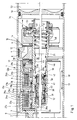
- Figur 1 einen im Längsschnitt in zwei Hälften in zwei unterschiedlichen Wirkstellungen dargestellten Stoßdämpfer gemäß Erfindung und
- Figur 2 eine Variante der Erfindung im Teillängsschnitt.
- Figure 1 is a longitudinal section in two halves in two different operative positions shown shock absorber according to the invention and
- Figure 2 shows a variant of the invention in partial longitudinal section.
In Figur 1 ist ein Teil eines Stoßdämpfers 1 ohne Befestigungselemente dargestellt. In einem rohrförmigen Zylinder 2 befindet sich eine teilweise im Anschnitt dargestellte Kolben-/Kolbenstangenanordnung 3 mit dem eigentlichen Kolben 4, einem Übergangsteil 6 zur Aufnahme von Erregerspulen, Steuerschiebern und Bypassen, und der eigentlichen Kolbenstange 7. Der Kolben 4, der mittels einer Ringdichtung 8 gegenüber dem Zylinder 2 abgedichtet ist, trennt zwei mit einem Dämpfungsmedium, zum Beispiel ÖI, gefüllte Kammern 9 und 11 voneinander. In dem Kolben 4 befindet sich ein Kanal 12 für den Hauptstrom des Dämpfungsmediums bei Zugbeanspruchung (Bewegung der Kolbenstange 7 in Richtung des Pfeils 13). Es können auch mehrere Kanäle 12 vorgesehen sein. Mit 14 ist ein als Ventil wirkender federnder Verschluß bezeichnet, der aus den Federscheiben 16 besteht. Ein entsprechender Kanal 17 (oder mehrere Kanäle) läßt den Hauptstrom bei Druckbelastung des Stoßdämpfers 1 (Bewegung der Kolbenstange 7 in Richtung des Pfeils 18) passieren. Mit 19 sind als Ventil wirkende Federscheiben vor dem Kanal 17 bezeichnet.In Figure 1, part of a shock absorber 1 is shown without fasteners. In a tubular cylinder 2 there is a piston /
Auf einem als Zylinder 21 ausgebildeten gemeinsamen Sitz befinden sich ringförmig geformte Steuerschieber 22a, 22b mit jeweils vier als Bypass-Verbindungen wirkenden Bohrungen 23a bzw. 23b, die um jeweils 90 gegeneinander versetzt sind. Die Steuerschieber 22a, 22b werden konzentrisch umgeben von zugeordneten Erregerspulen 24a bzw. 24b, deren Zuleitungen für den Erregerstrom mit 26 bezeichnet sind. Die Erregerspulen 24 sind umgeben von Ringen 27a, 27b aus ferromagnetischem Material. Bei Erregung einer Erregerspule 24a, 24b wird der zugeordnete Steuerschieber 22a bzw. 22b aus ferromagnetischem Material entgegen der Wirkung der Federn 28a bzw. 28b in die erregte Spule hineingezogen, wo seine Bohrungen 23a, 23b aus einer Sperrposition (bei Steuerschieber 22b dargestellt) in eine Durchlaßposition (bei Steuerschieber 22a dargestellt) bewegt werden. In Durchlaßposition fluchten dieOn a common seat designed as a
Bohrungen 23a, 23b mit Bohrungen 29a, 29b in dem Zylinder 21, so daß bei Zugbelastung (Bewegung der Kolbenstange 7 in Richtung des Pfeils 13) Dämpfungsmedium von der Kammer 9 in die Kammer 11 außer durch den Hauptstromkanal 12 auch durch den Bypass strömen kann, der in dem Beispiel realisiert ist durch radiale Bohrungen 31 a in einem äußeren Zylinder des Übergangsteils 6, durch die radialen Bohrungen 23a in dem Steuerschieber 22a, durch die radialen Bohrungen 29a in dem inneren Zylinder 21 und durch eine axiale Bohrung 32 in dem Zylinder 21. Bei Erregung der Spule 24b wird ein weiterer Bypass entsprechend geöffnet.Bores 23a, 23b with
Sowohl der ersten steuerbaren Bypass-Verbindung 23a als auch der zweiten steuerbaren Bypass-Verbindung 23b sind innerhalb der axialen Bohrung 32 jeweils in Reihe geschaltete bzw. innerhalb der Bohrung 32 in Reihe hintereinander angeordnete druckabhängig reagierende Ventile 33 bzw. 34 zugeordnet. Das der Bypass-Verbindung 23a nachgeschaltete Ventil 33 weist einen für die Zugstufe (Pfeil 13) sowie für die Druckstufe (Pfeil 18) gemeinsamen, wechselseitig federbelasteten, druckbeaufschlagbaren Ventilkörper 36 auf, der zwischen den Endanschlägen zweier durch Druckfedern 37 bzw. 38 beaufschlagbarer Federkörper 39 bzw. 41 auf einem Trägerbolzen 42 verschieblich gelagert ist.Both the first
Bei Öffnung bzw. Zuschaltung der Bypass-Verbindung 23a durch Betätigung des Steuerschiebers 22a wird durch das in die Bohrung 32 einströmende Dämpfungsmedium zunächst ein Vordruck in dem Ventil 33 aufgebaut, bis die Vorspannung des Federkörpers 41 überwunden und der Ventilkörper 36 in die rechte Anschlagposition verschoben wird. Dadurch kann das Dämpfungsmedium durch den zwischen dem Ventilkörper 36 und einem ortsfesten Ventilringsitz 43 gebildeten Ringspalt in den freien Querschnitt der Axialbohrung 32 und weiter über das noch zu beschreibende druckabhängig reagierende Ventil 34 in die Kammer 11 des Stoßdämpfers einströmen. Dieser Zustand ist durch den zur Hälfte dargestellten oberen Teil des Ventils 33 sowie durch die den Strömungsweg des Dämpfungsmediums anzeigende Pfeilkette 44 gemäß Figur 1 für die Zugstufe (Pfeil 13) des Stoßdämpfers 1 angedeutet.When the
In der Druckstufe (Pfeil 18) des Stoßdämpfers baut sich durch das zurückfließende Dämpfungsmedium zunächst auf der Gegenseite des Ventilkörpers 36 in der axialen Bohrung 32 ein Vordruck auf, welcher den Ventilkörper 36 gegen den Federkörper 39 bewegt und nach Überwindung der Vorspannung der Feder 37 den Ventilkörper 36 soweit nach links bewegt, daß zwischen diesem und dem ortsfesten Ventilringsitz 43 ein Durchtrittsspalt geöffnet wird. Bei dieser in der unteren Hälfte der Figur 1 dargestellten Betätigungsstellung eines Teils des Ventils 33 strömt das Dämpfungsmedium in Richtung der Pfeilkette 46 aus der Kammer 11 des Stoßdämpfers zurück in die Kammer 9.In the pressure stage (arrow 18) of the shock absorber, a back pressure builds up on the opposite side of the
Das der zweiten zuschaltbaren Bypass-Verbindung 23b zugeordnete druckabhängig reagierende Ventil 34 weist für die Druckstufe des Stoßdämpfers einen inneren federnden Ventilkörper 47 auf, der durch eine Druckfeder 48 gegen einen Ventilsitz 49 gedrückt wird. Für die Zugstufe des Stoßdämpfers ist das Ventil 34 mit einem konzentrisch zum inneren Ventilkörper 47 angeordneten äußeren federnden Ventilkörper 51 versehen, welcher ähnlich dem Ventilverschluß 14 des Kolbens 4 aus einer Federscheibe besteht. Bei Betätigung des Steuerschiebers 22b wird die zweite Bypass-Verbindung 23b geöffnet und damit die Dämpfungscharakteristik nochmals um eine Stufe weicher eingestellt, wobei sich durch die nunmehr vermehrt über die Bypass-Verbindung 23b in Richtung der Pfeilkette 44 fließende Gesamtmenge des Dämpfungsmediums unter dem Ventilkörper 51 des Ventils 34 ein entsprechender Vordruck aufbaut, bis der Ventilkörper 51 soweit öffnet, daß über den vergrößerten Durchtrittsquerschnitt die entsprechende Menge der Dämpfungsflüssigkeit ungehindert in die Kammer 11 fließen kann.The pressure-
Der Rückfluß der Dämpfungsflüssigkeit entlang der Pfeilkette 46 erfolgt entsprechend in der Druckstufe (Pfeil 18) des Stoßdämpfers nach Überwindung der Vorspannung der Feder 48 durch Abheben des inneren Ventilkörpers 47 von seinem Sitz 49, was in der unteren Hälfte der Figur 1 dargestellt ist.The backflow of the damping fluid along the
Durch die in den Strömungsweg 32 des Dämpfungsmediums eingefügten druckabhängig reagierenden Ventile 33 und 34 wird insbesondere bei niedrigeren Kolbengeschwindigkeiten des Stoßdämpfers die Dämpfungskraft durch die durch die Ventile 33 bzw. 34 in den entsprechenden Dämpfungsstufen erzeugten Vordrucke geringfügig angehoben.Due to the pressure-
Die Querschnitte der Bypass-Verbindungen 23a, 23b sind vorteilhaft unterschiedlich, so daß durch wahlweises Erregen einer der beiden oder beide Erregerspulen drei unterschiedliche Bypass-Ströme eingestellt werden können. Sind beide Erregerspulen entregt, so hat der Stoßdämpfer seine härteste Dämpfung, weil die Bypass-Ströme, die den Stoßdämpfer weicher machen, unterbrochen sind und das Dämpfungsmedium zwischen den Kammern 9 und 11 ausschließlich über den Kanal 12 bzw. den Kanal 17 des Kolbens 4 hin- und herströmen kann. Die schraffierten Teile 52a, 52b sind Distanzstücke mit nicht gezeigten Ausnehmungen, durch die das Dämpfungsmedium strömen kann.The cross sections of the
Bei Entregung der Erregerspulen 24a, 24b werden die zugehörigen Steuerschieber 22a bzw. 22b von den Federn 28a bzw. 28b in ihre Schließposition bewegt, wie anhand von Steuerschieber 22b dargestellt ist. In dieser Position fluchten die Bohrungen 23b und 29b nicht mehr miteinander, so daß der Strom durch den Bypass in dieser Position des Steuerschiebers 22b unterbrochen ist.When the
Auf der der Kolbenstange gegenüberliegenden Seite ist ein mit Druckgas gefüllter Raum 53 vorgesehen, der von dem Zylinder 2 und durch einen Trennkolben 54 begrenzt ist. Der Trennkolben dient dem Ausgleich unterschiedlicher Volumen der Kolbenstange 7 beim Eintritt in den Zylinder 2 und beim Austritt aus dem Zylinder 2.On the side opposite the piston rod, a
Bei der in Figur 2 dargestellten Variante des Stoßdämpfers sind Elemente, die denen der Figur 1 entsprechen, mit um hundert erhöhten Bezugszahlen versehen und nicht noch einmal besonders erläutert.In the variant of the shock absorber shown in FIG. 2, elements which correspond to those in FIG. 1 are provided with reference numbers increased by a hundred and are not explained again in particular.
Diese Variante unterscheidet sich lediglich dadurch vom zuvor beschriebenen Ausführungsbeispiel, daß den beiden steuerbaren Bypass-Verbindungen 123a und 123b gleichartige druckabhängig reagierende Ventile 133 bzw. 134 zugeordnet sind, welche in der axialen Bohrung 132 der Kolbenstange 107 in Reihe hintereinander angeordnet sind und lediglich in den Abmessungen ihrer Elemente bzw. ihrer steuerbaren Strömungsquerschnitte voneinander abweichen.This variant differs only from the previously described embodiment in that the two
Claims (7)
Applications Claiming Priority (2)
| Application Number | Priority Date | Filing Date | Title |
|---|---|---|---|
| DE3911819 | 1989-04-11 | ||
| DE3911819A DE3911819A1 (en) | 1989-04-11 | 1989-04-11 | SHOCK ABSORBER WITH CHANGEABLE DAMPING CHARACTERISTICS |
Publications (4)
| Publication Number | Publication Date |
|---|---|
| EP0392284A2 EP0392284A2 (en) | 1990-10-17 |
| EP0392284A3 EP0392284A3 (en) | 1991-04-10 |
| EP0392284B1 true EP0392284B1 (en) | 1994-08-10 |
| EP0392284B2 EP0392284B2 (en) | 1998-05-20 |
Family
ID=6378403
Family Applications (1)
| Application Number | Title | Priority Date | Filing Date |
|---|---|---|---|
| EP90106110A Expired - Lifetime EP0392284B2 (en) | 1989-04-11 | 1990-03-30 | Damper with variable damping characteristics |
Country Status (5)
| Country | Link |
|---|---|
| US (1) | US5094321A (en) |
| EP (1) | EP0392284B2 (en) |
| AT (1) | ATE109871T1 (en) |
| DE (2) | DE3911819A1 (en) |
| ES (1) | ES2058649T5 (en) |
Families Citing this family (13)
| Publication number | Priority date | Publication date | Assignee | Title |
|---|---|---|---|---|
| DE4033115C2 (en) * | 1990-10-18 | 1999-07-08 | Teves Gmbh Alfred | Adjustable vibration damper for motor vehicles |
| DE4033190C1 (en) * | 1990-10-19 | 1992-01-02 | Mercedes-Benz Aktiengesellschaft, 7000 Stuttgart, De | |
| US6102170A (en) * | 1998-05-07 | 2000-08-15 | Tenneco Automotive Inc. | Passive anti-roll system |
| US6588726B2 (en) * | 2001-07-13 | 2003-07-08 | Eaton Corporation | Load bearing solenoid operated valve and method of making same |
| AUPS228502A0 (en) * | 2002-05-13 | 2002-06-13 | Active Air Suspensions Ltd | Damper |
| DE10319390B4 (en) * | 2003-04-30 | 2005-11-10 | Thyssenkrupp Bilstein Gmbh | Hydraulic shock absorber |
| US20050029063A1 (en) * | 2003-07-24 | 2005-02-10 | Baltic Electronik Gmbh | Shock absorber having variable damping characteristics and method of damping vibrations with the shock absorber |
| JP5034074B2 (en) * | 2007-03-30 | 2012-09-26 | 日立オートモティブシステムズ株式会社 | Damping force adjustable fluid pressure shock absorber |
| US7878311B2 (en) * | 2007-07-19 | 2011-02-01 | Husco Automotive Holdings, LLC | Piston with an integral electrically operated adjustment valve for a hydraulic vibration damper |
| US7828126B2 (en) * | 2007-09-13 | 2010-11-09 | Bwi Company Limited S.A. | Magnetorheological (MR) piston, MR piston assembly, and MR damper system |
| US9056650B2 (en) * | 2009-06-15 | 2015-06-16 | Trek Bicycle Corporation | Bicycle shock assemblies with plunger operated valve arrangement |
| JP6454536B2 (en) * | 2014-03-31 | 2019-01-16 | 株式会社ショーワ | Shock absorber |
| US10393210B2 (en) | 2016-11-18 | 2019-08-27 | Beijingwest Industries Co., Ltd. | Dual mode hydraulic damper |
Family Cites Families (19)
| Publication number | Priority date | Publication date | Assignee | Title |
|---|---|---|---|---|
| US3896908A (en) * | 1973-05-04 | 1975-07-29 | Triple S Ind Inc | Shock absorbing apparatus |
| US3979134A (en) * | 1974-05-02 | 1976-09-07 | Monroe Belgium N.V. | Vehicle suspension system |
| GB2126687B (en) * | 1982-07-14 | 1986-08-20 | Tokico Ltd | Hydraulic damper with adjustable damping force |
| DE8336759U1 (en) * | 1983-04-11 | 1985-11-28 | F & O Electronic Systems GmbH & Co, 6901 Neckarsteinach | Shock absorbers with adjustable damping characteristics |
| DE3434877A1 (en) * | 1984-09-22 | 1986-04-17 | Boge Gmbh, 5208 Eitorf | HYDRAULIC, ADJUSTABLE SHOCK ABSORBER |
| DE3446133A1 (en) * | 1984-12-18 | 1986-06-19 | Fichtel & Sachs Ag, 8720 Schweinfurt | VIBRATION DAMPER WITH VARIABLE DAMPING FORCE |
| DE3518327A1 (en) * | 1985-05-22 | 1986-11-27 | Boge Gmbh, 5208 Eitorf | HYDRAULIC, ADJUSTABLE VIBRATION DAMPER |
| DE3601616A1 (en) * | 1986-01-21 | 1987-07-23 | Boge Gmbh | HYDROPNEUMATIC SUSPENSION WITH A DAMPING FORCE CONTROL |
| DE3768968D1 (en) * | 1986-01-30 | 1991-05-08 | Toyota Motor Co Ltd | CONTROL METHOD FOR VEHICLE BEHAVIOR. |
| DE3605182C2 (en) * | 1986-02-19 | 1995-02-23 | Hauni Werke Koerber & Co Kg | Shock absorber with variable damping characteristics |
| DE3608738C2 (en) * | 1986-03-15 | 1993-10-21 | Fichtel & Sachs Ag | Hydraulic vibration damper with adjustable damping force |
| EP0241677B1 (en) * | 1986-04-12 | 1990-05-02 | Körber Ag | Damper with adjustable damping characteristics |
| CA1263414A (en) * | 1986-06-05 | 1989-11-28 | Magnus Lizell | Restriction valve device for hydraulic pressure fluids in vehicle shock absorbing mechanisms |
| DE3644447A1 (en) * | 1986-12-24 | 1988-07-07 | Bosch Gmbh Robert | DEVICE FOR DAMPING MOTION PROCESSES |
| DE3832625C2 (en) * | 1987-10-13 | 1999-06-24 | Hauni Werke Koerber & Co Kg | Vibration damper with variable damping characteristics |
| JPH01234634A (en) * | 1987-11-30 | 1989-09-19 | Kayaba Ind Co Ltd | Damping force adjusting type shock absorber |
| JP2870643B2 (en) * | 1988-04-06 | 1999-03-17 | カヤバ工業株式会社 | Damping force adjustable shock absorber |
| JP2639396B2 (en) * | 1988-07-11 | 1997-08-13 | ダイムラー―ベンツ・アクチエンゲゼルシヤフト | Hydraulic telescopic shock absorber |
| DE3827538A1 (en) * | 1988-08-13 | 1990-02-15 | Bosch Gmbh Robert | DEVICE FOR DAMPING SPRING WHEEL SUSPENSION SYSTEMS IN VEHICLES |
-
1989
- 1989-04-11 DE DE3911819A patent/DE3911819A1/en not_active Ceased
-
1990
- 1990-03-30 EP EP90106110A patent/EP0392284B2/en not_active Expired - Lifetime
- 1990-03-30 ES ES90106110T patent/ES2058649T5/en not_active Expired - Lifetime
- 1990-03-30 AT AT90106110T patent/ATE109871T1/en not_active IP Right Cessation
- 1990-03-30 DE DE59006736T patent/DE59006736D1/en not_active Expired - Fee Related
- 1990-04-11 US US07/507,996 patent/US5094321A/en not_active Expired - Fee Related
Also Published As
| Publication number | Publication date |
|---|---|
| EP0392284A3 (en) | 1991-04-10 |
| DE3911819A1 (en) | 1990-10-18 |
| DE59006736D1 (en) | 1994-09-15 |
| ATE109871T1 (en) | 1994-08-15 |
| ES2058649T3 (en) | 1994-11-01 |
| EP0392284B2 (en) | 1998-05-20 |
| US5094321A (en) | 1992-03-10 |
| EP0392284A2 (en) | 1990-10-17 |
| ES2058649T5 (en) | 1998-09-16 |
Similar Documents
| Publication | Publication Date | Title |
|---|---|---|
| DE3832625C2 (en) | Vibration damper with variable damping characteristics | |
| DE10257872B4 (en) | Hydraulic shock absorber with damping force control | |
| DE3434033C2 (en) | ||
| EP0325958B1 (en) | Hydraulically actuated valve | |
| DE19711293C2 (en) | Hydraulic vibration damper with adjustable damping force | |
| EP0392284B1 (en) | Damper with variable damping characteristics | |
| EP0435357B1 (en) | Bypass valve with variable characteristics for adjustable vibration damper | |
| DE3609862A1 (en) | ADJUSTABLE SHOCK ABSORBER | |
| DE4241151C2 (en) | Hydraulic vibration damper with adjustable damping force | |
| EP1767811B1 (en) | Shock absorber with a damping force depending on the amplitude | |
| DE60133246T2 (en) | Solenoid valve stepless adjustable shock absorber | |
| EP1879668B1 (en) | Explosion protection valve | |
| EP1500845B1 (en) | Shock absorber with variable damping characteristics | |
| DE2548308C3 (en) | Valve arrangement with a first and a second coaxial valve | |
| DE19963415A1 (en) | Damping force regulating type hydraulic shock absorber | |
| EP0100973B1 (en) | Proportional hydraulic valve for precision control | |
| DE3119101A1 (en) | "WAY VALVE" | |
| DE3204112C2 (en) | Servo slide valve | |
| EP1657470A1 (en) | Hydropneumatic spring for vehicle, especially tracked vehicle | |
| EP0222858B2 (en) | Pipe cut-off device | |
| DE19908606C1 (en) | Hydraulic suspension damper for motor vehicle has flow openings in cylinder inner wall connected to annular outer volume | |
| DE3048814C2 (en) | ||
| EP0500534B1 (en) | Adjustable shock-absorber | |
| WO2022106088A1 (en) | Hydraulic shock absorber | |
| DE4423526C1 (en) | Vibration damper with adjustable damping force |
Legal Events
| Date | Code | Title | Description |
|---|---|---|---|
| PUAI | Public reference made under article 153(3) epc to a published international application that has entered the european phase |
Free format text: ORIGINAL CODE: 0009012 |
|
| AK | Designated contracting states |
Kind code of ref document: A2 Designated state(s): AT BE CH DE ES FR GB IT LI NL SE |
|
| PUAL | Search report despatched |
Free format text: ORIGINAL CODE: 0009013 |
|
| AK | Designated contracting states |
Kind code of ref document: A3 Designated state(s): AT BE CH DE ES FR GB IT LI NL SE |
|
| 17P | Request for examination filed |
Effective date: 19910919 |
|
| 17Q | First examination report despatched |
Effective date: 19930305 |
|
| GRAA | (expected) grant |
Free format text: ORIGINAL CODE: 0009210 |
|
| ITF | It: translation for a ep patent filed |
Owner name: DE DOMINICIS & MAYER S.R.L. |
|
| AK | Designated contracting states |
Kind code of ref document: B1 Designated state(s): AT BE CH DE ES FR GB IT LI NL SE |
|
| REF | Corresponds to: |
Ref document number: 109871 Country of ref document: AT Date of ref document: 19940815 Kind code of ref document: T |
|
| REF | Corresponds to: |
Ref document number: 59006736 Country of ref document: DE Date of ref document: 19940915 |
|
| GBT | Gb: translation of ep patent filed (gb section 77(6)(a)/1977) |
Effective date: 19940825 |
|
| ET | Fr: translation filed | ||
| PG25 | Lapsed in a contracting state [announced via postgrant information from national office to epo] |
Ref country code: SE Effective date: 19941110 |
|
| PLBI | Opposition filed |
Free format text: ORIGINAL CODE: 0009260 |
|
| 26 | Opposition filed |
Opponent name: FICHTEL & SACHS AG Effective date: 19950505 |
|
| REG | Reference to a national code |
Ref country code: CH Ref legal event code: PUE Owner name: HAUNI MASCHINENBAU AKTIENGESELLSCHAFT |
|
| NLR1 | Nl: opposition has been filed with the epo |
Opponent name: FICHTEL & SACHS AG |
|
| RAP2 | Party data changed (patent owner data changed or rights of a patent transferred) |
Owner name: HAUNI MASCHINENBAU AKTIENGESELLSCHAFT |
|
| REG | Reference to a national code |
Ref country code: FR Ref legal event code: TP |
|
| REG | Reference to a national code |
Ref country code: FR Ref legal event code: TP |
|
| NLT2 | Nl: modifications (of names), taken from the european patent patent bulletin |
Owner name: HAUNI MASCHINENBAU AKTIENGESELLSCHAFT |
|
| REG | Reference to a national code |
Ref country code: ES Ref legal event code: PC2A Owner name: HAUNI MASCHINENBAU AG. |
|
| NLS | Nl: assignments of ep-patents |
Owner name: HAUNI MASCHINENBAU AKTIENGESELLSCHAFT |
|
| REG | Reference to a national code |
Ref country code: GB Ref legal event code: 732E |
|
| PLAW | Interlocutory decision in opposition |
Free format text: ORIGINAL CODE: EPIDOS IDOP |
|
| PLAW | Interlocutory decision in opposition |
Free format text: ORIGINAL CODE: EPIDOS IDOP |
|
| PLAB | Opposition data, opponent's data or that of the opponent's representative modified |
Free format text: ORIGINAL CODE: 0009299OPPO |
|
| PUAH | Patent maintained in amended form |
Free format text: ORIGINAL CODE: 0009272 |
|
| STAA | Information on the status of an ep patent application or granted ep patent |
Free format text: STATUS: PATENT MAINTAINED AS AMENDED |
|
| R26 | Opposition filed (corrected) |
Opponent name: MANNESMANN SACHS AKTIENGESELLSCHAFT Effective date: 19950505 |
|
| 27A | Patent maintained in amended form |
Effective date: 19980520 |
|
| AK | Designated contracting states |
Kind code of ref document: B2 Designated state(s): AT BE CH DE ES FR GB IT LI NL SE |
|
| REG | Reference to a national code |
Ref country code: CH Ref legal event code: AEN Free format text: AUFRECHTERHALTUNG DES PATENTES IN GEAENDERTER FORM |
|
| NLR1 | Nl: opposition has been filed with the epo |
Opponent name: MANNESMANN SACHS AKTIENGESELLSCHAFT |
|
| ET3 | Fr: translation filed ** decision concerning opposition | ||
| NLR2 | Nl: decision of opposition | ||
| NLR3 | Nl: receipt of modified translations in the netherlands language after an opposition procedure | ||
| ITF | It: translation for a ep patent filed |
Owner name: DE DOMINICIS & MAYER S.R.L. |
|
| REG | Reference to a national code |
Ref country code: ES Ref legal event code: DC2A Kind code of ref document: T5 Effective date: 19980716 |
|
| GBTA | Gb: translation of amended ep patent filed (gb section 77(6)(b)/1977) | ||
| REG | Reference to a national code |
Ref country code: GB Ref legal event code: IF02 |
|
| PGFP | Annual fee paid to national office [announced via postgrant information from national office to epo] |
Ref country code: CH Payment date: 20020405 Year of fee payment: 13 |
|
| PGFP | Annual fee paid to national office [announced via postgrant information from national office to epo] |
Ref country code: AT Payment date: 20030321 Year of fee payment: 14 |
|
| PG25 | Lapsed in a contracting state [announced via postgrant information from national office to epo] |
Ref country code: LI Free format text: LAPSE BECAUSE OF NON-PAYMENT OF DUE FEES Effective date: 20030331 Ref country code: CH Free format text: LAPSE BECAUSE OF NON-PAYMENT OF DUE FEES Effective date: 20030331 |
|
| REG | Reference to a national code |
Ref country code: CH Ref legal event code: PL |
|
| PGFP | Annual fee paid to national office [announced via postgrant information from national office to epo] |
Ref country code: ES Payment date: 20040220 Year of fee payment: 15 |
|
| PGFP | Annual fee paid to national office [announced via postgrant information from national office to epo] |
Ref country code: GB Payment date: 20040227 Year of fee payment: 15 |
|
| PGFP | Annual fee paid to national office [announced via postgrant information from national office to epo] |
Ref country code: FR Payment date: 20040322 Year of fee payment: 15 |
|
| PGFP | Annual fee paid to national office [announced via postgrant information from national office to epo] |
Ref country code: NL Payment date: 20040323 Year of fee payment: 15 Ref country code: BE Payment date: 20040323 Year of fee payment: 15 |
|
| PG25 | Lapsed in a contracting state [announced via postgrant information from national office to epo] |
Ref country code: AT Free format text: LAPSE BECAUSE OF NON-PAYMENT OF DUE FEES Effective date: 20040330 |
|
| PGFP | Annual fee paid to national office [announced via postgrant information from national office to epo] |
Ref country code: DE Payment date: 20040413 Year of fee payment: 15 |
|
| PG25 | Lapsed in a contracting state [announced via postgrant information from national office to epo] |
Ref country code: IT Free format text: LAPSE BECAUSE OF NON-PAYMENT OF DUE FEES;WARNING: LAPSES OF ITALIAN PATENTS WITH EFFECTIVE DATE BEFORE 2007 MAY HAVE OCCURRED AT ANY TIME BEFORE 2007. THE CORRECT EFFECTIVE DATE MAY BE DIFFERENT FROM THE ONE RECORDED. Effective date: 20050330 Ref country code: GB Free format text: LAPSE BECAUSE OF NON-PAYMENT OF DUE FEES Effective date: 20050330 |
|
| PG25 | Lapsed in a contracting state [announced via postgrant information from national office to epo] |
Ref country code: ES Free format text: LAPSE BECAUSE OF NON-PAYMENT OF DUE FEES Effective date: 20050331 Ref country code: BE Free format text: LAPSE BECAUSE OF NON-PAYMENT OF DUE FEES Effective date: 20050331 |
|
| BERE | Be: lapsed |
Owner name: *HAUNI MASCHINENBAU A.G. Effective date: 20050331 |
|
| PG25 | Lapsed in a contracting state [announced via postgrant information from national office to epo] |
Ref country code: NL Free format text: LAPSE BECAUSE OF NON-PAYMENT OF DUE FEES Effective date: 20051001 Ref country code: DE Free format text: LAPSE BECAUSE OF NON-PAYMENT OF DUE FEES Effective date: 20051001 |
|
| GBPC | Gb: european patent ceased through non-payment of renewal fee |
Effective date: 20050330 |
|
| PG25 | Lapsed in a contracting state [announced via postgrant information from national office to epo] |
Ref country code: FR Free format text: LAPSE BECAUSE OF NON-PAYMENT OF DUE FEES Effective date: 20051130 |
|
| NLV4 | Nl: lapsed or anulled due to non-payment of the annual fee |
Effective date: 20051001 |
|
| REG | Reference to a national code |
Ref country code: FR Ref legal event code: ST Effective date: 20051130 |
|
| REG | Reference to a national code |
Ref country code: ES Ref legal event code: FD2A Effective date: 20050331 |
|
| BERE | Be: lapsed |
Owner name: *HAUNI MASCHINENBAU A.G. Effective date: 20050331 |