EP0391580A2 - A solvent responsive signal-carrying device - Google Patents
A solvent responsive signal-carrying device Download PDFInfo
- Publication number
- EP0391580A2 EP0391580A2 EP90303107A EP90303107A EP0391580A2 EP 0391580 A2 EP0391580 A2 EP 0391580A2 EP 90303107 A EP90303107 A EP 90303107A EP 90303107 A EP90303107 A EP 90303107A EP 0391580 A2 EP0391580 A2 EP 0391580A2
- Authority
- EP
- European Patent Office
- Prior art keywords
- conductive
- conductors
- solvent
- conductive material
- carrier medium
- Prior art date
- Legal status (The legal status is an assumption and is not a legal conclusion. Google has not performed a legal analysis and makes no representation as to the accuracy of the status listed.)
- Granted
Links
Images

Classifications
-
- G—PHYSICS
- G01—MEASURING; TESTING
- G01R—MEASURING ELECTRIC VARIABLES; MEASURING MAGNETIC VARIABLES
- G01R31/00—Arrangements for testing electric properties; Arrangements for locating electric faults; Arrangements for electrical testing characterised by what is being tested not provided for elsewhere
- G01R31/08—Locating faults in cables, transmission lines, or networks
- G01R31/081—Locating faults in cables, transmission lines, or networks according to type of conductors
- G01R31/083—Locating faults in cables, transmission lines, or networks according to type of conductors in cables, e.g. underground
-
- G—PHYSICS
- G01—MEASURING; TESTING
- G01M—TESTING STATIC OR DYNAMIC BALANCE OF MACHINES OR STRUCTURES; TESTING OF STRUCTURES OR APPARATUS, NOT OTHERWISE PROVIDED FOR
- G01M3/00—Investigating fluid-tightness of structures
- G01M3/02—Investigating fluid-tightness of structures by using fluid or vacuum
- G01M3/04—Investigating fluid-tightness of structures by using fluid or vacuum by detecting the presence of fluid at the leakage point
- G01M3/042—Investigating fluid-tightness of structures by using fluid or vacuum by detecting the presence of fluid at the leakage point by using materials which expand, contract, disintegrate, or decompose in contact with a fluid
- G01M3/045—Investigating fluid-tightness of structures by using fluid or vacuum by detecting the presence of fluid at the leakage point by using materials which expand, contract, disintegrate, or decompose in contact with a fluid with electrical detection means
-
- G—PHYSICS
- G01—MEASURING; TESTING
- G01M—TESTING STATIC OR DYNAMIC BALANCE OF MACHINES OR STRUCTURES; TESTING OF STRUCTURES OR APPARATUS, NOT OTHERWISE PROVIDED FOR
- G01M3/00—Investigating fluid-tightness of structures
- G01M3/02—Investigating fluid-tightness of structures by using fluid or vacuum
- G01M3/04—Investigating fluid-tightness of structures by using fluid or vacuum by detecting the presence of fluid at the leakage point
- G01M3/16—Investigating fluid-tightness of structures by using fluid or vacuum by detecting the presence of fluid at the leakage point using electric detection means
- G01M3/18—Investigating fluid-tightness of structures by using fluid or vacuum by detecting the presence of fluid at the leakage point using electric detection means for pipes, cables or tubes; for pipe joints or seals; for valves; for welds; for containers, e.g. radiators
-
- G—PHYSICS
- G08—SIGNALLING
- G08B—SIGNALLING SYSTEMS, e.g. PERSONAL CALLING SYSTEMS; ORDER TELEGRAPHS; ALARM SYSTEMS
- G08B21/00—Alarms responsive to a single specified undesired or abnormal condition and not otherwise provided for
- G08B21/18—Status alarms
- G08B21/20—Status alarms responsive to moisture
Definitions
- This invention relates to a signal-carrying device, in particular for a security or detector system, which is responsive to the presence of a solvent.
- the invention is applicable, in one sense, to a signal-carrying cable provided with a security system which is designed to protect against interference with the cable.
- the invention is applicable, in another sense, to a fluid-containing system, such for example an oil pipeline, having a sensor for sensing leakage of the fluid from the container.
- a signal-carrying device for a security or detector system comprising a conductor extending along a non-conductive surface, said conductor being composed of particulate conductive material held in a carrier medium which is soluble in at least one solvent, such that when the carrier medium is contacted by a said solvent, it will release conductive material therefrom sufficient to interrupt the conductive path through the conductive material.
- the present invention provides a signal-carrying device for a security or detector system comprising at least two conductors extending along a non-conductive surface in side-by-side spaced apart relationship, at least one of said conductors being formed of particulate conductive material held in a carrier medium which is soluble in at least one solvent, such that when the carrier medium is contacted by a said solvent, it will release conductive material therefrom sufficient to interrupt the conductive path through the conductive material and/or form a short circuit between said two conductors.
- the present invention provides a signal-carrying device for a security or detector system comprising at least two conductors extending in spaced-apart side-by-side relationship and insulated from each other by non-conductive material, a layer containing conductive material in a non-conductive carrier medium so printed over, or otherwise applied over, said conductors that the said conductors are not thereby electrically short circuited, the non-conductive carrier medium being soluble in a solvent such that when said solvent is applied to the layer the non-conductive carrier will dissolve and permit the conductive material to migrate between said conductors and short circuit therebetween.
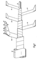
- the security cable shown in Figure 1 forms the subject of our copending patent application No. 8727092 to which attention is directed for a detailed explanation.
- a core 10 is over-wrapped by alternating layers 11,12 of conductive tape and insulating tape 13,14.
- a fifth layer 15 can be wrapped which comprises conductive strips 16 embedded in a layer of insulating material 17.
- the conductive layers are of a fibrous nature such that, when penetrated by a sharp instrument, conductive fibres will be carried through the intervening insulating layer and cause short-circuiting between adjacent conductive strip, and this short-circuiting can be detected by sensing apparatus connected at a selected position on the cable.
- This cable as shown, is enclosed within a jacket 18 which will be bonded to the outermost layer by a suitable adhesive.
- the outermost layer 15 of the cable which in this case is a composite layer of conductive strips 16 embedded in plastics material 17, is coated with a printed conductive coating 19.
- This coating comprises a plurality of parallel-spaced lines 20 printed in conductive ink so that they form an electrically- conductive path which can carry a signal.
- the conductive ink used to form the coating comprises a conductive filler carried in a carrier medium which is soluble in one or more solvents such that if this coating is contacted by such a solvent, one or more of the printed lines will dissolve or go into suspension.
- a tape or film of non-conductive material bearing conductive strips, printed from the material described above, can be wrapped around or otherwise applied to the outside of a liquid container such as a tank or pipeline, to detect leakage of liquid from the container.
- the printed film will be printed by use of a conductive ink of which the carrier component is soluble in the liquid contained within the container.
- a tape or film of non-conductive material along which conductors extend in parallel-spaced relationship, (the conductors having been printed or otherwise formed) is covered with a layer of carrier medium free from conductive material, so that it forms a thin insulating layer over the conductors.
- a conductive layer is then printed over the insulating layer using the conductive ink.
- the conductive layer can be an uninterrupted layer or printed in a pattern of lines or dots or in a random pattern. In the event of a solvent coming into contact with the printed layer it will dissolve through this layer and the insulating layer beneath it and allow conductive particles of the ink to migrate into contact with the conductors and produce short circuiting between adjacent conductors.
- a tape or film of non-conductive material along which conductors extend in parallel-spaced relationship is overprinted with the above-described conductive ink.
- the ink is applied so that it does not short circuit the conductors but such that upon contact with a said solvent, conductive material will be released from, or will migrate from, the ink to short circuit adjacent conductors.
- the ink can be printed in a series of dots superimposed on the conductors and insulation such that the dot diameter is less than the insulation spacing the conductors.
- the conductive printing material can comprise a particulate conductive material or filler, such as graphite, or other carbon, or a mixture thereof, and in particular is known as carbon black and foliac graphite.
- the conductive material will be carried in a carrier medium which is soluble in at least one solvent, and preferably in a wide range of solvents.
- the carrier medium can be a short chain polyester resin such as that sold under reference No. 49001 by Dupont.
- a solvent is added such as acetone.
- the ink is preferably applied to a tape or film of insulating material, such as a membrane of expanded polytetrafluoroethylene, for example that sold under the registered trade mark GORE-TEX by W. L. Gore & Associates, Inc.
- the ink can be printed by conventional transfer printing methods on to a tape or film to which conductive terminal elements had already been attached.
- the ink can be applied in straight parallel- spaced lines or in any other selected pattern from a roller or wheel on which the pattern had been etched.
- the lower part of the roller is arranged in a bath containing the ink, and the film to be printed is caused to move in contact with the top of the roller so that ink is picked up from the bath and transferred to the film.
Landscapes
- General Physics & Mathematics (AREA)
- Physics & Mathematics (AREA)
- Business, Economics & Management (AREA)
- Emergency Management (AREA)
- Examining Or Testing Airtightness (AREA)
- Investigating Or Analyzing Materials By The Use Of Electric Means (AREA)
- Centrifugal Separators (AREA)
- Cookers (AREA)
- Toys (AREA)
- Organic Low-Molecular-Weight Compounds And Preparation Thereof (AREA)
- Photoreceptors In Electrophotography (AREA)
- Conductive Materials (AREA)
- Communication Cables (AREA)
- Burglar Alarm Systems (AREA)
Abstract
Description
- This invention relates to a signal-carrying device, in particular for a security or detector system, which is responsive to the presence of a solvent.
- The invention is applicable, in one sense, to a signal-carrying cable provided with a security system which is designed to protect against interference with the cable. The invention is applicable, in another sense, to a fluid-containing system, such for example an oil pipeline, having a sensor for sensing leakage of the fluid from the container.
- The words 'conductor' and 'conductive' when used hereinafter should be read as including 'semi- conductor' or 'semi-conductive' whenever the context permits.
- According to the one aspect of the present invention there is provided a signal-carrying device for a security or detector system comprising a conductor extending along a non-conductive surface, said conductor being composed of particulate conductive material held in a carrier medium which is soluble in at least one solvent, such that when the carrier medium is contacted by a said solvent, it will release conductive material therefrom sufficient to interrupt the conductive path through the conductive material.
- According to another aspect, the present invention provides a signal-carrying device for a security or detector system comprising at least two conductors extending along a non-conductive surface in side-by-side spaced apart relationship, at least one of said conductors being formed of particulate conductive material held in a carrier medium which is soluble in at least one solvent, such that when the carrier medium is contacted by a said solvent, it will release conductive material therefrom sufficient to interrupt the conductive path through the conductive material and/or form a short circuit between said two conductors.
- According to a further aspect, the present invention provides a signal-carrying device for a security or detector system comprising at least two conductors extending in spaced-apart side-by-side relationship and insulated from each other by non-conductive material, a layer containing conductive material in a non-conductive carrier medium so printed over, or otherwise applied over, said conductors that the said conductors are not thereby electrically short circuited, the non-conductive carrier medium being soluble in a solvent such that when said solvent is applied to the layer the non-conductive carrier will dissolve and permit the conductive material to migrate between said conductors and short circuit therebetween.
- Some embodiments of the invention will now be particularly described, by way of example, with reference to the accompanying drawings in which:-
- Figure 1 is a diagrammatic illustration of the process of manufacture of a security cable.
- Figure 2 is a section through the completed cable showing a pattern of printed conductors beneath the jacket of the cable, and
- Figure 3 is a development of part of the cable of Figure 2.
- The security cable shown in Figure 1 forms the subject of our copending patent application No. 8727092 to which attention is directed for a detailed explanation. For the purpose of the present invention, it is sufficient to say that a
core 10 is over-wrapped byalternating layers 11,12 of conductive tape andinsulating tape fifth layer 15 can be wrapped which comprisesconductive strips 16 embedded in a layer ofinsulating material 17. The conductive layers are of a fibrous nature such that, when penetrated by a sharp instrument, conductive fibres will be carried through the intervening insulating layer and cause short-circuiting between adjacent conductive strip, and this short-circuiting can be detected by sensing apparatus connected at a selected position on the cable. - This cable, as shown, is enclosed within a
jacket 18 which will be bonded to the outermost layer by a suitable adhesive. - In accordance with the first embodiment of the invention shown in Figures 2 and 3, the
outermost layer 15 of the cable, which in this case is a composite layer ofconductive strips 16 embedded inplastics material 17, is coated with a printedconductive coating 19. This coating, as illustrated, comprises a plurality of parallel-spacedlines 20 printed in conductive ink so that they form an electrically- conductive path which can carry a signal. The conductive ink used to form the coating (and which is described in greater detail below) comprises a conductive filler carried in a carrier medium which is soluble in one or more solvents such that if this coating is contacted by such a solvent, one or more of the printed lines will dissolve or go into suspension. This will permit the conductive particles which it comprises to migrate and so interrupt the conductive path through the printed line or complete a short circuit with an adjacent printed line or between twoconductors 16. In this event, a signal passed through the printed lines orconductors 16 will be interrupted or otherwise varied, and this variation can be detected by a sensor connected at a selected position along the cable. - It will be apparent from this specific description of a cable that the invention can be utilised in a broader aspect.
- As a first example, a tape or film of non-conductive material bearing conductive strips, printed from the material described above, can be wrapped around or otherwise applied to the outside of a liquid container such as a tank or pipeline, to detect leakage of liquid from the container. The printed film will be printed by use of a conductive ink of which the carrier component is soluble in the liquid contained within the container.
- As a second example, a tape or film of non-conductive material along which conductors extend in parallel-spaced relationship, (the conductors having been printed or otherwise formed) is covered with a layer of carrier medium free from conductive material, so that it forms a thin insulating layer over the conductors. A conductive layer is then printed over the insulating layer using the conductive ink.
- The conductive layer can be an uninterrupted layer or printed in a pattern of lines or dots or in a random pattern. In the event of a solvent coming into contact with the printed layer it will dissolve through this layer and the insulating layer beneath it and allow conductive particles of the ink to migrate into contact with the conductors and produce short circuiting between adjacent conductors.
- As a third example, a tape or film of non-conductive material along which conductors extend in parallel-spaced relationship (the conductors having been printed or otherwise formed), is overprinted with the above-described conductive ink. The ink is applied so that it does not short circuit the conductors but such that upon contact with a said solvent, conductive material will be released from, or will migrate from, the ink to short circuit adjacent conductors. By way of example, the ink can be printed in a series of dots superimposed on the conductors and insulation such that the dot diameter is less than the insulation spacing the conductors.
- The conductive printing material, referred to herein as 'ink', can comprise a particulate conductive material or filler, such as graphite, or other carbon, or a mixture thereof, and in particular is known as carbon black and foliac graphite. The conductive material will be carried in a carrier medium which is soluble in at least one solvent, and preferably in a wide range of solvents. The carrier medium can be a short chain polyester resin such as that sold under reference No. 49001 by Dupont. In order that the mixture of the conductive filler and the carrier medium may be printed, a solvent is added such as acetone.
- The ink is preferably applied to a tape or film of insulating material, such as a membrane of expanded polytetrafluoroethylene, for example that sold under the registered trade mark GORE-TEX by W. L. Gore & Associates, Inc. The ink can be printed by conventional transfer printing methods on to a tape or film to which conductive terminal elements had already been attached. The ink can be applied in straight parallel- spaced lines or in any other selected pattern from a roller or wheel on which the pattern had been etched. The lower part of the roller is arranged in a bath containing the ink, and the film to be printed is caused to move in contact with the top of the roller so that ink is picked up from the bath and transferred to the film.
Claims (6)
Applications Claiming Priority (2)
| Application Number | Priority Date | Filing Date | Title |
|---|---|---|---|
| GB8907548 | 1989-04-04 | ||
| GB8907548A GB2230631B (en) | 1989-04-04 | 1989-04-04 | A solvent responsive signal-carrying device |
Publications (3)
| Publication Number | Publication Date |
|---|---|
| EP0391580A2 true EP0391580A2 (en) | 1990-10-10 |
| EP0391580A3 EP0391580A3 (en) | 1991-10-02 |
| EP0391580B1 EP0391580B1 (en) | 1995-10-04 |
Family
ID=10654423
Family Applications (1)
| Application Number | Title | Priority Date | Filing Date |
|---|---|---|---|
| EP90303107A Expired - Lifetime EP0391580B1 (en) | 1989-04-04 | 1990-03-22 | A solvent responsive signal-carrying device |
Country Status (10)
| Country | Link |
|---|---|
| US (1) | US5017908A (en) |
| EP (1) | EP0391580B1 (en) |
| JP (1) | JPH03102235A (en) |
| AT (1) | ATE128785T1 (en) |
| DE (1) | DE69022764T2 (en) |
| DK (1) | DK0391580T3 (en) |
| ES (1) | ES2080111T3 (en) |
| GB (1) | GB2230631B (en) |
| HK (1) | HK122693A (en) |
| SG (1) | SG105093G (en) |
Cited By (4)
| Publication number | Priority date | Publication date | Assignee | Title |
|---|---|---|---|---|
| WO2010062890A1 (en) * | 2008-11-26 | 2010-06-03 | Odyssian Technology Llc | Gaskets and seals with integrated leak detection capability |
| EP2299454A1 (en) | 2009-07-01 | 2011-03-23 | Nexans | Cable including means for detecting the presence of an electrically conducting body outside the cable |
| US8061211B1 (en) | 2009-06-19 | 2011-11-22 | Odyssian Technology, Llc | Seal with integrated sensor |
| WO2020249793A1 (en) * | 2019-06-12 | 2020-12-17 | M3S Industry Ltd | Device for monitoring the condition of a substrate and associated systems and methods |
Families Citing this family (10)
| Publication number | Priority date | Publication date | Assignee | Title |
|---|---|---|---|---|
| US5658277A (en) * | 1990-05-25 | 1997-08-19 | Novatec Medical Products, Inc. | Apparatus for electrical connection of glove monitor to patient |
| US5203202A (en) * | 1992-02-25 | 1993-04-20 | W. L. Gore & Associates, Inc. | Apparatus for detecting leaks in circuits |
| CA2210623A1 (en) * | 1995-01-17 | 1996-07-25 | W. L. Gore & Associates, Inc. | Method for making and using an improved durable printable sheet |
| US7015810B2 (en) * | 2003-12-02 | 2006-03-21 | Exon Science Incorporation | Control system with hot plug signal transmission channel for reaction equipment and monitoring device thereof |
| US9632275B2 (en) * | 2012-06-15 | 2017-04-25 | Commscope Technologies Llc | Secure jacket |
| JP6146901B2 (en) * | 2013-07-26 | 2017-06-14 | 矢崎エナジーシステム株式会社 | cable |
| KR101538507B1 (en) * | 2015-03-26 | 2015-07-23 | 플로우닉스 주식회사 | Leak sensor for side detection |
| JP6471075B2 (en) * | 2015-10-06 | 2019-02-13 | タツタ電線株式会社 | Cable and liquid detection member for cable |
| FR3066272B1 (en) * | 2017-05-12 | 2019-07-19 | Sasha Dabetic | CONDUCTIVE AND NON-CONDUCTING LIQUID DETECTOR CABLE |
| WO2026055760A1 (en) * | 2024-09-16 | 2026-03-19 | Danilo De Almeida Ferraz | Intelligent pipe |
Family Cites Families (10)
| Publication number | Priority date | Publication date | Assignee | Title |
|---|---|---|---|---|
| CH580279A5 (en) * | 1971-10-04 | 1976-09-30 | Foerderung Forschung Gmbh | |
| US4125822A (en) * | 1972-10-23 | 1978-11-14 | Benno Perren | Probe for determining organic liquids |
| JPS508078A (en) * | 1973-05-24 | 1975-01-28 | ||
| JPS53135375A (en) * | 1977-04-28 | 1978-11-25 | Hitachi Ltd | Liquid metal leakage detector |
| US4446892A (en) * | 1979-09-05 | 1984-05-08 | Maxwell Ag | Method and apparatus for monitoring lengths of hose |
| GB2120389A (en) * | 1982-04-28 | 1983-11-30 | Anthony John Maxwell | Monitoring lengths of hose |
| JPS6219748A (en) * | 1985-07-18 | 1987-01-28 | Junkosha Co Ltd | Sensor for detecting corrosive liquid |
| JPS6459149A (en) * | 1987-08-31 | 1989-03-06 | Junkosha Co Ltd | Oil leak sensor |
| US4859989A (en) * | 1987-12-01 | 1989-08-22 | W. L. Gore & Associates, Inc. | Security system and signal carrying member thereof |
| JPH0227560U (en) * | 1988-08-11 | 1990-02-22 |
-
1989
- 1989-04-04 GB GB8907548A patent/GB2230631B/en not_active Expired - Fee Related
-
1990
- 1990-03-22 DE DE69022764T patent/DE69022764T2/en not_active Expired - Fee Related
- 1990-03-22 AT AT90303107T patent/ATE128785T1/en active
- 1990-03-22 EP EP90303107A patent/EP0391580B1/en not_active Expired - Lifetime
- 1990-03-22 DK DK90303107.8T patent/DK0391580T3/en active
- 1990-03-22 ES ES90303107T patent/ES2080111T3/en not_active Expired - Lifetime
- 1990-03-28 US US07/501,624 patent/US5017908A/en not_active Expired - Fee Related
- 1990-04-02 JP JP2085050A patent/JPH03102235A/en active Pending
-
1993
- 1993-09-13 SG SG105093A patent/SG105093G/en unknown
- 1993-11-11 HK HK1226/93A patent/HK122693A/en unknown
Cited By (5)
| Publication number | Priority date | Publication date | Assignee | Title |
|---|---|---|---|---|
| WO2010062890A1 (en) * | 2008-11-26 | 2010-06-03 | Odyssian Technology Llc | Gaskets and seals with integrated leak detection capability |
| US8061211B1 (en) | 2009-06-19 | 2011-11-22 | Odyssian Technology, Llc | Seal with integrated sensor |
| EP2299454A1 (en) | 2009-07-01 | 2011-03-23 | Nexans | Cable including means for detecting the presence of an electrically conducting body outside the cable |
| WO2020249793A1 (en) * | 2019-06-12 | 2020-12-17 | M3S Industry Ltd | Device for monitoring the condition of a substrate and associated systems and methods |
| FR3097324A1 (en) * | 2019-06-12 | 2020-12-18 | M3S Industry | Device for monitoring the condition of a support and associated systems and processes |
Also Published As
| Publication number | Publication date |
|---|---|
| DK0391580T3 (en) | 1996-02-19 |
| DE69022764D1 (en) | 1995-11-09 |
| EP0391580B1 (en) | 1995-10-04 |
| ATE128785T1 (en) | 1995-10-15 |
| ES2080111T3 (en) | 1996-02-01 |
| GB2230631A (en) | 1990-10-24 |
| EP0391580A3 (en) | 1991-10-02 |
| HK122693A (en) | 1993-11-19 |
| GB8907548D0 (en) | 1989-05-17 |
| DE69022764T2 (en) | 1996-05-23 |
| GB2230631B (en) | 1993-03-03 |
| US5017908A (en) | 1991-05-21 |
| SG105093G (en) | 1994-02-25 |
| JPH03102235A (en) | 1991-04-26 |
Similar Documents
| Publication | Publication Date | Title |
|---|---|---|
| EP0391580B1 (en) | A solvent responsive signal-carrying device | |
| EP0709796B1 (en) | Notepad | |
| US5675319A (en) | Tamper detection device | |
| KR950012215B1 (en) | Pressure response device | |
| JP3007106B2 (en) | Sensor assembly | |
| EP0218465A3 (en) | Pressure sensor | |
| CA1092209A (en) | Shielded ultra-miniature cable | |
| ES8206024A1 (en) | Fault detecting sensor and method of detecting faults therewith. | |
| EP0354673B1 (en) | A solvent detecting sensor | |
| EP0341932A3 (en) | A leak detecting sensor | |
| EP0144211A2 (en) | Sensor cable | |
| EP0341933A2 (en) | Leakage sensor for electrically conductive liquids | |
| EP0356017A3 (en) | Liquid leakage detection apparatus | |
| EP4502564A2 (en) | Sensors for detecting presence of fluids | |
| HK126693A (en) | A signal-carrying member for a security system | |
| EP0191547B1 (en) | Sensorcable | |
| EP1955377B1 (en) | Sensor for detecting organic liquids | |
| JPS60338A (en) | Liquid leakage detector | |
| EP0997730A1 (en) | PH sensor using glass particles embedded in an insulating layer | |
| JPH0231829B2 (en) | KAITEIKEEBURUNOKENBYOTOKANCHISOCHI | |
| WO2025202861A1 (en) | System for detecting operating state conditions associated with a pad of a disc brake of a vehicle | |
| GB2214311A (en) | Oil leakage detection device | |
| JPH0334214A (en) | Liquid leak detecting sensor | |
| JPS61176008A (en) | Oil leak detection wire | |
| JPH03267750A (en) | Acid liquid detection sensor |
Legal Events
| Date | Code | Title | Description |
|---|---|---|---|
| PUAI | Public reference made under article 153(3) epc to a published international application that has entered the european phase |
Free format text: ORIGINAL CODE: 0009012 |
|
| AK | Designated contracting states |
Kind code of ref document: A2 Designated state(s): AT BE CH DE DK ES FR GB GR IT LI LU NL SE |
|
| PUAL | Search report despatched |
Free format text: ORIGINAL CODE: 0009013 |
|
| AK | Designated contracting states |
Kind code of ref document: A3 Designated state(s): AT BE CH DE DK ES FR GB GR IT LI LU NL SE |
|
| 17P | Request for examination filed |
Effective date: 19911213 |
|
| 17Q | First examination report despatched |
Effective date: 19930705 |
|
| GRAA | (expected) grant |
Free format text: ORIGINAL CODE: 0009210 |
|
| AK | Designated contracting states |
Kind code of ref document: B1 Designated state(s): AT BE CH DE DK ES FR GB GR IT LI LU NL SE |
|
| PG25 | Lapsed in a contracting state [announced via postgrant information from national office to epo] |
Ref country code: NL Free format text: LAPSE BECAUSE OF FAILURE TO SUBMIT A TRANSLATION OF THE DESCRIPTION OR TO PAY THE FEE WITHIN THE PRESCRIBED TIME-LIMIT Effective date: 19951004 Ref country code: LI Effective date: 19951004 Ref country code: GR Free format text: LAPSE BECAUSE OF FAILURE TO SUBMIT A TRANSLATION OF THE DESCRIPTION OR TO PAY THE FEE WITHIN THE PRESCRIBED TIME-LIMIT Effective date: 19951004 Ref country code: CH Effective date: 19951004 Ref country code: BE Effective date: 19951004 Ref country code: AT Effective date: 19951004 |
|
| REF | Corresponds to: |
Ref document number: 128785 Country of ref document: AT Date of ref document: 19951015 Kind code of ref document: T |
|
| REF | Corresponds to: |
Ref document number: 69022764 Country of ref document: DE Date of ref document: 19951109 |
|
| ITF | It: translation for a ep patent filed | ||
| REG | Reference to a national code |
Ref country code: ES Ref legal event code: FG2A Ref document number: 2080111 Country of ref document: ES Kind code of ref document: T3 |
|
| ET | Fr: translation filed | ||
| REG | Reference to a national code |
Ref country code: DK Ref legal event code: T3 |
|
| PGFP | Annual fee paid to national office [announced via postgrant information from national office to epo] |
Ref country code: SE Payment date: 19960221 Year of fee payment: 7 Ref country code: FR Payment date: 19960221 Year of fee payment: 7 |
|
| PGFP | Annual fee paid to national office [announced via postgrant information from national office to epo] |
Ref country code: DK Payment date: 19960223 Year of fee payment: 7 Ref country code: DE Payment date: 19960223 Year of fee payment: 7 |
|
| PGFP | Annual fee paid to national office [announced via postgrant information from national office to epo] |
Ref country code: GB Payment date: 19960228 Year of fee payment: 7 |
|
| NLV1 | Nl: lapsed or annulled due to failure to fulfill the requirements of art. 29p and 29m of the patents act | ||
| PGFP | Annual fee paid to national office [announced via postgrant information from national office to epo] |
Ref country code: ES Payment date: 19960315 Year of fee payment: 7 |
|
| PG25 | Lapsed in a contracting state [announced via postgrant information from national office to epo] |
Ref country code: LU Free format text: LAPSE BECAUSE OF NON-PAYMENT OF DUE FEES Effective date: 19960331 |
|
| REG | Reference to a national code |
Ref country code: CH Ref legal event code: PL |
|
| PLBE | No opposition filed within time limit |
Free format text: ORIGINAL CODE: 0009261 |
|
| STAA | Information on the status of an ep patent application or granted ep patent |
Free format text: STATUS: NO OPPOSITION FILED WITHIN TIME LIMIT |
|
| 26N | No opposition filed | ||
| PG25 | Lapsed in a contracting state [announced via postgrant information from national office to epo] |
Ref country code: GB Effective date: 19970322 Ref country code: DK Effective date: 19970322 |
|
| REG | Reference to a national code |
Ref country code: DK Ref legal event code: EBP |
|
| PG25 | Lapsed in a contracting state [announced via postgrant information from national office to epo] |
Ref country code: SE Effective date: 19970323 |
|
| PG25 | Lapsed in a contracting state [announced via postgrant information from national office to epo] |
Ref country code: ES Free format text: LAPSE BECAUSE OF NON-PAYMENT OF DUE FEES Effective date: 19970324 |
|
| GBPC | Gb: european patent ceased through non-payment of renewal fee |
Effective date: 19970322 |
|
| PG25 | Lapsed in a contracting state [announced via postgrant information from national office to epo] |
Ref country code: FR Free format text: LAPSE BECAUSE OF NON-PAYMENT OF DUE FEES Effective date: 19971128 |
|
| PG25 | Lapsed in a contracting state [announced via postgrant information from national office to epo] |
Ref country code: DE Effective date: 19971202 |
|
| EUG | Se: european patent has lapsed |
Ref document number: 90303107.8 |
|
| REG | Reference to a national code |
Ref country code: FR Ref legal event code: ST |
|
| REG | Reference to a national code |
Ref country code: ES Ref legal event code: FD2A Effective date: 19990301 |
|
| PG25 | Lapsed in a contracting state [announced via postgrant information from national office to epo] |
Ref country code: IT Free format text: LAPSE BECAUSE OF NON-PAYMENT OF DUE FEES;WARNING: LAPSES OF ITALIAN PATENTS WITH EFFECTIVE DATE BEFORE 2007 MAY HAVE OCCURRED AT ANY TIME BEFORE 2007. THE CORRECT EFFECTIVE DATE MAY BE DIFFERENT FROM THE ONE RECORDED. Effective date: 20050322 |