EP0390949A1 - Durchflussregler für Medizinlösungen oder für Bluttransfusionsgeräte - Google Patents
Durchflussregler für Medizinlösungen oder für Bluttransfusionsgeräte Download PDFInfo
- Publication number
- EP0390949A1 EP0390949A1 EP89106052A EP89106052A EP0390949A1 EP 0390949 A1 EP0390949 A1 EP 0390949A1 EP 89106052 A EP89106052 A EP 89106052A EP 89106052 A EP89106052 A EP 89106052A EP 0390949 A1 EP0390949 A1 EP 0390949A1
- Authority
- EP
- European Patent Office
- Prior art keywords
- cylindrical member
- flow rate
- disc
- rate regulator
- bottom portion
- Prior art date
- Legal status (The legal status is an assumption and is not a legal conclusion. Google has not performed a legal analysis and makes no representation as to the accuracy of the status listed.)
- Granted
Links
- 239000007788 liquid Substances 0.000 title claims abstract description 34
- 239000003814 drug Substances 0.000 title claims description 25
- 239000008280 blood Substances 0.000 title claims description 22
- 210000004369 blood Anatomy 0.000 title claims description 22
- 239000000463 material Substances 0.000 claims description 10
- 229920003023 plastic Polymers 0.000 claims description 7
- 239000004033 plastic Substances 0.000 claims description 7
- 238000000465 moulding Methods 0.000 claims description 4
- 238000011144 upstream manufacturing Methods 0.000 claims description 4
- 230000001105 regulatory effect Effects 0.000 abstract description 16
- 230000007613 environmental effect Effects 0.000 description 5
- 238000004891 communication Methods 0.000 description 2
- 238000010276 construction Methods 0.000 description 2
- 229920001971 elastomer Polymers 0.000 description 2
- 230000002401 inhibitory effect Effects 0.000 description 2
- 229920000915 polyvinyl chloride Polymers 0.000 description 2
- 239000004800 polyvinyl chloride Substances 0.000 description 2
- 229920000122 acrylonitrile butadiene styrene Polymers 0.000 description 1
- 230000017531 blood circulation Effects 0.000 description 1
- 239000013536 elastomeric material Substances 0.000 description 1
- 239000010419 fine particle Substances 0.000 description 1
- 238000004519 manufacturing process Methods 0.000 description 1
- 238000012986 modification Methods 0.000 description 1
- 230000004048 modification Effects 0.000 description 1
- 230000002093 peripheral effect Effects 0.000 description 1
- 229920002635 polyurethane Polymers 0.000 description 1
- 239000004814 polyurethane Substances 0.000 description 1
- 239000011148 porous material Substances 0.000 description 1
- 230000009467 reduction Effects 0.000 description 1
- 230000004044 response Effects 0.000 description 1
- 229920002379 silicone rubber Polymers 0.000 description 1
- 239000004945 silicone rubber Substances 0.000 description 1
- 210000003462 vein Anatomy 0.000 description 1
- XLYOFNOQVPJJNP-UHFFFAOYSA-N water Substances O XLYOFNOQVPJJNP-UHFFFAOYSA-N 0.000 description 1
Images
Classifications
-
- A—HUMAN NECESSITIES
- A61—MEDICAL OR VETERINARY SCIENCE; HYGIENE
- A61M—DEVICES FOR INTRODUCING MEDIA INTO, OR ONTO, THE BODY; DEVICES FOR TRANSDUCING BODY MEDIA OR FOR TAKING MEDIA FROM THE BODY; DEVICES FOR PRODUCING OR ENDING SLEEP OR STUPOR
- A61M5/00—Devices for bringing media into the body in a subcutaneous, intra-vascular or intramuscular way; Accessories therefor, e.g. filling or cleaning devices, arm-rests
- A61M5/14—Infusion devices, e.g. infusing by gravity; Blood infusion; Accessories therefor
- A61M5/168—Means for controlling media flow to the body or for metering media to the body, e.g. drip meters, counters ; Monitoring media flow to the body
- A61M5/16877—Adjusting flow; Devices for setting a flow rate
- A61M5/16881—Regulating valves
-
- G—PHYSICS
- G05—CONTROLLING; REGULATING
- G05D—SYSTEMS FOR CONTROLLING OR REGULATING NON-ELECTRIC VARIABLES
- G05D7/00—Control of flow
- G05D7/01—Control of flow without auxiliary power
- G05D7/0186—Control of flow without auxiliary power without moving parts
Definitions
- the present invention relates to a flow rate regulator used for a liquid or blood transfusion unit to regulate a flow rate of liquid medicine or blood flowing therethrough. Further, the present invention relates to a liquid medicine or blood transfusion unit having the flow rate regulator used therefor.
- flow rate regulating means is disposed midway of the tube.
- flow rate regulating means have been heretofore known.
- typical one is designed in the form of a roller clamp.
- This roller clamp is constructed by a housing and a roller rotatably accommodated in the housing.
- a tube through which liquid medicine or blood flows is clamped between the housing having a suitable angle of inclination and the outer peripheral surface of the roller so that a flow rate of the liquid medicine or blood is regulated as required by properly varying a degree of clamping by displacing the roller toward or away from the housing.
- roller clamp With the above roller clamp, it has been found that the throat portion of a tube is deformed as time elapses, causing a flow rate to be reduced gradually due to gradual reduction of the effective cross-sectional area of the tube. To obviate the foregoing problem, several improvements were tried. Among these improvements, the roller clamp including a housing of which bottom is formed with V-shaped grooves has been put in practical use. However, with respect to this improved roller clamp, it has been pointed out as a problem that a flow rate is substantially varied in the same manner as the conventional roller clamp under the influence of variation of the environmental temperature, although variation of the flow rate caused as time elapses has been reduced remarkably when the roller clamp is used at a constant temperature.
- the conventional flow rate regulating means disclosed in the Japanese prior invention is constructed merely by two components.
- the flow rate regulating means also has drawbacks that it has a narrow range of regulation of a flow rate and moreover it has a low accuracy of the same. Accordingly, it can be concluded that all the conventional flow rate regulating means have few practicability.
- the present invention has been made with the foregoing background in mind and its object resides in providing a flow rate regulator usable for a liquid medicine or blood transfusion unit which is entirely free from the drawbacks inherent to the conventional flow rate regulating means as mentioned above and assures that a flow rate is few varied as time elapses and it is also few varied irrespective of how far the environmental temperature fluctuates.
- Another object of the present invention is to provide a flow rate regulator usable for a liquid medicine or blood transfusion unit which assures that a flow rate can be regulated at a high accuracy during a period of liquid medicine or blood transfusion.
- Another object of the present invention is to provide a flow rate regulator usable for a liquid medicine or blood transfusion unit which is simple in structure and can easily be manufactured at an inexpensive cost.
- the present invention provides a flow rate regulator usable for a liquid medicine or blood transfusion unit comprising a first cylindrical member including a bottom portion, the first cylindrical member being formed with a peripherally extending groove on the bottom portion of which cross-sectional area is varied gradually, the peripherally extending groove being communicated with an outlet port via a through hole in the first cylindrical member, a second cylindrical member including a bottom portion to be rotatably fitted in the first cylindrical member, the second cylindrical member having a through hole formed therein which is communicated with an inlet port, and a disc-shaped member adapted to be fitted in the second cylindrical member so as not to be rotated relative to the latter, the disc-shaped member being brought in close contact with the bottom portion of the first cylindrical member and having a through hole formed therein which is communicated with the peripherally extending groove on the bottom portion of the first cylindrical member as well as with the through hole in the second cylindrical member.
- a radially extending groove by way of which one end of the peripherally extending groove on the bottom portion of the first cylindrical member is communicated with the through hole in the first cylindrical member is formed on the bottom portion of the first cylindrical member so that an inlet port on the second cylindrical member is located in axial alignment with an outlet port on the first cylindrical member.
- the radially extending communication groove on the first cylindrical member and the radially extending communication groove on the disc-shaped member are not required any longer.
- the peripherally extending groove in the first cylindrical member has an interrupted part so that flowing of the liquid medicine or blood through the regulator is interrupted as long as the through hole in the disc-shaped member is located within the range of the interrupted part.
- the first cylindrical member, the second cylindrical member and the disc-shaped member are molded of plastic material, respectively.
- the disc-shaped member is molded of plastic material having higher elasticity than that of plastic material employed for the first cylindrical member and the second cylindrical member.
- the present invention provides a liquid medicine or blood transfusion unit having the aforementioned flow rate regulator used therefor.
- a filter is disposed upstream of the flow rate regulator.
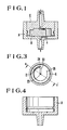
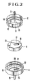
- a flow rate regulator in accordance with the present invention is substantially constituted by a first cylindrical member A, a disc-shaped member B and a second cylindrical member C.
- the first cylindrical member A has a bottom portion 19 which is formed with a peripherally extending groove 21 of which cross-section exhibits a V-shaped contour.
- the groove 21 has a width and a depth both of which is gradually increased from a start point 25 to an end point 24.
- the groove 21 has a cross-sectional area which is increased gradually.
- the groove 21 is communicated with a radially extending groove 23 on the bottom portion 19 via the end point 24 having the largest cross-sectional area.
- the groove 23 has the same cross-sectional area as that of the groove 21 or a cross-sectional area more than that of the same. As is apparent from the drawing, the groove 23 extends toward the center of the bottom portion 19 until it is communicated with a through hole 20 in the first cylindrical member A.
- the disc-shaped member B has also a through hole 18 formed therein which is communicated with the groove 21 when the disc-shaped member B is assembled in the first cylindrical member A.
- liquid medicine or blood to be transfused hereinafter referred to simply as liquid
- the start point 25 of the groove 21 which is communicated with the through hole 18 in the disc-shaped member B defines the smallest cross-sectional area along the whole flow passage of the liquid so that the smallest flow rate is determined by the start point 25 of the groove 21.
- the disc-shaped member B is formed with a radially extending groove 17 on the upper surface thereof which extends from the through hole 18 to the center of the second cylindrical member B.
- the disc-shaped member B is formed with a cutout 16 on the upper surface.
- the second cylindrical member C has a through hole 15 formed at the center of a bottom portion 13, and a protrusion 12 is provided inside of the second cylindrical member C at a position corresponding to the cutout 16 on the disc-shaped member B.
- the protrusion 12 on the second cylindrical member C and the cutout 16 on the disc-shaped member B are provided to assure that member B and the member C are not rotated relative to each other. It should of course be understood that the present invention should not be limited only to the foregoing provision for the purpose of inhibiting the members B and C from being rotated relative to each other. Other relative rotation inhibiting means may be employed for the same purpose, if it is proven that it functions satisfactorily.
- the member A is provided with an annular protrusion 22 round the inner wall surface and the member C is formed with an annular groove 14 round the outer wall surface so that both the members A and C are rotatably assembled together by fitting the protrusion 22 in the groove 14.
- a positional relationship of the annular protrusion 22 relative to the annular groove 14 should be so set that the member B is brought in close contact with the bottom surface of the member A in the presence of the member C.
- elastomeric material such as plasticizable polyvinyl chloride, polyurethane, silicone rubber or the like is employed for the member B rather than hard plastic material.
- a liquid is introduced into the interior of the member C via an inlet port 11 and the through hole 15. It flows through the groove 17 and the through hole 18 in the member C and further flows through the grooves 21 and 23 on the member A until it is discharged from an outlet port 26. Regulating of a flow rate is achieved by rotating the member C relative to the member A and vice versa. As the member C is rotated along with the member B, a positional relationship of the through hole 18 in the member B relative to the groove 21 on the bottom portion of the member A is varied so that the cross-sectional area of the groove 21 is varied correspondingly. This makes it possible to regulate the flow rate to a required value. If both the members A and C are calibrated in a suitable manner, calibrations prepared on them can be used as a measure for setting a flow rate as required.
- both the grooves 17 and 23 are formed in order to assure that the inlet port 11 and the outlet port 26 are located along the axis line of the flow rate regulator of the present invention. If the inlet port 11 and the through hole 15 in the member C may be located in alignment with the through hole 18 in the member B and the outlet port 26 and the through hole 20 in the member A may be located in alignment with the start point 25 of the groove 23, both the grooves 17 and 23 will not be required. It should be noted that a manner of fitting the member A onto the member C should not be limited only to the aforementioned arrangement. Other type of arrangement may be employed, if it is proven that it is acceptable.
- a liquid medicine transfusion unit or blood transfusion unit is constituted by a bottle needle, a drip chamber, a vein needle and a tube connected to the latter.
- the flow rate regulator of the present invention is incorporated in the upper part or the lower part of the drip chamber.
- the regulator may be united with the drip chamber.
- the regulator may be disposed midway of a liquid medicine or blood transfusion line. Since a flow rate is varied when the flow rate regulating part of the regulator is clogged with some foreign material, it is preferable that a filter is disposed upstream of the regulator.
- a filter is often incorporated in the liquid medicine or blood transfusion unit. Provision of the filter in that way makes it possible to reduce the number of components for the transfusion unit. It is preferable that pores in the filter have a diameter in the range of 0.1 to 30 microns.
- the members A and C were molded of ABS resin and the member was molded of plasticizable polyvinyl chloride. These members were assembled together in the above-mentioned manner to provide a flow rate regulator.
- the regulator was incorporated in a liquid medicine transfusion unit. How far a flow rate was varied as time elapsed was observed while water having a temperature varied within the range of 5 °C to 40 °C was caused to flow through the transfusion unit under a differential height of 65 cm.
- similar tests were conducted using a roller clamp which was widely used as a roller clamp having a reduced amount of fluctuation in flow rate.
- the roller clamp used for the tests included a roller which had a V-shaped groove formed thereon.
- the flow rate regulator of the present invention exhibits few fluctuation in flow rate irrespective of variation of the environmental temperature.
- the conventional clamp roller exhibits a large amount of fluctuation in flow rate in response to variation of the environmental temperature. It will be readily understood that a flow rate can be maintained in a very stable state by disposing a filter upstream of the flow rate regulator.
Landscapes
- Health & Medical Sciences (AREA)
- Physics & Mathematics (AREA)
- Engineering & Computer Science (AREA)
- Biomedical Technology (AREA)
- Hematology (AREA)
- Automation & Control Theory (AREA)
- Vascular Medicine (AREA)
- Anesthesiology (AREA)
- General Physics & Mathematics (AREA)
- Heart & Thoracic Surgery (AREA)
- Fluid Mechanics (AREA)
- Life Sciences & Earth Sciences (AREA)
- Animal Behavior & Ethology (AREA)
- General Health & Medical Sciences (AREA)
- Public Health (AREA)
- Veterinary Medicine (AREA)
- Infusion, Injection, And Reservoir Apparatuses (AREA)
Priority Applications (3)
| Application Number | Priority Date | Filing Date | Title |
|---|---|---|---|
| EP89106052A EP0390949B1 (de) | 1989-04-06 | 1989-04-06 | Durchflussregler für Medizinlösungen oder für Bluttransfusionsgeräte |
| DE89106052T DE68907402T2 (de) | 1989-04-06 | 1989-04-06 | Durchflussregler für Medizinlösungen oder für Bluttransfusionsgeräte. |
| US07/335,408 US5045068A (en) | 1989-04-06 | 1989-04-10 | Flow rate regulator for liquid medicine or blood transfusion unit |
Applications Claiming Priority (1)
| Application Number | Priority Date | Filing Date | Title |
|---|---|---|---|
| EP89106052A EP0390949B1 (de) | 1989-04-06 | 1989-04-06 | Durchflussregler für Medizinlösungen oder für Bluttransfusionsgeräte |
Publications (2)
| Publication Number | Publication Date |
|---|---|
| EP0390949A1 true EP0390949A1 (de) | 1990-10-10 |
| EP0390949B1 EP0390949B1 (de) | 1993-06-30 |
Family
ID=8201185
Family Applications (1)
| Application Number | Title | Priority Date | Filing Date |
|---|---|---|---|
| EP89106052A Expired - Lifetime EP0390949B1 (de) | 1989-04-06 | 1989-04-06 | Durchflussregler für Medizinlösungen oder für Bluttransfusionsgeräte |
Country Status (3)
| Country | Link |
|---|---|
| US (1) | US5045068A (de) |
| EP (1) | EP0390949B1 (de) |
| DE (1) | DE68907402T2 (de) |
Cited By (4)
| Publication number | Priority date | Publication date | Assignee | Title |
|---|---|---|---|---|
| ITVI20100205A1 (it) * | 2010-07-23 | 2012-01-24 | Phoenix R & D S R L | Regolatore di flusso per linee di infusione di fluidi medicali |
| CN102380143A (zh) * | 2011-08-23 | 2012-03-21 | 余运贤 | 输液器液流观察器 |
| CN103948988A (zh) * | 2014-05-05 | 2014-07-30 | 山东建筑大学 | 一种带拨盘流量调节装置的静脉输液器 |
| EP3254987A1 (de) * | 2015-09-30 | 2017-12-13 | Shenzhen First Union Technology Co., Ltd. | Nachfüllbare vorrichtung |
Families Citing this family (22)
| Publication number | Priority date | Publication date | Assignee | Title |
|---|---|---|---|---|
| US5178186A (en) * | 1991-03-14 | 1993-01-12 | Levasseur Joseph E | Axial two-way valve-stopcock combination |
| US5755683A (en) * | 1995-06-07 | 1998-05-26 | Deka Products Limited Partnership | Stopcock valve |
| US6709417B1 (en) | 1995-06-07 | 2004-03-23 | Deka Products Limited Partnership | Valve for intravenous-line flow-control system |
| US6165154A (en) * | 1995-06-07 | 2000-12-26 | Deka Products Limited Partnership | Cassette for intravenous-line flow-control system |
| US6210361B1 (en) | 1997-08-22 | 2001-04-03 | Deka Products Limited Partnership | System for delivering intravenous drugs |
| US6364857B1 (en) | 1995-06-07 | 2002-04-02 | Deka Products Limited Partnership | Cassette for intravenous-line flow-control system |
| US5947954A (en) * | 1997-11-19 | 1999-09-07 | Creative Plastic Technology, Llc | Needle-less luer actuated medical connector |
| CA2374846C (en) * | 1999-06-01 | 2008-05-27 | Jean M. Bonaldo | Needle-less luer activated medical connector |
| US6364869B1 (en) * | 2000-06-07 | 2002-04-02 | Creative Plastics Technology, Llc | Medical connector with swabbable stopper |
| US20020166989A1 (en) * | 2001-05-08 | 2002-11-14 | Peterson Michael J. | Valve assembly |
| US7118560B2 (en) * | 2003-02-28 | 2006-10-10 | Creative Plastic Technology, Llc | Needleless Luer activated medical connector |
| US8158102B2 (en) | 2003-10-30 | 2012-04-17 | Deka Products Limited Partnership | System, device, and method for mixing a substance with a liquid |
| US7354190B2 (en) | 2003-10-30 | 2008-04-08 | Deka Products Limited Partnership | Two-stage mixing system, apparatus, and method |
| US7662139B2 (en) * | 2003-10-30 | 2010-02-16 | Deka Products Limited Partnership | Pump cassette with spiking assembly |
| US7624473B2 (en) | 2004-01-07 | 2009-12-01 | The Hoover Company | Adjustable flow rate valve for a cleaning apparatus |
| US8062269B2 (en) * | 2006-06-09 | 2011-11-22 | Baxter International Inc. | Fail safe dual chamber peritoneal dialysis/infusion system |
| EP2345355B1 (de) * | 2006-12-06 | 2013-04-24 | RHEAVENDORS SERVICES S.p.A. | Gerät zur Ausgabe von Getränken und Methode |
| DE102011052196B4 (de) * | 2011-07-27 | 2017-06-08 | MAQUET GmbH | Vorrichtung zum Absaugen von Flüssigkeiten und/oder Partikeln aus Körperöffnungen |
| EP4026893A3 (de) | 2015-10-09 | 2022-09-28 | DEKA Products Limited Partnership | Fluidpumpen- und bioreaktorsystem |
| US9841132B2 (en) * | 2016-05-10 | 2017-12-12 | Mei Thung Co., Ltd. | Quick connector |
| US11299705B2 (en) | 2016-11-07 | 2022-04-12 | Deka Products Limited Partnership | System and method for creating tissue |
| CN112691255B (zh) * | 2020-12-28 | 2022-08-26 | 青岛大学附属医院 | 一种血液科室用往复式定速输血调节装置 |
Citations (4)
| Publication number | Priority date | Publication date | Assignee | Title |
|---|---|---|---|---|
| US3323774A (en) * | 1963-11-26 | 1967-06-06 | Resiflex Lab | Composite closure-drip chamber-valve means unit for administration of liquids |
| FR2153360A1 (de) * | 1971-09-23 | 1973-05-04 | Siemens Ag | |
| WO1984004460A1 (en) * | 1983-05-16 | 1984-11-22 | Health Care Concepts Inc | I.v. flow regulator |
| DE3538890A1 (de) * | 1984-11-02 | 1986-09-11 | Codan Medizinische Geräte GmbH & Co KG, 2432 Lensahn | Vorrichtung zur regulierung des durchflusses bei der schwerkraft-infusion und -transfusion |
Family Cites Families (6)
| Publication number | Priority date | Publication date | Assignee | Title |
|---|---|---|---|---|
| IL65024A (en) * | 1976-10-27 | 1989-07-31 | Bron Dan | Intravenous infusion set |
| US4300250A (en) * | 1980-01-25 | 1981-11-17 | Taylor Merritt I | Beehives |
| DE8324276U1 (de) * | 1983-08-24 | 1984-02-02 | Festo KG, 7300 Esslingen | Drosselvorrichtung |
| US4802506A (en) * | 1984-07-13 | 1989-02-07 | Aslanian Jerry L | Flow control device for administration of intravenous fluids |
| DE8432064U1 (de) * | 1984-11-02 | 1985-05-02 | Codan Medizinische Geräte GmbH & Co KG, 2432 Lensahn | Vorrichtung zur regulierung des durchflusses bei der schwerkraft-infusion und -transfusion |
| US4738665A (en) * | 1985-09-27 | 1988-04-19 | Hall Hill Co. | Method and apparatus for controlling flow rate of fluid |
-
1989
- 1989-04-06 EP EP89106052A patent/EP0390949B1/de not_active Expired - Lifetime
- 1989-04-06 DE DE89106052T patent/DE68907402T2/de not_active Expired - Fee Related
- 1989-04-10 US US07/335,408 patent/US5045068A/en not_active Expired - Fee Related
Patent Citations (4)
| Publication number | Priority date | Publication date | Assignee | Title |
|---|---|---|---|---|
| US3323774A (en) * | 1963-11-26 | 1967-06-06 | Resiflex Lab | Composite closure-drip chamber-valve means unit for administration of liquids |
| FR2153360A1 (de) * | 1971-09-23 | 1973-05-04 | Siemens Ag | |
| WO1984004460A1 (en) * | 1983-05-16 | 1984-11-22 | Health Care Concepts Inc | I.v. flow regulator |
| DE3538890A1 (de) * | 1984-11-02 | 1986-09-11 | Codan Medizinische Geräte GmbH & Co KG, 2432 Lensahn | Vorrichtung zur regulierung des durchflusses bei der schwerkraft-infusion und -transfusion |
Cited By (4)
| Publication number | Priority date | Publication date | Assignee | Title |
|---|---|---|---|---|
| ITVI20100205A1 (it) * | 2010-07-23 | 2012-01-24 | Phoenix R & D S R L | Regolatore di flusso per linee di infusione di fluidi medicali |
| CN102380143A (zh) * | 2011-08-23 | 2012-03-21 | 余运贤 | 输液器液流观察器 |
| CN103948988A (zh) * | 2014-05-05 | 2014-07-30 | 山东建筑大学 | 一种带拨盘流量调节装置的静脉输液器 |
| EP3254987A1 (de) * | 2015-09-30 | 2017-12-13 | Shenzhen First Union Technology Co., Ltd. | Nachfüllbare vorrichtung |
Also Published As
| Publication number | Publication date |
|---|---|
| DE68907402T2 (de) | 1994-02-03 |
| DE68907402D1 (de) | 1993-08-05 |
| US5045068A (en) | 1991-09-03 |
| EP0390949B1 (de) | 1993-06-30 |
Similar Documents
| Publication | Publication Date | Title |
|---|---|---|
| EP0390949B1 (de) | Durchflussregler für Medizinlösungen oder für Bluttransfusionsgeräte | |
| US4142523A (en) | Flow control device for the intravenous administration of liquids | |
| CA1210292A (en) | Solution administration set | |
| US4676772A (en) | Adjustable implantable valve having non-invasive position indicator | |
| US5009251A (en) | Fluid flow control | |
| EP0957951B1 (de) | Tropfkammer zum entgasen von flüssigkeiten | |
| EP0142558B1 (de) | Intravenöser flussregler | |
| US4822344A (en) | Apparatus for controlling fluid flow rate | |
| EP1480696B1 (de) | Druck ausgleichender iv-flussregulator | |
| CA1056683A (en) | Hydrophobic valve | |
| US4014797A (en) | Intravenous injection apparatus and needle adapter with filter and method of making same | |
| US4269222A (en) | Constant flow device | |
| JPH0359712B2 (de) | ||
| CA1256083A (en) | Flow control device for administration of iv fluids | |
| US4925451A (en) | I.V. flow control device | |
| CA1058036A (en) | Volume limiting chamber with air bypass for intravenous set | |
| US4917687A (en) | Apparatus for controlling fluid flow rate | |
| US5101854A (en) | Low-output flow regulator | |
| EP0385424A2 (de) | Einstechdorn für ein Infusionssystem | |
| CA1092467A (en) | Flow control device for example for the intravenous administration of liquids | |
| US3970084A (en) | Intravenous injection apparatus and needle adapter with filter and method of making same | |
| EP1135179B1 (de) | Durchflussregler | |
| CA1308333C (en) | Flow rate regulator for liquid medicine or blood transfusion unit | |
| CN1024895C (zh) | 用于液体药剂输入设备或输血设备的流量调节器 | |
| JP2744799B2 (ja) | 静脈流体投与用流れ制御装置 |
Legal Events
| Date | Code | Title | Description |
|---|---|---|---|
| PUAI | Public reference made under article 153(3) epc to a published international application that has entered the european phase |
Free format text: ORIGINAL CODE: 0009012 |
|
| AK | Designated contracting states |
Kind code of ref document: A1 Designated state(s): DE FR GB IT SE |
|
| 17P | Request for examination filed |
Effective date: 19910102 |
|
| 17Q | First examination report despatched |
Effective date: 19920406 |
|
| ITF | It: translation for a ep patent filed |
Owner name: ING. ZINI MARANESI & C. S.R.L. |
|
| GRAA | (expected) grant |
Free format text: ORIGINAL CODE: 0009210 |
|
| AK | Designated contracting states |
Kind code of ref document: B1 Designated state(s): DE FR GB IT SE |
|
| REF | Corresponds to: |
Ref document number: 68907402 Country of ref document: DE Date of ref document: 19930805 |
|
| ET | Fr: translation filed | ||
| PLBE | No opposition filed within time limit |
Free format text: ORIGINAL CODE: 0009261 |
|
| STAA | Information on the status of an ep patent application or granted ep patent |
Free format text: STATUS: NO OPPOSITION FILED WITHIN TIME LIMIT |
|
| 26N | No opposition filed | ||
| ITPR | It: changes in ownership of a european patent |
Owner name: CAMBIO RAGIONE SOCIA;JMS CO. LTD |
|
| EAL | Se: european patent in force in sweden |
Ref document number: 89106052.7 |
|
| REG | Reference to a national code |
Ref country code: FR Ref legal event code: CD |
|
| PGFP | Annual fee paid to national office [announced via postgrant information from national office to epo] |
Ref country code: GB Payment date: 19970402 Year of fee payment: 9 |
|
| PGFP | Annual fee paid to national office [announced via postgrant information from national office to epo] |
Ref country code: FR Payment date: 19970409 Year of fee payment: 9 |
|
| PGFP | Annual fee paid to national office [announced via postgrant information from national office to epo] |
Ref country code: SE Payment date: 19970418 Year of fee payment: 9 |
|
| PGFP | Annual fee paid to national office [announced via postgrant information from national office to epo] |
Ref country code: DE Payment date: 19970429 Year of fee payment: 9 |
|
| PG25 | Lapsed in a contracting state [announced via postgrant information from national office to epo] |
Ref country code: GB Free format text: LAPSE BECAUSE OF NON-PAYMENT OF DUE FEES Effective date: 19980406 |
|
| PG25 | Lapsed in a contracting state [announced via postgrant information from national office to epo] |
Ref country code: SE Free format text: LAPSE BECAUSE OF NON-PAYMENT OF DUE FEES Effective date: 19980407 |
|
| PG25 | Lapsed in a contracting state [announced via postgrant information from national office to epo] |
Ref country code: FR Free format text: THE PATENT HAS BEEN ANNULLED BY A DECISION OF A NATIONAL AUTHORITY Effective date: 19980430 |
|
| GBPC | Gb: european patent ceased through non-payment of renewal fee |
Effective date: 19980406 |
|
| EUG | Se: european patent has lapsed |
Ref document number: 89106052.7 |
|
| PG25 | Lapsed in a contracting state [announced via postgrant information from national office to epo] |
Ref country code: DE Free format text: LAPSE BECAUSE OF NON-PAYMENT OF DUE FEES Effective date: 19990202 |
|
| REG | Reference to a national code |
Ref country code: FR Ref legal event code: ST |
|
| PG25 | Lapsed in a contracting state [announced via postgrant information from national office to epo] |
Ref country code: IT Free format text: LAPSE BECAUSE OF NON-PAYMENT OF DUE FEES;WARNING: LAPSES OF ITALIAN PATENTS WITH EFFECTIVE DATE BEFORE 2007 MAY HAVE OCCURRED AT ANY TIME BEFORE 2007. THE CORRECT EFFECTIVE DATE MAY BE DIFFERENT FROM THE ONE RECORDED. Effective date: 20050406 |