EP0389931A1 - Brake control apparatus for bicycle - Google Patents
Brake control apparatus for bicycle Download PDFInfo
- Publication number
- EP0389931A1 EP0389931A1 EP90105257A EP90105257A EP0389931A1 EP 0389931 A1 EP0389931 A1 EP 0389931A1 EP 90105257 A EP90105257 A EP 90105257A EP 90105257 A EP90105257 A EP 90105257A EP 0389931 A1 EP0389931 A1 EP 0389931A1
- Authority
- EP
- European Patent Office
- Prior art keywords
- lever
- cable
- movement
- control lever
- cam face
- Prior art date
- Legal status (The legal status is an assumption and is not a legal conclusion. Google has not performed a legal analysis and makes no representation as to the accuracy of the status listed.)
- Granted
Links
Images


Classifications
-
- B—PERFORMING OPERATIONS; TRANSPORTING
- B62—LAND VEHICLES FOR TRAVELLING OTHERWISE THAN ON RAILS
- B62L—BRAKES SPECIALLY ADAPTED FOR CYCLES
- B62L3/00—Brake-actuating mechanisms; Arrangements thereof
- B62L3/02—Brake-actuating mechanisms; Arrangements thereof for control by a hand lever
-
- B—PERFORMING OPERATIONS; TRANSPORTING
- B62—LAND VEHICLES FOR TRAVELLING OTHERWISE THAN ON RAILS
- B62K—CYCLES; CYCLE FRAMES; CYCLE STEERING DEVICES; RIDER-OPERATED TERMINAL CONTROLS SPECIALLY ADAPTED FOR CYCLES; CYCLE AXLE SUSPENSIONS; CYCLE SIDE-CARS, FORECARS, OR THE LIKE
- B62K23/00—Rider-operated controls specially adapted for cycles, i.e. means for initiating control operations, e.g. levers, grips
- B62K23/02—Rider-operated controls specially adapted for cycles, i.e. means for initiating control operations, e.g. levers, grips hand actuated
- B62K23/06—Levers
Definitions
- the present invention relates to a brake control apparatus for a bicycle, and more particularly to a brake control apparatus having a control lever and a cable operatively connected to the lever to be pulled thereby.
- a cable movement ratio is defined here as a ratio obtained by dividing an amount of movement of the cable caused by a unit amount of operation of the control lever from a certain position by said unit operation amount of the control lever.
- a force transmission ratio is defined here as a ratio which varies in inverse proportion to the above-defined cable movement ratio. That is to say, supposing an input of the unit operation amount of the control lever results in a certain amount of output force from the cable in its longitudinal direction; then, the force transmission ratio is obtained by dividing this output force of the cable by the unit operation amount of the control lever.
- control lever is pivotably attached to a bracket and the cable is attached through a hole defined at a base of the control lever. Accordingly, the connecting position between the cable and the lever remains fixed relative to the pivot of the lever, regardless of an operational position of the lever.
- the connecting portion of the cable pivots about the pivot of the control lever. Then, as the operation amount of the control lever varies, the value of the above-defined cable movement ratio varies to approximate a sine curve. That is, in the conventional apparatus, the cable movement ratio is not positively differentiated according to various operational positions of the control lever. Further, the conventional apparatus has a small cable movement ratio in the initial inoperative (i.e. play) stroke of the control lever before the actuated lever brings the brake shoes, via the cable, to come into contact with the wheel rim for braking the same. This is to say that much of the limited lever stroke is used to cover the distance of the inoperative stroke. Consequently, the operative stroke of the lever, i.e. the lever stroke after the contact between the shoes and the rim is significantly limited, whereby the brake control apparatus provides only insufficient braking force.
- the primary object of the present invention is to provide a brake control apparatus for a bicycle which apparatus can provide sufficient braking force by effectively reducing the inoperative stroke of the control lever.
- a brake control apparatus for a bicycle comprises: a control lever operable to pull a cable connected thereto; and a cable movement ratio varying mechanism operable in response to an operation of the control lever for varying a cable movement ratio obtained by dividing an amount of movement of the cable caused by a unit amount of operation of the control lever from a position thereof by the unit operation amount of the control lever; the varying mechanism rendering, in vicinity of an end of an inoperative stroke of the control lever between a lever movement start position and a lever movement finish position, a differential coefficient of a function of the cable movement ratio smaller on the side of the lever movement start position than than on the side of the lever movement finish position across the inoperative stroke end, the function varying according to an operational amount of the control lever.
- the cable movement ratio varying mechanism operable in response to an operation of the control lever for varying the cable movement ratio, it has become possible to freely or variably set the movement amount of the cable according to an operational position of the control lever.
- the cable movement ratio varying mechanism renders a differential coefficient of a function of the cable movement ratio smaller on the side of the lever movement start position than than on the opposite side of the lever movement finish position across the inoperative stroke end.
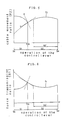
- Fig. 5 graphically shows a curve of a function f2 of the above-described cable movement ratio R2 relative to variation of the operation amount of the control lever, with the lever operation amount and the movement ratio being represented by the X axis and Y axis, respectively.
- a first tangent X is drawn to the function curve f2 on the side of the lever movement start point Ss i.e. the origin of this graph; whereas a second tangent Y is drawn to the function curve f2 on the opposite side of the lever movement finish point Se past the inflection point of the inoperative stroke end Sle.
- the tangent has a clockwise slope relative to the the tangent Y. This is the effect realized by the above-described cable movement ratio varying mechanism.
- the function of the lever movement ratio of the conventional apparatus approximates a sine curve, which means the first tangent has a counterclockwise slope relative to the second tangent. Consequently, the inoperative stroke occupies a greater portion of the entire stroke of the control lever, leaving only considerably limited portion for its operative stroke, whereby the apparatus can achieve inferior braking performance.
- control lever is pivotable, and the cable movement ratio varying mechanism varies the cable movement ratio by changing a ratio between an arm length of moment acting on a grip portion of the lever with a pivotal operation of the same and an arm length of moment acting on the cable.
- variable cable movement ratio can be obtained only by changing the ratio between the two arm lengths. Further, a desired amount of change in the ratio can be realized merely by changing the length of only one of the two arms relative to the other which length is fixed. Accordingly, the construction with these features allows greater freedom in the designing and can be constructed very simple.
- control lever is pivotably attached to a bracket via a lever shaft
- control apparatus further comprising a cable connecting portion for operatively connecting the cable with the control lever, the mechanism for varying the arm length ratio including a cam device for moving the cable connecting portion along a moving direction of the cable so as to move the cable connecting portion closer to and away from the lever shaft.
- control lever is pivotably attached to a bracket via a lever shaft
- control apparatus further comprises a cable connecting portion for operatively connecting the cable with the control lever.
- the mechanism for varying the arm length ratio includes a cam device for moving the cable connecting portion along a moving direction of the cable so as to move the cable connecting portion closer to and away from the lever shaft.
- a brake control apparatus for a bicyle is to be attached to a curved portion of a drop handle H of the bicycle body.
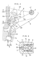
- the apparatus includes, a bracket 1 having a pair of opposing side faces 1a and 1b and a lever intserting portion between the side faces 1a, 1b, so that a base 31 of a control lever 3 is pivotably attached through the lever inserting portion via a lever shaft 4.
- the apparatus is fixed through its band member 2 to the curved handle portion.
- the bracket 1 is formed as an angular hollow construction including the above-mentioned side faces 1a and 1b and a front face 1c and a rear face 1d connecting between the side faces 1a, 1b.
- the lever inserting portion 11 is formed as an opening defined at an upper portion of the rear face 1d between the opposing side faces 1a, 1b.
- an intermediate wall 12 which supports a fastner bolt 2a engageable with the band member 2. Further, this intermediate wall 12 forms an inserting hole 13 for an inner cable 51 of a control cable 5 and an outer receiver 14 for receiving an outer tube 52 of the cable 5.
- the control lever 3 includes the base portion 31 having a letter 'U' shaped cross section and inserted through the lever inserting portion 11 of the bracket 1 and a bar-shaped control portion 32 extending outwardly from an end of the base portion 31.
- the base portion 31 defines a shaft hole for receiving the lever shaft 4 therethrough and supports, at a front end thereof, a cable retainer 7 for retaining a nipple 53 fixed to a distal end of the inner cable 51.
- an entire operational stroke of the control lever 3 is defined by a lever movement start point Ss (i.e. the home position of the lever) predetermined by contact with the bracket 1 and a lever movement finish point Se predetermined by a withdrawable amount of the inner cable 51.
- a cam device 6 including the cable retainer 7 acting as a cable connecting portion for operatively connecting the inner cable 51 with the control lever 3, a guide face 33 formed on the control lever 3 and a cam face 15 attached to the bracket 1.
- the cam face 15 is formed as an element made of synthtic resin material and separately from the bracket 1, so that the cam face 15 is detachable from the bracket 1.
- the cam face 15 includes an elastically deformable stopper element 18 while the bracket 1 includes an engaging portion 19 engageable with the stopper element 18 through elastic deformation of the latter.
- the guide face 33 is formed as a recessed face extending from a front end edge of the base portion 31 of the control lever 3 to a pivot axis 41 of the lever shaft 4.
- the cable retainer 7 is a cylindrical structure having, a support hole extending radially at a longitudinal intermediate portion of the structure for receiving the nipple 53 therethrough.
- retainer 7 has its arcuate outer periphery placed in contact with the cam face 15 and has its reduced diameter portions movably supported by the guide face 33 through a pair of bushes 71. Accordingly, this cable retainer 7 has its moving path defined in its relation with the cam face 15.
- moment acting on the cable retainer 7 is obtained as a product of an output force P2 acting along the longitudinal direction of the inner cable 51 associated with the input force P1 of the control lever 3 multipled by a length L2 of an output arm defined by a perpendicular line drawn from the lever shaft 4 to an extension of the output force P2.
- (P1) x (L1) (P2) x (L2) Eq. (a)
- (P2) ((P1) x (L1)) / (L2) Eq. (b)
- the cable movement ration R2 varies in inverse proportion to the output force P2 of the inner cable 51.
- the force transmission ratio RI varies in inverse proportion to the cable movement ratio R2.
- the function curve f1 represents variation of the force transmission ratio R1 with respect to variation in the operation amount of the control lever 3 which is represented by the X axis.
- the function curve f2 represents variation of the cable movement ratio R2 with respect to variation in the operation amount of the control lever 3 which is represented by the X axis.
- the entire stroke of the control lever 3 consists of two continous ranges, between the lever movement start point Ss and the lever movement finish point Se, that is an inoperative (i.e. play) stroke S1 before and until a brake shoe cames into contact with a rim of a bicycle wheel and an operative stroke S2 where the brake shoe actually brakes the rotating rim after the above contact.
- the cam face 15 includes first and second cam faces 16 and 17 having different curves, so as to vary the cable movement ratio R2 in a manner described next.
- the first cam face 16 corresponding to the inoperative stroke S1 is formed as a curve extending from a point of the cam face 15 most distant from the pivot axis 41 of the lever shaft 4 to gradually approach this axis 41, so as to move a center 72 of the cable retainer 7 gradually closer to the pivot axis 41 as the lever pulling operation proceeds. Accordingly, during the inoperative stroke S1, the cable movement ratio R2 is relatively large, and therefore a small amount of lever pulling operation can quickly bring the brake shoe and the rim into contact with each other for subsequent braking operation, even if the shoe and the rim are designed with a relatively large clearance therebetween.
- the second cam face 17 is formed continously from a terminal end 16e of the above-described first cam face 16, so that the function curve f2 of the cable movement ratio R2 is formed continous through the entire stroke of the control lever 3.
- a differential coefficient of the function curve f2 of the cable movement ratio R2 which varies with the operational amount of the control lever 3 is smaller on the side of the lever movement start point Ss than on the opposite side of the lever movement finish point Se across the inoperative stroke end Sle.
- the above-mentioned “vicinity" of the end Sle of the inoperative stroke S1 is understood as including the point of the end Sle per se. Also, this end Sle of the inoperative stroke S1 is predetermined by design of the entire brake system such as of the brake shoe, and the end Sle may differ from an end of an actual inoperative range depending on the design.
- alternate long and two short dashed lines represent function curves of the cable movement ratio R2 and the force transmission ratio R1 obtained by the conventional brake control apparatus.
- a mark S2′ denotes an operative stroke of this conventional apparatus.
- the operative stroke S2 of the apparatus of the present invention is greater than the stroke S2′ of the conventional apparatus, which means that the former can achieve better braking performance than the latter.
- a brake control apparatus relating to this second embodiment is designed for use in the so-called all-terrain bicycle (commonly referred to as an ATB).
- ATB all-terrain bicycle
- Numeral 35 denotes a takeup member pivotable about a lever shaft 4′ relative to a bracket 1′ with a pivotal operation of a control lever 3′ so as to take up the inner cable 51.
- This takeup member 35 includes, at a position on its outer periphery portion 36 thereof, a retainer portion 37 for retaining the distal end of the nipple 53, so that the takeup member 35 pulls and takes up the inner cable 51 about the outer periphery portion 36 with a pulling operation of the control lever 3′.
- the outer periphery portion 36 is so configurated as to have its distance to the lever shaft 4′ vary according to the operational position of the control lever 3′, thus positively varying the output arm length L2 of the moment acting on the inner cable and consequently the cable movement ratio R2.
- a brake control apparatus of this third embodiment is designed also for use in the ATB type bicycle, as is the case with the apparatus of the above second embodiment.
- the base of the control lever 3′ mounts, on one side thereof, a shaft, on which a cable retainer 38 is pivotably attached.
- the bracket 1′ at a forward position in the pivotal direction of the lever 3′, pivotably mounts a contact roller 39 which comes into contact with the inner cable with a lever pulling operation. In operation, when the control lever 3′ is pulled, first, the inner cable 51 moves closer to the lever shaft 4′, thus gradually reducing the output arm length L2 of the cable.
- the cam face 15 includes the first cam face 16 and the second cam face 17. Of these faces, the second cam face 17 is eliminated in this fourth embodiment.
- the guide face 33 is so formed that the guide face 33 and a line Z along the cable pulling direction form an angle ⁇ not greater than 90 degrees when the cable retainer 7 has passed the terminal end 16e′.
- the function f2 of the cable movement ratio R2 for the operative stroke S2 can be freely set.
- the function f2 can have a gradually increasing value to the lever movement finish point Se.
- the value of the function f2 can gradually decrease in the same direction.
- the value of the cable movement ratio R2 it is also conceivable for the value of the cable movement ratio R2 to drop sharply in the vicinity of the inoperative stroke end Sle while the same remains constant through the operative stroke S2.
- the function f2 of the cable movement ratio R2 can be discontinued in the vicinity of the inoperative range end Sle.
- the force transmission ratio R1 is changed by varying the output arm length L2.
- the ration R1 can be changed by varying the input arm length L1.
- it is conceivable to construct a quadrople link mechanism by pivotably attaching the control lever 3 to the bracket 1 by means of a pair of link elements. Then, by appropriately setting pivot-to-pivot distances of this mechanism, the input arm length L1 can be changed for varying the force transmission ratio R1 to a desired value.
- the cam face 15 attached to the front face 1c of the bracket 1 can be attached to either of the side faces 1a, 1b. In this case, the opposite ends of the cable retainer 7 will be outwardly extended so as to come into contact with the cam face 15 directly or through bushes or the like.
- the specific configuration of the cam face 15 is not limited to the one described in the first embodiment but can be designed differently depending on the convenience.
- the cable retainer 7 supported to the control lever 3 remain disconnected from the cable 5. Yet, the retainer 7 can be connected with the cable 5 in some occasions. That is, the specific construction of this cable retainer 7 is not essential for the present invention.
- the cam face 15 is formed of synthetic resin material and separately from the bracket 1 so as to be freely detachable from the bracket 1. Instead, the cam face 15 can be formed integrally with the bracket 1.
- the in-tube type cable 5 having the outer tube 5 can be substituted by the inner cable 51 alone.
Abstract
Description
- The present invention relates to a brake control apparatus for a bicycle, and more particularly to a brake control apparatus having a control lever and a cable operatively connected to the lever to be pulled thereby.
- Before describing the invention in details, it should be helpful to explain and define some concepts which are essential for full understanding of the invention with respect to the prior art.
- First, a cable movement ratio is defined here as a ratio obtained by dividing an amount of movement of the cable caused by a unit amount of operation of the control lever from a certain position by said unit operation amount of the control lever.
- Second, considering the possiblity where the amount of work applied to the control lever equates with the amount of work transmitted to the cable; then, a force transmission ratio is defined here as a ratio which varies in inverse proportion to the above-defined cable movement ratio. That is to say, supposing an input of the unit operation amount of the control lever results in a certain amount of output force from the cable in its longitudinal direction; then, the force transmission ratio is obtained by dividing this output force of the cable by the unit operation amount of the control lever. These cable movement ratio and the force transmission ratio are predetermined by the construction of the brake control apparatus per se and are not directly affected by elastic modulus of the brake shoe and/or of the cable.
- In a conventional bicycle brake control apparatus, such as an apparatus disclosed in a Japanese published utility model No. 57-9193, the control lever is pivotably attached to a bracket and the cable is attached through a hole defined at a base of the control lever. Accordingly, the connecting position between the cable and the lever remains fixed relative to the pivot of the lever, regardless of an operational position of the lever.
- With the above-described conventional apparatus, the connecting portion of the cable pivots about the pivot of the control lever. Then, as the operation amount of the control lever varies, the value of the above-defined cable movement ratio varies to approximate a sine curve. That is, in the conventional apparatus, the cable movement ratio is not positively differentiated according to various operational positions of the control lever. Further, the conventional apparatus has a small cable movement ratio in the initial inoperative (i.e. play) stroke of the control lever before the actuated lever brings the brake shoes, via the cable, to come into contact with the wheel rim for braking the same. This is to say that much of the limited lever stroke is used to cover the distance of the inoperative stroke. Consequently, the operative stroke of the lever, i.e. the lever stroke after the contact between the shoes and the rim is significantly limited, whereby the brake control apparatus provides only insufficient braking force.
- Then, the primary object of the present invention is to provide a brake control apparatus for a bicycle which apparatus can provide sufficient braking force by effectively reducing the inoperative stroke of the control lever.
-
- For accomplishing the above-noted object, a brake control apparatus for a bicycle, according to the invention, comprises: a control lever operable to pull a cable connected thereto; and a cable movement ratio varying mechanism operable in response to an operation of the control lever for varying a cable movement ratio obtained by dividing an amount of movement of the cable caused by a unit amount of operation of the control lever from a position thereof by the unit operation amount of the control lever; the varying mechanism rendering, in vicinity of an end of an inoperative stroke of the control lever between a lever movement start position and a lever movement finish position, a differential coefficient of a function of the cable movement ratio smaller on the side of the lever movement start position than than on the side of the lever movement finish position across the inoperative stroke end, the function varying according to an operational amount of the control lever.
- According to the first characterizing features of the invention, because of the cable movement ratio varying mechanism operable in response to an operation of the control lever for varying the cable movement ratio, it has become possible to freely or variably set the movement amount of the cable according to an operational position of the control lever.
- Further, in vicinity of an end of an inoperative stroke of the control lever between a lever movement start position and a lever movement finish position, the cable movement ratio varying mechanism renders a differential coefficient of a function of the cable movement ratio smaller on the side of the lever movement start position than than on the opposite side of the lever movement finish position across the inoperative stroke end. With this, it has become possible to reduce the inoperative stroke before the brake shoe comes into contact with the rim after the control lever actuation. This will be more particularly described with reference to Fig. 5.
- Fig. 5 graphically shows a curve of a function f2 of the above-described cable movement ratio R2 relative to variation of the operation amount of the control lever, with the lever operation amount and the movement ratio being represented by the X axis and Y axis, respectively.
- In this Fig. 5, across the end Sle of the inoperative stroke, a first tangent X is drawn to the function curve f2 on the side of the lever movement start point Ss i.e. the origin of this graph; whereas a second tangent Y is drawn to the function curve f2 on the opposite side of the lever movement finish point Se past the inflection point of the inoperative stroke end Sle. As shown, the tangent has a clockwise slope relative to the the tangent Y. This is the effect realized by the above-described cable movement ratio varying mechanism.
- On the other hand, the opposite is true with the conventional brake control apparatus. That is, the function of the lever movement ratio of the conventional apparatus approximates a sine curve, which means the first tangent has a counterclockwise slope relative to the second tangent. Consequently, the inoperative stroke occupies a greater portion of the entire stroke of the control lever, leaving only considerably limited portion for its operative stroke, whereby the apparatus can achieve inferior braking performance.
- Further, according to second characterizing features of the invention, the control lever is pivotable, and the cable movement ratio varying mechanism varies the cable movement ratio by changing a ratio between an arm length of moment acting on a grip portion of the lever with a pivotal operation of the same and an arm length of moment acting on the cable.
- With the above second features of the invention, the variable cable movement ratio can be obtained only by changing the ratio between the two arm lengths. Further, a desired amount of change in the ratio can be realized merely by changing the length of only one of the two arms relative to the other which length is fixed. Accordingly, the construction with these features allows greater freedom in the designing and can be constructed very simple.
- Still further, according to third characterizing features of the invention, the control lever is pivotably attached to a bracket via a lever shaft, the control apparatus further comprising a cable connecting portion for operatively connecting the cable with the control lever, the mechanism for varying the arm length ratio including a cam device for moving the cable connecting portion along a moving direction of the cable so as to move the cable connecting portion closer to and away from the lever shaft.
- According to the third features of the invention, the control lever is pivotably attached to a bracket via a lever shaft, and the control apparatus further comprises a cable connecting portion for operatively connecting the cable with the control lever. Further, the mechanism for varying the arm length ratio includes a cam device for moving the cable connecting portion along a moving direction of the cable so as to move the cable connecting portion closer to and away from the lever shaft.
- Further and other objects, features and effects of the invention will become more apparent from the following more detailed description of the embodiments of the invention with reference to the accompanying drawings.
-
- Figs. 1 through 6 illustrate a brake control apparatus for a bicycle, relating to a first embodiment of the invention; in which,
- Fig. 1 is a vertical section of the control apparatus,
- Fig. 2 is an enlarged vertical section showing a cam device of the apparatus,
- Fig. 3 is a cross section showing a bracket of the apparatus,
- Fig. 4 is a schematic side view of the apparatus for illustrating the working principle,
- Fig. 5 is a graph of a cable movement ratio, and
- Fig. 6 is a graph of a force transmission ratio,
- Figs. 7 through 12 illustrate further embodiments of the invention; in which,
- Figs. 7 and 8 are views showing major portions about a lever shaft,
- Fig. 9 is a vertical section of a cam device relating to one of the further embodiments, and
- Figs. 10 through 12 are graphs of the cable movement ratio.
- Preferred embodiments of a brake control apparatus for a bicycle, relating to the present invention, will now be particularly described with reference to the accompanying drawings.
- A first embodiment will be described with reference to Figs. 1 through 6. A brake control apparatus for a bicyle is to be attached to a curved portion of a drop handle H of the bicycle body. The apparatus includes, a
bracket 1 having a pair of opposing side faces 1a and 1b and a lever intserting portion between the side faces 1a, 1b, so that abase 31 of acontrol lever 3 is pivotably attached through the lever inserting portion via alever shaft 4. As assembled, the apparatus is fixed through itsband member 2 to the curved handle portion. - The
bracket 1 is formed as an angular hollow construction including the above-mentioned side faces 1a and 1b and a front face 1c and arear face 1d connecting between theside faces lever inserting portion 11 is formed as an opening defined at an upper portion of therear face 1d between theopposing side faces bracket 1, there is disposed anintermediate wall 12 which supports a fastner bolt 2a engageable with theband member 2. Further, thisintermediate wall 12 forms aninserting hole 13 for aninner cable 51 of acontrol cable 5 and anouter receiver 14 for receiving anouter tube 52 of thecable 5. - The
control lever 3 includes thebase portion 31 having a letter 'U' shaped cross section and inserted through thelever inserting portion 11 of thebracket 1 and a bar-shaped control portion 32 extending outwardly from an end of thebase portion 31. Thebase portion 31 defines a shaft hole for receiving thelever shaft 4 therethrough and supports, at a front end thereof, acable retainer 7 for retaining anipple 53 fixed to a distal end of theinner cable 51. - As shown in Figs. 1 and 2, an entire operational stroke of the
control lever 3 is defined by a lever movement start point Ss (i.e. the home position of the lever) predetermined by contact with thebracket 1 and a lever movement finish point Se predetermined by a withdrawable amount of theinner cable 51. - As shown in Figs. 1 through 3, inside the
bracket 1, there is provided a cam device 6 including thecable retainer 7 acting as a cable connecting portion for operatively connecting theinner cable 51 with thecontrol lever 3, aguide face 33 formed on thecontrol lever 3 and acam face 15 attached to thebracket 1. - The
cam face 15 is formed as an element made of synthtic resin material and separately from thebracket 1, so that thecam face 15 is detachable from thebracket 1. For this detachable attachment between thecam face 15 and thebracket 1, thecam face 15 includes an elastically deformable stopper element 18 while thebracket 1 includes an engaging portion 19 engageable with the stopper element 18 through elastic deformation of the latter. - The guide face 33 is formed as a recessed face extending from a front end edge of the
base portion 31 of thecontrol lever 3 to apivot axis 41 of thelever shaft 4. Further, thecable retainer 7 is a cylindrical structure having, a support hole extending radially at a longitudinal intermediate portion of the structure for receiving thenipple 53 therethrough. Thus constructedretainer 7 has its arcuate outer periphery placed in contact with thecam face 15 and has its reduced diameter portions movably supported by theguide face 33 through a pair ofbushes 71. Accordingly, thiscable retainer 7 has its moving path defined in its relation with thecam face 15. - With the above-described construction, as illustrated in Fig. 4, moment acting on the
control lever 3 with a manual operation of thelever 3 at a certain position thereof is transmitted to thecable retainer 7. This moment acting on the grip portion of thecontrol lever 3 can be obtained as a product of an input force P1 applied to thelever 3 multipled by a length L1 of an input arm defined by a perpendicular line drawn from thepivot shaft 4 to an extension of the line of the input force P1. Although the magnitude and direction of the input force PI varies according with the operation of thecontrol lever 3, the amount of this variation is negligible. Therefore, the input arm length L1 can be considered as substantially constant through the entire stroke of thelever 3, regardless of the operational position of the same. On the other hand, moment acting on thecable retainer 7 is obtained as a product of an output force P2 acting along the longitudinal direction of theinner cable 51 associated with the input force P1 of thecontrol lever 3 multipled by a length L2 of an output arm defined by a perpendicular line drawn from thelever shaft 4 to an extension of the output force P2. Then, since the magnitudes of the moment acting on the grip portion and that acting on thecable retainer 7 are substantially the same, we obtain:
(P1) x (L1) = (P2) x (L2) Eq. (a)
(P2) = ((P1) x (L1)) / (L2) Eq. (b) - That is, it is possible to vary the output force P2 by varying the output arm length (L2).
- Suppose a small movement distance of the
control portion 32 caused by a unit input force PI to thecontrol lever 3 at a certain operational position of thelever 3 is d δ p and a small movement distance of theinner cable 51 caused by the unit input force P1 is d δ q, then, according to the law of conservation of momentun, we have:
(P1) x (d δ p) = (P2) x (d δ q) Eq. (c) - Using the Eq. (b), the Eq. (c) can be rewritten as:
(d δ q) = (d δ p) / (L1) x (L2) Eq. (d) - Then, it is possible vary the minute movement distance d δ q by varying the output arm length L2.
- Eq. (c) can be further rewritten as:
(P1)/ (P2) = (d δ q)/(d δ p) = (R2) Eq.(e)
where, R2 is a cable movement ratio. - Assume the input force P1 of the moment acting on the
control lever 3 is substantially constant, the cable movement ration R2 varies in inverse proportion to the output force P2 of theinner cable 51. - Eq. (e) can be further expressed as:
(R1) = 1 / (R2) Eq.(f)
where, R1 is a force transmission ratio. - Therefore, the force transmission ratio RI varies in inverse proportion to the cable movement ratio R2.
- Next, the configuration of the
cam face 15 will now be described with reference to graphs of Figs. 5 sand 6 showing function curves f1 and f2 of the force transmission ratio R1 and the cable movement ratio R2, respectively. - In Fig. 6, the function curve f1 represents variation of the force transmission ratio R1 with respect to variation in the operation amount of the
control lever 3 which is represented by the X axis. In Fig. 6, the function curve f2 represents variation of the cable movement ratio R2 with respect to variation in the operation amount of thecontrol lever 3 which is represented by the X axis. In these graphs, the entire stroke of thecontrol lever 3 consists of two continous ranges, between the lever movement start point Ss and the lever movement finish point Se, that is an inoperative (i.e. play) stroke S1 before and until a brake shoe cames into contact with a rim of a bicycle wheel and an operative stroke S2 where the brake shoe actually brakes the rotating rim after the above contact. - Then, in this first embodiment, as best shown in Fig. 2, the
cam face 15 includes first and second cam faces 16 and 17 having different curves, so as to vary the cable movement ratio R2 in a manner described next. - The
first cam face 16 corresponding to the inoperative stroke S1 is formed as a curve extending from a point of thecam face 15 most distant from thepivot axis 41 of thelever shaft 4 to gradually approach thisaxis 41, so as to move acenter 72 of thecable retainer 7 gradually closer to thepivot axis 41 as the lever pulling operation proceeds. Accordingly, during the inoperative stroke S1, the cable movement ratio R2 is relatively large, and therefore a small amount of lever pulling operation can quickly bring the brake shoe and the rim into contact with each other for subsequent braking operation, even if the shoe and the rim are designed with a relatively large clearance therebetween. Thesecond cam face 17 is formed continously from aterminal end 16e of the above-describedfirst cam face 16, so that the function curve f2 of the cable movement ratio R2 is formed continous through the entire stroke of thecontrol lever 3. - More particularly, in this first embodiment of the invention using the above-described first and second cam faces 16 and 17, in the vicinity of an end Sle of the inoperative stroke S1 corresponding to the
terminal end 16e of thefirst cam face 16, i.e. in the border area between these first and second cam faces, a differential coefficient of the function curve f2 of the cable movement ratio R2, which varies with the operational amount of thecontrol lever 3, is smaller on the side of the lever movement start point Ss than on the opposite side of the lever movement finish point Se across the inoperative stroke end Sle. This can be fully understood by comparing slopes of a tangent X of the inoperative stroke S1 to the function curve f2 and a further tangent Y of the operative stroke S2 to the function curve f2. The above-mentioned "vicinity" of the end Sle of the inoperative stroke S1 is understood as including the point of the end Sle per se. Also, this end Sle of the inoperative stroke S1 is predetermined by design of the entire brake system such as of the brake shoe, and the end Sle may differ from an end of an actual inoperative range depending on the design. - Referring back to Figs. 5 and 6, alternate long and two short dashed lines represent function curves of the cable movement ratio R2 and the force transmission ratio R1 obtained by the conventional brake control apparatus. Further, a mark S2′ denotes an operative stroke of this conventional apparatus. As compared, the operative stroke S2 of the apparatus of the present invention is greater than the stroke S2′ of the conventional apparatus, which means that the former can achieve better braking performance than the latter.
- A second embodiment of the invention will be described next with reference to Fig. 7.
- A brake control apparatus relating to this second embodiment is designed for use in the so-called all-terrain bicycle (commonly referred to as an ATB). In Fig. 7 showing this apparatus, the same members and elements as those in the first embodiment are denoted by the same reference numerals and marks.
Numeral 35 denotes a takeup member pivotable about alever shaft 4′ relative to abracket 1′ with a pivotal operation of acontrol lever 3′ so as to take up theinner cable 51. Thistakeup member 35 includes, at a position on itsouter periphery portion 36 thereof, aretainer portion 37 for retaining the distal end of thenipple 53, so that thetakeup member 35 pulls and takes up theinner cable 51 about theouter periphery portion 36 with a pulling operation of thecontrol lever 3′. Further, theouter periphery portion 36 is so configurated as to have its distance to thelever shaft 4′ vary according to the operational position of thecontrol lever 3′, thus positively varying the output arm length L2 of the moment acting on the inner cable and consequently the cable movement ratio R2. - A third embodiment will be described next with reference to Fig. 8.
- A brake control apparatus of this third embodiment is designed also for use in the ATB type bicycle, as is the case with the apparatus of the above second embodiment. In this apparatus, the base of the
control lever 3′ mounts, on one side thereof, a shaft, on which acable retainer 38 is pivotably attached. On the other hand, thebracket 1′, at a forward position in the pivotal direction of thelever 3′, pivotably mounts acontact roller 39 which comes into contact with the inner cable with a lever pulling operation. In operation, when thecontrol lever 3′ is pulled, first, theinner cable 51 moves closer to thelever shaft 4′, thus gradually reducing the output arm length L2 of the cable. Then, as thelever 3′ is futher pulled, theinner cable 51 comes into contact with thecontact roller 39, which contact changes the direction of the output force P2 of the moment acting on thecable 5, thus increasing the output arm length L2 again after the contact. In this way, the apparatus of this emboidment can vary the cable movement ratio R2. - A fourth embodiment will be described next with reference to Fig. 9.
- In the first embodiment, the
cam face 15 includes thefirst cam face 16 and thesecond cam face 17. Of these faces, thesecond cam face 17 is eliminated in this fourth embodiment. In this case, in order to prevent thecable retainer 7 from detaching from the end of theguide face 33 beyond aterminal end 16e′ of afirst cam face 16′, theguide face 33 is so formed that theguide face 33 and a line Z along the cable pulling direction form an angle α not greater than 90 degrees when thecable retainer 7 has passed theterminal end 16e′. - Some other embodiments of the invention will be specifically described next.
- According to the essential spirit and scope of the invention, the function f2 of the cable movement ratio R2 for the operative stroke S2 can be freely set. For instance, as illustrated in Fig. 10, the function f2 can have a gradually increasing value to the lever movement finish point Se. Conversely, as illustrated in Fig. 11, the value of the function f2 can gradually decrease in the same direction. Further, as shown in Fig. 12, it is also conceivable for the value of the cable movement ratio R2 to drop sharply in the vicinity of the inoperative stroke end Sle while the same remains constant through the operative stroke S2. Still further, though not illustrated, the function f2 of the cable movement ratio R2 can be discontinued in the vicinity of the inoperative range end Sle.
- In all of the above-described embodiments, the force transmission ratio R1 is changed by varying the output arm length L2. Instead, the ration R1 can be changed by varying the input arm length L1. Further, it is also conceivable to vary both of these arm lengths L1 and L2 to obtain such variable force transmission ratio R1. For this purpose, it is conceivable to construct a quadrople link mechanism by pivotably attaching the
control lever 3 to thebracket 1 by means of a pair of link elements. Then, by appropriately setting pivot-to-pivot distances of this mechanism, the input arm length L1 can be changed for varying the force transmission ratio R1 to a desired value. - The cam face 15 attached to the front face 1c of the
bracket 1 can be attached to either of the side faces 1a, 1b. In this case, the opposite ends of thecable retainer 7 will be outwardly extended so as to come into contact with thecam face 15 directly or through bushes or the like. The specific configuration of thecam face 15 is not limited to the one described in the first embodiment but can be designed differently depending on the convenience. - As described and illustrated in the drawings, it is preferred that the
cable retainer 7 supported to thecontrol lever 3 remain disconnected from thecable 5. Yet, theretainer 7 can be connected with thecable 5 in some occasions. That is, the specific construction of thiscable retainer 7 is not essential for the present invention. - In the first embodiment, considering e.g. its replacement due to wear or exchangeability for a different design, the
cam face 15 is formed of synthetic resin material and separately from thebracket 1 so as to be freely detachable from thebracket 1. Instead, thecam face 15 can be formed integrally with thebracket 1. - The in-
tube type cable 5 having theouter tube 5 can be substituted by theinner cable 51 alone. - The invention may be embodied in other specific forms without departing from the spirit or essential characteristics thereof. The present embodiments are therefore to be considered in all respects as illustrative and not restrictive, the scope of the invention being indicated by the appended claims rather than by the foregoing description and all changes which come within the meaning and range of equivalency of the claims are therefore intended to be embraced therein.
Claims (8)
a control lever (3) operable to pull a cable (5) connected thereto;
characterized by
a cable movement ratio varying mechanism (6) operable in response to an operation of said control lever (3) for varying a cable movement ratio (R2) obtained by dividing an amount of movement (d δ q) of the cable (5) caused by a unit amount of operation (d p) of the control lever (3) from a position thereof by said unit operation amount (d δ p) of the control lever (3);
said varying mechanism (6) rendering, in vicinity of an end (Sle) of an inoperative stroke (S1) of said control lever (3) between a lever movement start position (Ss) and a lever movement finish position (Se), a differential coefficient of a function (f2) of said cable movement ratio (R2) smaller on the side of the lever movement start position (Ss) than than on the side of the lever movement finish position (Se) across said inoperative stroke end (Sle), said function (f2) varing according to an operational amount of said control lever (3).
characterized in that
said control lever (3) is a pivotable, and said cable movement ratio varying mechanism (6) varies said cable movement ratio (R2) by changing a ratio between an arm length (L1) of moment acting on a grip portion of said lever (3) with a, pivotal operation of the same and an arm length (L2) of moment acting on said cable (5).
characterized in that
said control lever (3) is pivotably attached to a bracket (1) via a lever shaft (4), said control apparatus further comprising a cable connecting portion (7) for operatively connecting said cable (5) with said control lever (3), said mechanism for varying the arm length ratio including a cam device (6) for moving said cable connecting portion (7) along a moving direction of said cable (5) so as to move said cable connecting portion (7) closer to and away from said lever shaft (4).
characterized in that
said cam device (6) includes a movement allowing face (33) for allowing said approaching and departing movements of the cable connecting portion (7) relative to said lever shaft (4) and a cam face (15) for guiding said approaching and departing movements of the cable connecting portion (7), said movement allowing face (33) being provided to said control lever (3), said cam face (15) being povided to said bracket (1), respectively.
characterized in that
said cam face (15) includes a first cam face (16) corresponding to said inoperative stroke (S1) and formed as a curved face extending from a point of said cam face (15) most distant from an pivot axis (41) of said lever shaft (4) to gradually approach said pivot axis.
characterized in that
said cam face (15) further includes a second cam face (17) formed continous from an end (16e) of said first cam face (16).
characterized in that
said cam face (15) is disposed inside said bracket (1).
characterized in that
said cam face (15) is formed as a separate entity sfrom said bracket (1).
Applications Claiming Priority (2)
| Application Number | Priority Date | Filing Date | Title |
|---|---|---|---|
| JP73164/89 | 1989-03-25 | ||
| JP7316489 | 1989-03-25 |
Publications (2)
| Publication Number | Publication Date |
|---|---|
| EP0389931A1 true EP0389931A1 (en) | 1990-10-03 |
| EP0389931B1 EP0389931B1 (en) | 1993-12-29 |
Family
ID=13510251
Family Applications (1)
| Application Number | Title | Priority Date | Filing Date |
|---|---|---|---|
| EP19900105257 Expired - Lifetime EP0389931B1 (en) | 1989-03-25 | 1990-03-20 | Brake control apparatus for bicycle |
Country Status (2)
| Country | Link |
|---|---|
| EP (1) | EP0389931B1 (en) |
| DE (1) | DE69005493T2 (en) |
Cited By (10)
| Publication number | Priority date | Publication date | Assignee | Title |
|---|---|---|---|---|
| EP0435248A2 (en) * | 1989-12-26 | 1991-07-03 | Shimano Inc. | Brake control apparatus for bicycle |
| US5279179A (en) * | 1992-10-19 | 1994-01-18 | Yoshigai Kikai Kinzoku Co., Ltd. | Brake operating device for bicycles |
| US5515743A (en) * | 1994-05-03 | 1996-05-14 | Avid Enterprises, Inc. | Adjustable leverage brake lever |
| AT403466B (en) * | 1995-07-17 | 1998-02-25 | Wagner Rudolf | OPERATING DEVICE FOR CABLES, ESPECIALLY BICYCLE OR MOTORCYCLE BRAKES |
| US5819589A (en) * | 1995-03-07 | 1998-10-13 | Shimano, Inc. | Bicycle brake operating device |
| US5953962A (en) * | 1995-11-13 | 1999-09-21 | 1029894 Ontario Inc. | Cable controller |
| CN104608870A (en) * | 2015-02-06 | 2015-05-13 | 宁波力盟机械有限公司 | Bicycle brake crank |
| CN105172975A (en) * | 2015-09-29 | 2015-12-23 | 太仓市车中宝休闲用品有限公司 | Cable-concealed handlebar apparatus |
| CN105216951A (en) * | 2015-09-29 | 2016-01-06 | 太仓市车中宝休闲用品有限公司 | Hide line formula brake lever |
| CN111497998A (en) * | 2019-01-31 | 2020-08-07 | 兰溪市捷克运动器材制造有限公司 | Brake handle capable of preventing hand from being clamped |
Families Citing this family (2)
| Publication number | Priority date | Publication date | Assignee | Title |
|---|---|---|---|---|
| US5924328A (en) * | 1994-04-22 | 1999-07-20 | Shimano, Inc. | Braking device for bicycles |
| JP2005132262A (en) | 2003-10-31 | 2005-05-26 | Shimano Inc | Brake operation device for bicycle |
Citations (3)
| Publication number | Priority date | Publication date | Assignee | Title |
|---|---|---|---|---|
| FR54848E (en) * | 1946-11-26 | 1950-08-02 | Control devices for a cable running in a flexible sheath | |
| FR2320857A1 (en) * | 1975-08-11 | 1977-03-11 | Bonneau Gabriel | Bicycle braking power booster - has cable reeved round pulley with ramp faces of increasing and decreasing radius |
| WO1987005576A1 (en) * | 1986-03-21 | 1987-09-24 | Rylance Keith N | Cam action brake lever |
-
1990
- 1990-03-20 EP EP19900105257 patent/EP0389931B1/en not_active Expired - Lifetime
- 1990-03-20 DE DE1990605493 patent/DE69005493T2/en not_active Expired - Fee Related
Patent Citations (3)
| Publication number | Priority date | Publication date | Assignee | Title |
|---|---|---|---|---|
| FR54848E (en) * | 1946-11-26 | 1950-08-02 | Control devices for a cable running in a flexible sheath | |
| FR2320857A1 (en) * | 1975-08-11 | 1977-03-11 | Bonneau Gabriel | Bicycle braking power booster - has cable reeved round pulley with ramp faces of increasing and decreasing radius |
| WO1987005576A1 (en) * | 1986-03-21 | 1987-09-24 | Rylance Keith N | Cam action brake lever |
Cited By (14)
| Publication number | Priority date | Publication date | Assignee | Title |
|---|---|---|---|---|
| EP0435248A2 (en) * | 1989-12-26 | 1991-07-03 | Shimano Inc. | Brake control apparatus for bicycle |
| EP0435248A3 (en) * | 1989-12-26 | 1992-08-26 | Shimano Industrial Co., Ltd. | Brake control apparatus for bicycle |
| US5979266A (en) * | 1989-12-26 | 1999-11-09 | Shimano Industrial, Co. | Brake control apparatus for bicycle |
| EP0593842A1 (en) * | 1992-10-19 | 1994-04-27 | Yoshigai Kikai Kinzoku Co., Ltd. | Brake operating device for bicycles |
| US5279179A (en) * | 1992-10-19 | 1994-01-18 | Yoshigai Kikai Kinzoku Co., Ltd. | Brake operating device for bicycles |
| US5515743A (en) * | 1994-05-03 | 1996-05-14 | Avid Enterprises, Inc. | Adjustable leverage brake lever |
| US5819589A (en) * | 1995-03-07 | 1998-10-13 | Shimano, Inc. | Bicycle brake operating device |
| AT403466B (en) * | 1995-07-17 | 1998-02-25 | Wagner Rudolf | OPERATING DEVICE FOR CABLES, ESPECIALLY BICYCLE OR MOTORCYCLE BRAKES |
| US5775173A (en) * | 1995-07-17 | 1998-07-07 | Wagner; Rudolf | Actuating device for a cable line |
| US5953962A (en) * | 1995-11-13 | 1999-09-21 | 1029894 Ontario Inc. | Cable controller |
| CN104608870A (en) * | 2015-02-06 | 2015-05-13 | 宁波力盟机械有限公司 | Bicycle brake crank |
| CN105172975A (en) * | 2015-09-29 | 2015-12-23 | 太仓市车中宝休闲用品有限公司 | Cable-concealed handlebar apparatus |
| CN105216951A (en) * | 2015-09-29 | 2016-01-06 | 太仓市车中宝休闲用品有限公司 | Hide line formula brake lever |
| CN111497998A (en) * | 2019-01-31 | 2020-08-07 | 兰溪市捷克运动器材制造有限公司 | Brake handle capable of preventing hand from being clamped |
Also Published As
| Publication number | Publication date |
|---|---|
| DE69005493T2 (en) | 1994-06-09 |
| EP0389931B1 (en) | 1993-12-29 |
| DE69005493D1 (en) | 1994-02-10 |
Similar Documents
| Publication | Publication Date | Title |
|---|---|---|
| EP0389931A1 (en) | Brake control apparatus for bicycle | |
| US5979266A (en) | Brake control apparatus for bicycle | |
| EP0646520A2 (en) | Tension unit for a control cable of a bicycle brake | |
| EP0784169A3 (en) | Gearshift apparatus for a vehicle | |
| DE3264593D1 (en) | Gear change hand control with locking of the reverse | |
| EP0700696A3 (en) | Ski with a system for influencing its stiffness by using inertial forces | |
| ES2085796T3 (en) | PEDAL DEVICE FOR AUTOMOBILE VEHICLE, MAINLY FOR BRAKING SYSTEM. | |
| FR2485995A1 (en) | SUSPENSION ARRANGEMENT FOR THE CAB OF UTILITY VEHICLES | |
| KR100493583B1 (en) | Drum brake device | |
| JPH01240355A (en) | Car brake gear | |
| FR2365723A1 (en) | CLUTCH CONTROL LINKAGE | |
| ITTO960248A1 (en) | CONTROL DEVICE FOR AN AUTOMATIC GEARBOX | |
| US6164154A (en) | Adjustable pedal with cable assembly | |
| DE3166966D1 (en) | Handbrake device for vehicles with a pivotable handbrake lever | |
| US5062505A (en) | Brake block holder arrangement | |
| US1834724A (en) | Rotatable grip mechanism | |
| EP0607021B1 (en) | Trailer having a handbrake | |
| JPH0724598Y2 (en) | Remote engine accelerator operation device | |
| JP3053835B2 (en) | Bicycle braking operation device | |
| EP0770536A3 (en) | A lever device for releasing or freeing a steering wheel from the steering column for adjustment | |
| US4606584A (en) | Spring bushing activated brake porportioner | |
| ES8407222A1 (en) | Variable mechanical advantage torque arm. | |
| US5012903A (en) | Automatically adjustable spacer for a drum brake | |
| EP1217492A3 (en) | Adjustable pedal for motor-vehicles | |
| JPS6131914Y2 (en) |
Legal Events
| Date | Code | Title | Description |
|---|---|---|---|
| PUAI | Public reference made under article 153(3) epc to a published international application that has entered the european phase |
Free format text: ORIGINAL CODE: 0009012 |
|
| AK | Designated contracting states |
Kind code of ref document: A1 Designated state(s): AT BE CH DE DK ES FR GB GR IT LI LU NL SE |
|
| RBV | Designated contracting states (corrected) |
Designated state(s): DE FR GB IT |
|
| 17P | Request for examination filed |
Effective date: 19901204 |
|
| 17Q | First examination report despatched |
Effective date: 19920724 |
|
| RAP1 | Party data changed (applicant data changed or rights of an application transferred) |
Owner name: SHIMANO INC. |
|
| GRAA | (expected) grant |
Free format text: ORIGINAL CODE: 0009210 |
|
| AK | Designated contracting states |
Kind code of ref document: B1 Designated state(s): DE FR GB IT |
|
| ITF | It: translation for a ep patent filed |
Owner name: INTERPATENT ST.TECN. BREV. |
|
| REF | Corresponds to: |
Ref document number: 69005493 Country of ref document: DE Date of ref document: 19940210 |
|
| ET | Fr: translation filed | ||
| PLBE | No opposition filed within time limit |
Free format text: ORIGINAL CODE: 0009261 |
|
| STAA | Information on the status of an ep patent application or granted ep patent |
Free format text: STATUS: NO OPPOSITION FILED WITHIN TIME LIMIT |
|
| 26N | No opposition filed | ||
| PGFP | Annual fee paid to national office [announced via postgrant information from national office to epo] |
Ref country code: GB Payment date: 19960311 Year of fee payment: 7 |
|
| PG25 | Lapsed in a contracting state [announced via postgrant information from national office to epo] |
Ref country code: GB Effective date: 19970320 |
|
| GBPC | Gb: european patent ceased through non-payment of renewal fee |
Effective date: 19970320 |
|
| PGFP | Annual fee paid to national office [announced via postgrant information from national office to epo] |
Ref country code: IT Payment date: 20080327 Year of fee payment: 19 |
|
| PGFP | Annual fee paid to national office [announced via postgrant information from national office to epo] |
Ref country code: DE Payment date: 20080313 Year of fee payment: 19 Ref country code: FR Payment date: 20080311 Year of fee payment: 19 |
|
| REG | Reference to a national code |
Ref country code: FR Ref legal event code: ST Effective date: 20091130 |
|
| PG25 | Lapsed in a contracting state [announced via postgrant information from national office to epo] |
Ref country code: DE Free format text: LAPSE BECAUSE OF NON-PAYMENT OF DUE FEES Effective date: 20091001 |
|
| PG25 | Lapsed in a contracting state [announced via postgrant information from national office to epo] |
Ref country code: FR Free format text: LAPSE BECAUSE OF NON-PAYMENT OF DUE FEES Effective date: 20091123 |
|
| PG25 | Lapsed in a contracting state [announced via postgrant information from national office to epo] |
Ref country code: IT Free format text: LAPSE BECAUSE OF NON-PAYMENT OF DUE FEES Effective date: 20090320 |