EP0388685B1 - Process for joining oxide ceramics and metal and tool produced hereby - Google Patents
Process for joining oxide ceramics and metal and tool produced hereby Download PDFInfo
- Publication number
- EP0388685B1 EP0388685B1 EP90104088A EP90104088A EP0388685B1 EP 0388685 B1 EP0388685 B1 EP 0388685B1 EP 90104088 A EP90104088 A EP 90104088A EP 90104088 A EP90104088 A EP 90104088A EP 0388685 B1 EP0388685 B1 EP 0388685B1
- Authority
- EP
- European Patent Office
- Prior art keywords
- layers
- nickel
- layer
- titanium
- metallic
- Prior art date
- Legal status (The legal status is an assumption and is not a legal conclusion. Google has not performed a legal analysis and makes no representation as to the accuracy of the status listed.)
- Expired - Lifetime
Links
Images

Classifications
-
- C—CHEMISTRY; METALLURGY
- C04—CEMENTS; CONCRETE; ARTIFICIAL STONE; CERAMICS; REFRACTORIES
- C04B—LIME, MAGNESIA; SLAG; CEMENTS; COMPOSITIONS THEREOF, e.g. MORTARS, CONCRETE OR LIKE BUILDING MATERIALS; ARTIFICIAL STONE; CERAMICS; REFRACTORIES; TREATMENT OF NATURAL STONE
- C04B37/00—Joining burned ceramic articles with other burned ceramic articles or other articles by heating
- C04B37/02—Joining burned ceramic articles with other burned ceramic articles or other articles by heating with metallic articles
- C04B37/023—Joining burned ceramic articles with other burned ceramic articles or other articles by heating with metallic articles characterised by the interlayer used
- C04B37/025—Joining burned ceramic articles with other burned ceramic articles or other articles by heating with metallic articles characterised by the interlayer used consisting of glass or ceramic material
-
- B—PERFORMING OPERATIONS; TRANSPORTING
- B23—MACHINE TOOLS; METAL-WORKING NOT OTHERWISE PROVIDED FOR
- B23K—SOLDERING OR UNSOLDERING; WELDING; CLADDING OR PLATING BY SOLDERING OR WELDING; CUTTING BY APPLYING HEAT LOCALLY, e.g. FLAME CUTTING; WORKING BY LASER BEAM
- B23K35/00—Rods, electrodes, materials, or media, for use in soldering, welding, or cutting
- B23K35/22—Rods, electrodes, materials, or media, for use in soldering, welding, or cutting characterised by the composition or nature of the material
- B23K35/24—Selection of soldering or welding materials proper
- B23K35/32—Selection of soldering or welding materials proper with the principal constituent melting at more than 1550 degrees C
- B23K35/325—Ti as the principal constituent
-
- C—CHEMISTRY; METALLURGY
- C04—CEMENTS; CONCRETE; ARTIFICIAL STONE; CERAMICS; REFRACTORIES
- C04B—LIME, MAGNESIA; SLAG; CEMENTS; COMPOSITIONS THEREOF, e.g. MORTARS, CONCRETE OR LIKE BUILDING MATERIALS; ARTIFICIAL STONE; CERAMICS; REFRACTORIES; TREATMENT OF NATURAL STONE
- C04B37/00—Joining burned ceramic articles with other burned ceramic articles or other articles by heating
- C04B37/02—Joining burned ceramic articles with other burned ceramic articles or other articles by heating with metallic articles
- C04B37/023—Joining burned ceramic articles with other burned ceramic articles or other articles by heating with metallic articles characterised by the interlayer used
- C04B37/026—Joining burned ceramic articles with other burned ceramic articles or other articles by heating with metallic articles characterised by the interlayer used consisting of metals or metal salts
-
- C—CHEMISTRY; METALLURGY
- C04—CEMENTS; CONCRETE; ARTIFICIAL STONE; CERAMICS; REFRACTORIES
- C04B—LIME, MAGNESIA; SLAG; CEMENTS; COMPOSITIONS THEREOF, e.g. MORTARS, CONCRETE OR LIKE BUILDING MATERIALS; ARTIFICIAL STONE; CERAMICS; REFRACTORIES; TREATMENT OF NATURAL STONE
- C04B2235/00—Aspects relating to ceramic starting mixtures or sintered ceramic products
- C04B2235/65—Aspects relating to heat treatments of ceramic bodies such as green ceramics or pre-sintered ceramics, e.g. burning, sintering or melting processes
- C04B2235/656—Aspects relating to heat treatments of ceramic bodies such as green ceramics or pre-sintered ceramics, e.g. burning, sintering or melting processes characterised by specific heating conditions during heat treatment
- C04B2235/6562—Heating rate
-
- C—CHEMISTRY; METALLURGY
- C04—CEMENTS; CONCRETE; ARTIFICIAL STONE; CERAMICS; REFRACTORIES
- C04B—LIME, MAGNESIA; SLAG; CEMENTS; COMPOSITIONS THEREOF, e.g. MORTARS, CONCRETE OR LIKE BUILDING MATERIALS; ARTIFICIAL STONE; CERAMICS; REFRACTORIES; TREATMENT OF NATURAL STONE
- C04B2237/00—Aspects relating to ceramic laminates or to joining of ceramic articles with other articles by heating
- C04B2237/02—Aspects relating to interlayers, e.g. used to join ceramic articles with other articles by heating
- C04B2237/04—Ceramic interlayers
- C04B2237/08—Non-oxidic interlayers
- C04B2237/086—Carbon interlayers
-
- C—CHEMISTRY; METALLURGY
- C04—CEMENTS; CONCRETE; ARTIFICIAL STONE; CERAMICS; REFRACTORIES
- C04B—LIME, MAGNESIA; SLAG; CEMENTS; COMPOSITIONS THEREOF, e.g. MORTARS, CONCRETE OR LIKE BUILDING MATERIALS; ARTIFICIAL STONE; CERAMICS; REFRACTORIES; TREATMENT OF NATURAL STONE
- C04B2237/00—Aspects relating to ceramic laminates or to joining of ceramic articles with other articles by heating
- C04B2237/02—Aspects relating to interlayers, e.g. used to join ceramic articles with other articles by heating
- C04B2237/12—Metallic interlayers
- C04B2237/122—Metallic interlayers based on refractory metals
-
- C—CHEMISTRY; METALLURGY
- C04—CEMENTS; CONCRETE; ARTIFICIAL STONE; CERAMICS; REFRACTORIES
- C04B—LIME, MAGNESIA; SLAG; CEMENTS; COMPOSITIONS THEREOF, e.g. MORTARS, CONCRETE OR LIKE BUILDING MATERIALS; ARTIFICIAL STONE; CERAMICS; REFRACTORIES; TREATMENT OF NATURAL STONE
- C04B2237/00—Aspects relating to ceramic laminates or to joining of ceramic articles with other articles by heating
- C04B2237/02—Aspects relating to interlayers, e.g. used to join ceramic articles with other articles by heating
- C04B2237/12—Metallic interlayers
- C04B2237/123—Metallic interlayers based on iron group metals, e.g. steel
-
- C—CHEMISTRY; METALLURGY
- C04—CEMENTS; CONCRETE; ARTIFICIAL STONE; CERAMICS; REFRACTORIES
- C04B—LIME, MAGNESIA; SLAG; CEMENTS; COMPOSITIONS THEREOF, e.g. MORTARS, CONCRETE OR LIKE BUILDING MATERIALS; ARTIFICIAL STONE; CERAMICS; REFRACTORIES; TREATMENT OF NATURAL STONE
- C04B2237/00—Aspects relating to ceramic laminates or to joining of ceramic articles with other articles by heating
- C04B2237/30—Composition of layers of ceramic laminates or of ceramic or metallic articles to be joined by heating, e.g. Si substrates
- C04B2237/32—Ceramic
- C04B2237/34—Oxidic
- C04B2237/343—Alumina or aluminates
-
- C—CHEMISTRY; METALLURGY
- C04—CEMENTS; CONCRETE; ARTIFICIAL STONE; CERAMICS; REFRACTORIES
- C04B—LIME, MAGNESIA; SLAG; CEMENTS; COMPOSITIONS THEREOF, e.g. MORTARS, CONCRETE OR LIKE BUILDING MATERIALS; ARTIFICIAL STONE; CERAMICS; REFRACTORIES; TREATMENT OF NATURAL STONE
- C04B2237/00—Aspects relating to ceramic laminates or to joining of ceramic articles with other articles by heating
- C04B2237/30—Composition of layers of ceramic laminates or of ceramic or metallic articles to be joined by heating, e.g. Si substrates
- C04B2237/32—Ceramic
- C04B2237/34—Oxidic
- C04B2237/345—Refractory metal oxides
- C04B2237/348—Zirconia, hafnia, zirconates or hafnates
-
- C—CHEMISTRY; METALLURGY
- C04—CEMENTS; CONCRETE; ARTIFICIAL STONE; CERAMICS; REFRACTORIES
- C04B—LIME, MAGNESIA; SLAG; CEMENTS; COMPOSITIONS THEREOF, e.g. MORTARS, CONCRETE OR LIKE BUILDING MATERIALS; ARTIFICIAL STONE; CERAMICS; REFRACTORIES; TREATMENT OF NATURAL STONE
- C04B2237/00—Aspects relating to ceramic laminates or to joining of ceramic articles with other articles by heating
- C04B2237/30—Composition of layers of ceramic laminates or of ceramic or metallic articles to be joined by heating, e.g. Si substrates
- C04B2237/40—Metallic
- C04B2237/403—Refractory metals
-
- C—CHEMISTRY; METALLURGY
- C04—CEMENTS; CONCRETE; ARTIFICIAL STONE; CERAMICS; REFRACTORIES
- C04B—LIME, MAGNESIA; SLAG; CEMENTS; COMPOSITIONS THEREOF, e.g. MORTARS, CONCRETE OR LIKE BUILDING MATERIALS; ARTIFICIAL STONE; CERAMICS; REFRACTORIES; TREATMENT OF NATURAL STONE
- C04B2237/00—Aspects relating to ceramic laminates or to joining of ceramic articles with other articles by heating
- C04B2237/30—Composition of layers of ceramic laminates or of ceramic or metallic articles to be joined by heating, e.g. Si substrates
- C04B2237/40—Metallic
- C04B2237/405—Iron metal group, e.g. Co or Ni
- C04B2237/406—Iron, e.g. steel
-
- C—CHEMISTRY; METALLURGY
- C04—CEMENTS; CONCRETE; ARTIFICIAL STONE; CERAMICS; REFRACTORIES
- C04B—LIME, MAGNESIA; SLAG; CEMENTS; COMPOSITIONS THEREOF, e.g. MORTARS, CONCRETE OR LIKE BUILDING MATERIALS; ARTIFICIAL STONE; CERAMICS; REFRACTORIES; TREATMENT OF NATURAL STONE
- C04B2237/00—Aspects relating to ceramic laminates or to joining of ceramic articles with other articles by heating
- C04B2237/50—Processing aspects relating to ceramic laminates or to the joining of ceramic articles with other articles by heating
- C04B2237/72—Forming laminates or joined articles comprising at least two interlayers directly next to each other
Definitions
- the invention relates to a method for connecting a component made of oxide ceramic to a metallic component, and a tool consisting of a component made of a metal of subgroup 6, in which the two components are connected by an intermediate layer.
- Oxide-ceramic materials are distinguished from metals by their hardness, wear resistance and temperature resistance as well as by their higher resistance to erosion and corrosion. In many cases, however, their use in mechanical engineering and process engineering is hampered by the disadvantageous properties such as brittleness, low flexural strength and resistance to temperature changes. That is why there has been a great deal of effort recently to combine the properties of ceramics and metal in order to better utilize the advantages of both materials. This led to the development of composite materials and ceramic coatings on metals as well as connections between ceramic and metallic components. A well-known example of the connection technology is the use of ceramic cutting inserts on a metallic tool holder.
- the ceramic is coated with a wetting metallization layer must become.
- the elements titanium, zirconium, aluminum, lithium and especially their alloys are suitable as the wetting layer.
- a compensation layer is proposed which is introduced between the first (metallization) layer and the third (solder) layer in order to compensate for differences in the thermal expansion coefficients of metal and ceramic.
- a compensation layer is proposed which is introduced between the first (metallization) layer and the third (solder) layer in order to compensate for differences in the thermal expansion coefficients of metal and ceramic.
- An electrically conductive metallization layer is produced on the ceramic layer by vapor deposition of a thin niobium or tungsten film, which is covered by a niobium layer deposited from a fluoride melt at 740 ° C. High-temperature resistant metals such as tungsten, molybdenum or niobium are soldered onto this layer.
- the metallization of the ceramic can be dispensed with if active solders made of titanium and zirconium or their alloys with copper or silver are used.
- the invention has for its object to provide a method for producing a tool in which the favorable properties of metal and ceramic are combined.
- the ceramic is to be effectively supported by a hard metal, the connection point of ceramic and hard metal being able to compensate for the different temperature expansion.
- the tool should be able to be produced by a simple method with a single method step. In particular, the method should not be used high pressures and thus a high pressure press.
- the connection should be resistant to temperature changes and should not tend to form brittle phases.
- the object is achieved by a method with the features listed in the characterizing part of the first claim and by a tool with the features listed in the characterizing part of the seventh claim.
- the invention proposes a simple method for joining metals of subgroup 6, in particular tungsten, with oxide ceramics, in particular aluminum oxide.
- oxide ceramics in particular aluminum oxide.
- Zirconium oxide with additions of oxides, carbides, borides and nitrides can also be used as the oxide ceramic
- the layer thickness of the first and third layers should be approximately up to 100 ⁇ m.
- foils of an amorphous Ni / Ti alloy are used for the first and third layers.
- the thickness of the films for the first and third layers should not exceed 30 ⁇ m. Thinner layers prove to be advantageous.
- a lower limit for the film layer thickness is the surface roughness of the components, in particular the oxide ceramic.
- niobium layer For the thickness of the niobium layer, a value of 50 ⁇ m plus the film thickness of the first layer can be assumed as the basis for assessment. However, good results are also achieved with somewhat thicker films, approximately up to 100 ⁇ m.
- the structure of the foils should be amorphous; for example, they become more suitable from amorphous powders according to the process described in published patent application DE 35 18 706 Composition pressed and sintered. It is advantageous here that the foils can be cut to the desired size with scissors.
- An amorphous nickel / titanium alloy containing 35 to 60 atom% of nickel is used as the material for the first and third intermediate layers.
- 1 shows the melting diagram of the nickel / titanium system.
- the respective melting point of the alloy can be seen from this melting diagram.
- the formation of brittle phases, which form in particular with a nickel content of about 25 to 30%, is largely ruled out; on the other hand, the melting point is significantly reduced compared to the known TiNi3 solder.
- the range which corresponds to the flank of the melting point curve between about 35 and 45 atom% of nickel is particularly preferred.
- An alloy which contains 40 atom% of nickel and 60 atom% of titanium is very suitable.
- niobium or niobium base alloys in foil form are suitable as compensation material to compensate for the different expansion coefficients of ceramic and the metal of subgroup 6, provided that the plastic properties of niobium are not significantly impaired by alloy additives.
- a Ni / Ti foil 2 of a suitable size is placed on a component made of oxide ceramic 1.
- a foil made of niobium or a niobium base alloy 3 is placed on this foil, which is covered by a further Ni / Ti foil 4.
- the size and arrangement of the foils corresponds to the desired connecting area of the ceramic and the metallic component 5.
- the metallic component 5 is placed on the last-mentioned film.
- a weight that exerts a pressure of at least 0.2 MPa on the connection point is placed on the metallic component, provided the weight of the metallic component is not sufficient.
- the pressure can also be applied by a simple pressing device. A high pressure press device is unnecessary.
- the components and foils can be arranged in a graphite induction furnace which, with a suitable geometry, also prevents the arrangement from shifting.
- the arrangement is then heated under a protective gas atmosphere at least to the melting temperature of the Ni / Ti alloy, preferably to about 1255 ° to 1300 ° C.
- the heating time is about 30 seconds.
- the connected components are slowly cooled and removed from the heater.
- Two pieces of foil measuring 2 x 8 mm2 were produced from 40% Ni, the rest of titanium in accordance with DE-OS 35 18 706. The thickness of the foils was 30 ⁇ m. A section with 2 x 8 mm2 was cut out of a niobium foil with a thickness of 100 ⁇ m.
- the tungsten component was connected to the ceramic component in a soldering device.
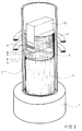
- Fig. 3 shows the structure of this soldering device.
- a quartz tube 2 is attached to a steel base plate 1.
- the lower part of the quartz tube is filled with a cylinder 3 made of Al2O3, which serves as thermal insulation.
- the tungsten component 5, the amorphous Ni / Ti foil 6, the niobium foil 7, a further Ni / Ti foil 8 and the ceramic component 9 are inserted into this fitting slot and by means of a suitable stamp 10, which presses of 0.2 MPa, weighed down.
- the graphite matrix 4 holds the parts to be soldered in position and guides the press ram 10.
- the die 4 itself is surrounded by a graphite susceptor (not shown in the figure), in which the required heating power is generated by means of a high-frequency coil 11.
- a resistance heater could also be used as the heater.
- the quartz glass tube 2 contained an argon atmosphere during the soldering process.
- the soldering temperature in the range of 1255 to 1300 ° C is started with a heating rate of 100 ° C / min. It has proven itself to hold for 10 minutes at about 1000 ° C provide good temperature compensation. A service life of at least 5 seconds must be observed at the soldering temperature. Standing times of up to 3 minutes deliver good results.
- the minimum contact pressure is 0.2 MPa. However, a pressure in the range from 0.35 to 0.7 MPa is preferred. These pressures are generated by applying a weight at the beginning of the soldering process. If a press is used, it is sufficient to apply the pressure only above 1000 ° C.
- the mixture is cooled to 1000 ° C. in about 2 minutes. This ends the alloying processes in the soldering zone as defined as possible. With a holding time of a few minutes at 1000 ° C, however, another possibility for voltage equalization is created.
- the temperature is then lowered at a rate of 50 ° C./min and the sample obtained is removed from the die.
- the temperature is monitored using a built-in thermocouple.
- Niobium has thus reached the tungsten-cobalt alloy through the liquid solder phase. This is followed by a two-phase zone (Zone 3), in which grains with approx. 70 at% niobium are embedded in a phase with less than 50 at% niobium, which also contains 40 at% Ni-Ti.
- a fourth zone was created by solder penetrating the niobium along the grain boundaries.
- the attack remains limited, however, so that eventually a residue of pure niobium (Zone 5) is available.
- Zone 5 pure niobium
- the composition corresponds approximately to that of zone 3. However, about 10 at.% Aluminum are still dissolved in it.
- Zones 1 and 2 have a hardness close to that of the pure tungsten / cobalt alloy.
- Zone 3 with a Vickers hardness of 5592 MPa [570 kp / mm2] can be described as hard, but not yet as a brittle phase.
- Zone 4 with 2747 MPa [280 kp / mm2] comes close to the hardness of pure niobium with 1128 MPa [115 kp / mm2].
- a hardness of approx. 7848 MPa [800 kp / mm2] was measured in the zone adjacent to the aluminum oxide. In all hardness measurements, the measurement of the diagonals of the pyramid impression gave no indication of internal stresses in the contact area with the brittle oxide ceramic.
- the lower limit of the soldering temperature was 1255 ° C with a contact pressure of 0.2 MPa.
- the minimum pressure of 0.2 MPa is required to push gas bubbles that were trapped when the solder melted out of the solder area. At the same time, the pressure causes an even contact and thus a more uniform and faster reaction of the solder with the ceramic, which is slower than the alloy formation with the niobium.
- the working temperature can be reduced even further by using higher pressures.
- solder is pressed out of the seam area by a higher contact pressure and the possibility of brittle phase formation is reduced. In this context, it is advantageous if even thinner foils of the solder are used.
Abstract
Description
Die Erfindung betrifft ein Verfahren zum Verbinden einer Komponente aus Oxidkeramik mit einer metallischen Komponente, entsprechend dem Oberbegriff des 1. Patentanspruches und ein Werkzeug, bestehend aus einer Komponente aus einem Metall der 6. Nebengruppe, bei dem die beiden Komponenten durch eine Zwischenschicht verbunden sind.The invention relates to a method for connecting a component made of oxide ceramic to a metallic component, and a tool consisting of a component made of a metal of subgroup 6, in which the two components are connected by an intermediate layer.
Oxidkeramische Werkstoffe zeichnen sich gegenüber den Metallen durch ihre Härte, Verschleißfestigkeit und Temperaturbeständigkeit sowie durch höhere Beständigkeit gegen Erosion und Korrosion aus. In vielen Fällen stehen jedoch ihrem Einsatz im Maschinenbau und in der Verfahrenstechnik die nachteiligen Eigenschaften wie Sprödigkeit, geringe Biegebruchfestigkeit und Temperaturwechselbeständigkeit im Wege. Deshalb gibt es besonders in der letzten Zeit große Anstrengungen die Eigenschaften von Keramik und Metall zu verbinden, um die Vorzüge beider Materialien besser nutzen zu können. Das führte zur Entwicklung von Verbundwerkstoffen und keramischen Überzügen auf Metallen sowie zu Verbindungen zwischen keramischen und metallischen Bauteilen. Ein bekanntes Beispiel für die Verbindungstechnik ist der Einsatz von keramischen Schneidplatten auf einem metallischen Werkzeugträger.Oxide-ceramic materials are distinguished from metals by their hardness, wear resistance and temperature resistance as well as by their higher resistance to erosion and corrosion. In many cases, however, their use in mechanical engineering and process engineering is hampered by the disadvantageous properties such as brittleness, low flexural strength and resistance to temperature changes. That is why there has been a great deal of effort recently to combine the properties of ceramics and metal in order to better utilize the advantages of both materials. This led to the development of composite materials and ceramic coatings on metals as well as connections between ceramic and metallic components. A well-known example of the connection technology is the use of ceramic cutting inserts on a metallic tool holder.
Aus "A Review of Oxide, Silicon Nitride, and Silicon Carbide Brazing" von M. L. Santella und A. J. Moorhead, Oak Ridge National Laboratory, USA, CONF-870981--1, sind Löt-Verfahren zur Verbindung von Oxidkeramiken wie Aluminiumoxid und Zirkondioxid mit Metallen bekannt. Als Beispiel wird die Verbindung von Keramik mit Gußeisen erwähnt. Verbindungen zwischen Oxidkeramiken und Metallen der 6. Nebengruppe (Chrom, Molybdän, Wolfram) werden nicht angesprochen.From "A Review of Oxide, Silicon Nitride, and Silicon Carbide Brazing" by ML Santella and AJ Moorhead, Oak Ridge National Laboratory, USA, CONF-870981--1, there are soldering processes for connecting oxide ceramics such as aluminum oxide and zirconium dioxide with metals known. The connection of ceramics with cast iron is mentioned as an example. Connections between oxide ceramics and metals of subgroup 6 (chromium, molybdenum, tungsten) are not addressed.
In dieser Veröffentlichung wird darauf hingewiesen, daß die Keramik mit einer benetzenden Metallisierungsschicht überzogen werden muß. Als benetzende Schicht kommen prinzipiell die Elemente Titan, Zirkonium, Aluminium, Lithium und besonders deren Legierungen infrage.In this publication it is pointed out that the ceramic is coated with a wetting metallization layer must become. In principle, the elements titanium, zirconium, aluminum, lithium and especially their alloys are suitable as the wetting layer.
Es wird weiterhin darauf hingewiesen, daß die meisten dieser Legierungen nicht für die kommerzielle Anwendung entwickelt wurden.It should also be noted that most of these alloys have not been developed for commercial use.
In der gleichen Veröffentlichung wird eine Ausgleichsschicht vorgeschlagen, die zwischen die erste (Metallisierungs-) Schicht und die dritte (Löt-) Schicht eingebracht wird, um Unterschiede in den thermischen Ausdehnungskoeffizienten von Metall und Keramik auszugleichen. Als Material für eine solche Schicht werden u. a. Wolfram und Titan vorgeschlagen.In the same publication, a compensation layer is proposed which is introduced between the first (metallization) layer and the third (solder) layer in order to compensate for differences in the thermal expansion coefficients of metal and ceramic. As a material for such a layer u. a. Tungsten and titanium suggested.
Aus H. W. Grünling, "Hochtemperaturbeständige Keramik-Metall-Verbindungen", Schweißen + Schneiden, Jahrgang 25 (1973), Heft 2, Seiten 52 bis 55 ist der Verbund von Werkstoffen aus Al₂O₃-Keramik und Wolfram, Molybdän oder Niob bekannt, der auf folgende Weise hergestellt wurde:From HW Grünling, "High-temperature resistant ceramic-metal connections", welding + cutting, year 25 (1973),
Auf der Keramikschicht wird durch Gasphasenabscheidung eines dünnen Niob- oder Wolframfilms eine elektrisch leitende Metallisierungsschicht erzeugt, die durch eine aus einer Fluoridschmelze bei 740° C abgeschiedene Niobschicht überdeckt wird. Auf diese Schicht werden hochtemperaturbeständige Metalle wie Wolfram, Molybdän oder Niob aufgelötet.An electrically conductive metallization layer is produced on the ceramic layer by vapor deposition of a thin niobium or tungsten film, which is covered by a niobium layer deposited from a fluoride melt at 740 ° C. High-temperature resistant metals such as tungsten, molybdenum or niobium are soldered onto this layer.
Als Nachteil wird das aufwendige Fertigungsverfahren angegeben.The complex manufacturing process is stated as a disadvantage.
Aus dieser Veröffentlichung geht weiter hervor, daß auf das Metallisieren der Keramik verzichtet werden kann, wenn man Aktivlote aus Titan und Zirkonium oder deren Legierungen mit Kupfer oder Silber verwendet.From this publication it is further evident that the metallization of the ceramic can be dispensed with if active solders made of titanium and zirconium or their alloys with copper or silver are used.
Charakteristisch für diese Aktivmetalle ist ihre große Affinität gegenüber Sauerstoff, durch die die günstigen Bindeeigenschaften erklärt werden.These active metals are characterized by their high affinity for oxygen, which explains the favorable binding properties.
Gleichzeitig wird darauf hingewiesen, daß diese Aktivmetalle bevorzugt spröde intermetallische Phasen mit dem Metallpartner bilden, wodurch die Verbindung gegen Wärmespannungen empfindlich wird, und daß die Lote die Neigung zeigen, sich über die ganze Oberfläche der Keramik auszubreiten, wodurch die Begrenzung des Lotes auf die Fügestelle erschwert, vielfach sogar verhindert wird. Deshalb wird die Verwendung von komplexen, im Benetzungsverhalten abgestimmten Loten empfohlen.At the same time, it is pointed out that these active metals preferentially form brittle intermetallic phases with the metal partner, which makes the connection sensitive to thermal stresses, and that the solders show a tendency to spread over the entire surface of the ceramic, thereby limiting the solder to the joint difficult, in many cases even prevented. For this reason, the use of complex solders that are matched to their wetting behavior is recommended.
Aus K. Suganuma, T. Okamoto und M. Koizumi, "Effect of Inter-layers in Ceramic-Metal Joints with Thermal Expansion Mismatches", Communinizations of the American Ceramic Society, December 1984, p. C-256 - C-257 ist ferner eine Niob-Ausgleichsschicht bekannt geworden. Diese Schicht wird jedoch zur Verbindung von Stahl und Keramik vorgeschlagen.From K. Suganuma, T. Okamoto and M. Koizumi, "Effect of Inter-layers in Ceramic-Metal Joints with Thermal Expansion Mismatches", Communinizations of the American Ceramic Society, December 1984, p. C-256 - C-257 a niobium compensation layer has also become known. However, this layer is proposed for the connection of steel and ceramic.
Weiterhin sind zur Herstellung der Verbindung von Stahl und Keramik mit der Niob-Ausgleichsschicht Drücke von 100 MPa erforderlich.Furthermore, pressures of 100 MPa are required to produce the connection between steel and ceramic with the niobium compensation layer.
Der Erfindung liegt die Aufgabe zugrunde, ein Verfahren zur Herstellung eines Werkzeugs anzugeben, in dem die günstigen Eigenschaften von Metall und Keramik kombiniert sind. Die Keramik soll durch ein hartes Metall wirkungsvoll unterstützt werden, wobei die Verbindungsstelle von Keramik und hartem Metall in der Lage ist, die unterschiedliche Temperaturausdehnung zu kompensieren. Das Werkzeug soll durch ein einfaches Verfahren mit einem einzigen Verfahrensschritt herstellbar sein. Inbesondere soll das Verfahren keine Anwendung hoher Drücke und somit einer Hochdruck-Preßvorrichtung bedingen. Die Verbindung soll temperaturwechselbeständig sein und nicht zur Ausbildung von Sprödphasen neigen.The invention has for its object to provide a method for producing a tool in which the favorable properties of metal and ceramic are combined. The ceramic is to be effectively supported by a hard metal, the connection point of ceramic and hard metal being able to compensate for the different temperature expansion. The tool should be able to be produced by a simple method with a single method step. In particular, the method should not be used high pressures and thus a high pressure press. The connection should be resistant to temperature changes and should not tend to form brittle phases.
Die Aufgabe wird erfindungsgemäß durch ein Verfahren mit den im Kennzeichen des ersten Patentanspruches und durch ein Werkzeug mit den im Kennzeichen des siebten Patentanspruches aufgeführten Merkmalen gelöst.The object is achieved by a method with the features listed in the characterizing part of the first claim and by a tool with the features listed in the characterizing part of the seventh claim.
Die Erfindung schlägt ein einfaches Verfahren vor, um Metalle der 6. Nebengruppe, insbesondere Wolfram, mit Oxidkeramiken, insbesondere Aluminiumoxid zu verbinden. Dabei ist es im Gegensatz zum Stand der Technik unerheblich, ob das Aluminiumoxid rein oder als Mischkristall mit anderen Stoffen vorliegt. Als oxidkeramik kann auch Zirkonoxid mit Zusätzen von oxiden, Karbiden, Boriden und Nitriden verwendet werdenThe invention proposes a simple method for joining metals of subgroup 6, in particular tungsten, with oxide ceramics, in particular aluminum oxide. In contrast to the prior art, it is irrelevant whether the aluminum oxide is pure or as a mixed crystal with other substances. Zirconium oxide with additions of oxides, carbides, borides and nitrides can also be used as the oxide ceramic
Bei der Verwendung von Metallpulver sollte die Schichtdicke der ersten und dritten Schicht etwa bis zu 100 µm betragen.When using metal powder, the layer thickness of the first and third layers should be approximately up to 100 µm.
In einer bevorzugten Ausführungsform des erfindungsgemäßen Verfahrens werden für die erste und dritte Schicht Folien einer amorphen Ni/Ti-Legierung verwendet.In a preferred embodiment of the method according to the invention, foils of an amorphous Ni / Ti alloy are used for the first and third layers.
Die Dicke der Folien für die erste und dritte Schicht sollte 30 µm nicht übersteigen. Dünnere Schichten erweisen sich als vorteilhaft. Eine untere Grenze für die Folienschichtdicke bildet die Oberflächenrauhigkeit der Komponenten, insbesondere der Oxidkeramik.The thickness of the films for the first and third layers should not exceed 30 µm. Thinner layers prove to be advantageous. A lower limit for the film layer thickness is the surface roughness of the components, in particular the oxide ceramic.
Für die Dicke der Niobschicht kann als Bemessungsgrundlage ein Wert von 50 µm zuzüglich der Folienstärke der ersten Schicht angenommen werden. Gute Ergebnisse werden jedoch auch mit etwas dickeren Folien, etwa bis 100 µm, erzielt.For the thickness of the niobium layer, a value of 50 µm plus the film thickness of the first layer can be assumed as the basis for assessment. However, good results are also achieved with somewhat thicker films, approximately up to 100 µm.
Die Folien sollten in ihrer Struktur amorph sein; sie werden beispielsweise nach dem in der Offenlegungsschrift DE 35 18 706 beschriebenen Verfahren aus amorphen Pulvern geeigneter Zusammensetzung gepreßt und gesintert. Vorteilhaft ist hierbei, daß die Folien mit einer Schere auf das gewünschte Maß zugeschnitten werden können.The structure of the foils should be amorphous; for example, they become more suitable from amorphous powders according to the process described in published patent application DE 35 18 706 Composition pressed and sintered. It is advantageous here that the foils can be cut to the desired size with scissors.
Als Material für die erste und dritte Zwischenschicht wird eine amorphe Nickel/Titan-Legierung verwendet, die 35 bis 60 Atom-% Nickel enthält.An amorphous nickel / titanium alloy containing 35 to 60 atom% of nickel is used as the material for the first and third intermediate layers.
Fig. 1 zeigt das Schmelzdiagramm des Systems Nickel/Titan.1 shows the melting diagram of the nickel / titanium system.
Diesem Schmelzdiagramm kann der jeweilige Schmelzpunkt der Legierung entnommen werden.The respective melting point of the alloy can be seen from this melting diagram.
Bei der erfindungsgemäßen Legierungszusammensetzung wird einerseits die Ausbildung von Sprödphasen, die sich insbesondere bei einem Nickel-Anteil von etwa 25 bis 30 % ausbilden, weitgehend ausgeschlossen; andererseits ist der Schmelzpunkt gegenüber dem bekannten TiNi₃-Lot deutlich vermindert. Besonders bevorzugt ist der Bereich, der der Flanke der Schmelzpunktskurve zwischen etwa 35 und 45 Atom-% Nickel entspricht. Gut geeignet ist eine Legierung, die 40 Atom-% Nickel und 60 Atom-% Titan enthält.With the alloy composition according to the invention, on the one hand, the formation of brittle phases, which form in particular with a nickel content of about 25 to 30%, is largely ruled out; on the other hand, the melting point is significantly reduced compared to the known TiNi₃ solder. The range which corresponds to the flank of the melting point curve between about 35 and 45 atom% of nickel is particularly preferred. An alloy which contains 40 atom% of nickel and 60 atom% of titanium is very suitable.
Als Ausgleichsmaterial zur Kompensation der verschiedenen Ausdehnungkoeffizienten von Keramik und dem Metall der 6. Nebengruppe eignet sich reines Niob oder Niob-Basislegierungen in Folienform, soweit durch Legierungszusätze die plastischen Eigenschaften von Niob nicht wesentlich verschlechtert werden.Pure niobium or niobium base alloys in foil form are suitable as compensation material to compensate for the different expansion coefficients of ceramic and the metal of subgroup 6, provided that the plastic properties of niobium are not significantly impaired by alloy additives.
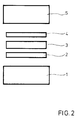
Fig. 2 zeigt die erfindungsgemäße Anordnung von Komponenten und Zwischenschichten.2 shows the arrangement of components and intermediate layers according to the invention.
Auf eine Komponente aus Oxidkeramik 1 wird eine Ni/Ti-Folie 2 geeigneter Größe aufgelegt. Auf dieser Folie wird eine Folie aus Niob oder einer Niob-Basislegierung 3 aufgelegt, die von einer weiteren Ni/Ti-Folie 4 abgedeckt wird.A Ni /
Die Größe und Anordnung der Folien entspricht der gewünschten Verbindungsfläche der keramischen und der metallischen Komponente 5.The size and arrangement of the foils corresponds to the desired connecting area of the ceramic and the
Auf die letztgenannte Folie wird die metallische Komponente 5 aufgelegt.The
Auf die metallische Komponente wird ein Gewicht, das einen Druck von mindestens 0,2 MPa auf die Verbindungsstelle ausübt, aufgelegt, sofern das Eigengewicht der metallischen Komponente nicht ausreicht.A weight that exerts a pressure of at least 0.2 MPa on the connection point is placed on the metallic component, provided the weight of the metallic component is not sufficient.
Der Druck kann auch durch eine einfache Preßvorrichtung ausgeübt werden. Eine Hochdruck-Preßvorrichtung ist unnötig.The pressure can also be applied by a simple pressing device. A high pressure press device is unnecessary.
Die Anordnung der Komponenten und Folien kann in einem Graphit-Induktionsofen erfolgen, der bei geeigneter Geometrie zugleich ein Verschieben der Anordnung verhindert.The components and foils can be arranged in a graphite induction furnace which, with a suitable geometry, also prevents the arrangement from shifting.
Anschließend wird die Anordnung unter Schutzgasatmosphäre zumindest auf die Schmelztemperatur der Ni/Ti-Legierung, vorzugsweise auf etwa 1255° bis 1300° C, aufgeheizt. Die Heizzeit beträgt etwa 30 Sekunden.The arrangement is then heated under a protective gas atmosphere at least to the melting temperature of the Ni / Ti alloy, preferably to about 1255 ° to 1300 ° C. The heating time is about 30 seconds.
Die verbundenen Komponenten werden langsam abgekühlt und der Heizvorrichtung entnommen.The connected components are slowly cooled and removed from the heater.
Die Erfindung wird im folgenden anhand eines Durchführungsbeispiels näher erläutert.The invention is explained in more detail below with the aid of an exemplary embodiment.
Von einem Schneidplättchen aus Al₂O₃ mit TiC wurde ein Stück mit den Dimensionen 2 x 2 x 8 mm³ mit einer Diamantsäge abgetrennt. Ebenso wurde aus einem Wolfram-Band ein Teil mit den Abmessungen 2 x 2 x 8 mm³ abgesägt.From a cutting plate made of Al₂O₃ with TiC a piece with the dimensions 2 x 2 x 8 mm³ was cut off with a diamond saw. A part with the dimensions 2 x 2 x 8 mm³ was also sawn off from a tungsten band.
Aus 40 % Ni, Rest Titan wurden entsprechend der DE-OS 35 18 706 zwei Folienstücke der Dimension 2 x 8 mm² hergestellt. Die Dicke der Folien betrug 30 µm. Aus einer Niob-Folie der Dicke 100 µm wurde ein Teilstück mit 2 x 8 mm² herausgeschnitten.Two pieces of foil measuring 2 x 8 mm² were produced from 40% Ni, the rest of titanium in accordance with DE-OS 35 18 706. The thickness of the foils was 30 µm. A section with 2 x 8 mm² was cut out of a niobium foil with a thickness of 100 µm.
Die Verbindung der Wolfram-Komponente mit der Keramik-Komponente erfolgte in einer Lötvorrichtung.The tungsten component was connected to the ceramic component in a soldering device.
Fig. 3 zeigt den Aufbau dieser Lötvorrichtung.Fig. 3 shows the structure of this soldering device.
Auf einer Grundplatte 1 aus Stahl ist ein Quarzrohr 2 befestigt. Der untere Teil des Quarzrohrs ist mit einem Zylinder 3 aus Al₂O₃ gefüllt, der als thermische Isolation dient. Auf diesem Isolator steht ein Zylinder aus Graphit 4, der in seinem oberen Ende einen Paßschlitz zur Aufnahme der Komponenten und der Folienstücke enthält. In diesem Paßschlitz werden die Wolfram-Komponente 5, die amorphe Ni/Ti-Folie 6, die Niob-Folie 7, eine weitere Ni/Ti-Folie 8 und die Keramik-Komponente 9 eingelegt und durch einen passenden Stempel 10, der einen Druck von 0,2 MPa ausübt, beschwert.A
Die Graphit-Matrize 4 hält die zu lötenden Teile in ihrer Position und führt den Preßstempel 10.The
Die Matrize 4 selbst ist von einem (in der Figur nicht dargestellten) Graphit-Suszeptor umgeben, in dem mittels einer Hochfrequenz-Spule 11 die erforderliche Heizleistung erzeugt wird. Als Heizung könnte jedoch auch eine Widerstandsheizung verwendet werden. Das Quarzglasrohr 2 enthielt während des Lötprozesses eine Argonatmosphäre.The
Die Löttemperatur im Bereich von 1255 bis 1300° C wird mit einer Aufheizrate von 100° C/min angefahren. Es hat sich bewährt, bei etwa 1000° C eine Haltezeit von 10 min für einen guten Temperaturausgleich vorzusehen. Bei der Löttemperatur ist eine Standzeit von wenigstens 5 Sekunden einzuhalten. Standzeiten bis zu 3 Minuten liefern gute Ergebnisse.The soldering temperature in the range of 1255 to 1300 ° C is started with a heating rate of 100 ° C / min. It has proven itself to hold for 10 minutes at about 1000 ° C provide good temperature compensation. A service life of at least 5 seconds must be observed at the soldering temperature. Standing times of up to 3 minutes deliver good results.
Als minimaler Anpreßdruck sind 0,2 MPa vorzusehen. Bevorzugt wird jedoch ein Druck im Bereich von 0,35 bis 0,7 MPa. Diese Drücke werden durch Auflegen eines Gewichtes zu Beginn des Lötprozesses erzeugt. Verwendet man eine Presse, so genügt es, den Druck erst oberhalb von 1000° C aufzubringen.The minimum contact pressure is 0.2 MPa. However, a pressure in the range from 0.35 to 0.7 MPa is preferred. These pressures are generated by applying a weight at the beginning of the soldering process. If a press is used, it is sufficient to apply the pressure only above 1000 ° C.
Nach Ende der Lötstandzeit wird innerhalb von etwa 2 Minuten auf 1000° C abgekühlt. Damit werden die Legierungsvorgänge in der Lötzone möglichst definiert beendet. Mit einer Haltezeit von wenigen Minuten bei 1000° C wird jedoch nochmals eine Möglichkeit für den Spannungsausgleich geschaffen.After the soldering life has ended, the mixture is cooled to 1000 ° C. in about 2 minutes. This ends the alloying processes in the soldering zone as defined as possible. With a holding time of a few minutes at 1000 ° C, however, another possibility for voltage equalization is created.
Anschließend wird die Temperatur bei einer Rate von 50° C/min erniedrigt und die erhaltene Probe der Matrize entnommen.The temperature is then lowered at a rate of 50 ° C./min and the sample obtained is removed from the die.
Die Temperaturüberwachung erfolgt mit Hilfe eines eingebauten Thermoelements.The temperature is monitored using a built-in thermocouple.
Von der auf diese Weise hergestellten Probe wurde ein Schliffbild angefertigt.A micrograph was made of the sample produced in this way.
In unmittelbarer Nachbarschaft zum Wolfram befinden sich zwei Zonen, die aus einer W-Co-Ni-Legierung bestehen. Niob ist also durch die flüssige Lotphase zur Wolfram-Cobalt-Legierung gelangt. Es schließt sich eine zweiphasige Zone (Zone 3) an, in der Körner mit ca. 70 At% Niob in eine Phase mit weniger als 50 At% Niob eingebettet sind, die außerdem noch 40 At% Ni-Ti enthält.There are two zones in the immediate vicinity of the tungsten, which consist of a W-Co-Ni alloy. Niobium has thus reached the tungsten-cobalt alloy through the liquid solder phase. This is followed by a two-phase zone (Zone 3), in which grains with approx. 70 at% niobium are embedded in a phase with less than 50 at% niobium, which also contains 40 at% Ni-Ti.
Eine 4. Zone entstand durch Lot, das entlang der Korngrenzen in das Niob eingedrungen ist. Der Angriff bleibt jedoch begrenzt, so daß schließlich ein Rest von reinem Niob (Zone 5) vorhanden ist. In Nachbarschaft zum Aluminiumoxid gibt es wieder eine mehrphasige Struktur. Die Zusammensetzung entspricht etwa der der Zone 3. Darin sind jedoch noch ca. 10 At.-% Aluminium gelöst.A fourth zone was created by solder penetrating the niobium along the grain boundaries. The attack remains limited, however, so that eventually a residue of pure niobium (Zone 5) is available. In the vicinity of the aluminum oxide there is again a multi-phase structure. The composition corresponds approximately to that of
Zonen 1 und 2 besitzen eine Härte, die nahe der der reinen Wolfram/Kobalt-Legierung ist. Zone 3 kann mit einer Vickershärte von 5592 MPa [570 kp/mm²] als hart, jedoch noch nicht als Sprödphase bezeichnet werden. Zone 4 kommt mit 2747 MPa [280 kp/mm²] nahe an die Härte des reinen Niobs mit 1128 MPa [115 kp/mm²].
In der dem Aluminiumoxid benachbarten Zone wurde eine Härte von ca. 7848 MPa [800 kp/mm²] gemessen. Bei allen Härtemessungen ergab sich aus der Vermessung der Diagonalen des Pyramidenabdrucks kein Hinweis auf innere Spannungen im Kontaktbereich zu der spröden Oxidkeramik.A hardness of approx. 7848 MPa [800 kp / mm²] was measured in the zone adjacent to the aluminum oxide. In all hardness measurements, the measurement of the diagonals of the pyramid impression gave no indication of internal stresses in the contact area with the brittle oxide ceramic.
Die Erniedrigung der Arbeitstemperatur sowie verkürzte Standzeiten oberhalb des Lotschmelzpunktes ergaben, daß es möglich ist, die Ausdehnung der härteren Zonen 3 und 6 zu reduzieren sowie deren Härte auf etwa 5886 MPa [600 kp/mm²] in Zone 6 zu verringern.The lowering of the working temperature and the shortened service life above the solder melting point showed that it is possible to reduce the extent of the
Die Untergrenze der Löttemperatur ergab sich zu 1255° C bei einem Anpreßdruck von 0.2 MPa. Der Mindestdruck von 0.2 MPa ist erforderlich, um Gasblasen, die beim Schmelzen des Lots eingeschlossen wurden, aus dem Lotbereich zu drücken. Gleichzeitig bewirkt der Druck einen gleichmäßigen Kontakt und damit eine gleichmäßigere und schnellere Reaktion des Lots mit der Keramik, die langsamer abläuft als die Legierungsbildung mit dem Niob.The lower limit of the soldering temperature was 1255 ° C with a contact pressure of 0.2 MPa. The minimum pressure of 0.2 MPa is required to push gas bubbles that were trapped when the solder melted out of the solder area. At the same time, the pressure causes an even contact and thus a more uniform and faster reaction of the solder with the ceramic, which is slower than the alloy formation with the niobium.
Durch Anwendung höherer Drücke kann die Arbeitstemperatur noch weiter verringert werden. Außerdem wird durch einen höheren Anpreßdruck Lot aus dem Nahtbereich gedrückt und die Möglichkeit zur Sprödphasenbildung reduziert. Von Vorteil ist in diesem Zusammenhang, wenn noch dünnere Folien des Lots verwendet werden.The working temperature can be reduced even further by using higher pressures. In addition, solder is pressed out of the seam area by a higher contact pressure and the possibility of brittle phase formation is reduced. In this context, it is advantageous if even thinner foils of the solder are used.
Claims (8)
- Technique for bonding a component made of oxide ceramic with a metallic component with(a) a first layer made from a titanium alloy applied onto the oxide ceramic,(b) the first metallic layer covered by a second metallic layer,(c) the metallic component soldered on by means of a third metallic layer containing nickel and titanium,
characterized in that(d) a component made of a metal or metal base alloy of the 6. subgroup is used as the metallic component;(e) nickel powder and titanium powder, mixed at a ratio of 35 to 60 at.% nickel and 65 to 40 at.% titanium, are used for the first and third layers;(f) a foil of niobium or niobium base alloy is used to constitute the second layer;(g) the bonding of the component made of oxide ceramic with the surface of the metallic component is effected in one single process step via the layers in-between, by. arranging the components and the metallic layers one above the other in the manner indicated;. generating at the point of bonding of the components a pressure of at least 0.2 MPa;. bonding the components in cover gas atmosphere by heating them to a temperature corresponding to at least the melting temperature of the first and third layers. - Technique as claimed in 1 with pure alumina used as oxide ceramic.
- Technique as claimed in 1 with an oxide ceramic used which is made of alumina with oxides, carbides, borides and nitrides added.
- Technique as claimed in 1 with an oxide ceramic used which is made of zirconium oxide with oxides, carbides, borides and nitrides added.
- Technique as claimed in 1 through 4 with a foil made of amorphous Ni/Ti alloy containing 35 to 60 at.% nickel and 65 to 40 at.% titanium used as the first and third layers.
- Technique as claimed in one of the claims 1 to 5 with the first and third layers consisting of 40 at.% nickel and 60 at.% titanium.
- Technique as claimed in one of the claims 1 through 6 with the components to be bonded compressed in the course of bonding by application of a suitable weight.
- Tool consisting of a component made of oxide ceramic and a metallic component made of a metal of the 6. subgroup in which both components are bonded by an intermediate layer characterized in that the intermediate layer consists of two layers of a nickel-titanium alloy with 35 to 60 at.% nickel and a layer of niobium or niobium base alloy arranged in-between, with the ends of layers interconnected by transition zones.
Priority Applications (1)
| Application Number | Priority Date | Filing Date | Title |
|---|---|---|---|
| AT90104088T ATE89538T1 (en) | 1989-03-20 | 1990-03-02 | METHOD OF JOINING OXIDE CERAMIC AND METAL AND TOOL MANUFACTURED THEREFORE. |
Applications Claiming Priority (2)
| Application Number | Priority Date | Filing Date | Title |
|---|---|---|---|
| DE3909088 | 1989-03-20 | ||
| DE3909088A DE3909088C1 (en) | 1989-03-20 | 1989-03-20 |
Publications (2)
| Publication Number | Publication Date |
|---|---|
| EP0388685A1 EP0388685A1 (en) | 1990-09-26 |
| EP0388685B1 true EP0388685B1 (en) | 1993-05-19 |
Family
ID=6376760
Family Applications (1)
| Application Number | Title | Priority Date | Filing Date |
|---|---|---|---|
| EP90104088A Expired - Lifetime EP0388685B1 (en) | 1989-03-20 | 1990-03-02 | Process for joining oxide ceramics and metal and tool produced hereby |
Country Status (3)
| Country | Link |
|---|---|
| EP (1) | EP0388685B1 (en) |
| AT (1) | ATE89538T1 (en) |
| DE (1) | DE3909088C1 (en) |
Cited By (1)
| Publication number | Priority date | Publication date | Assignee | Title |
|---|---|---|---|---|
| DE102019121936A1 (en) * | 2019-08-14 | 2021-02-18 | Technische Universitaet Dresden | High temperature active solders |
Families Citing this family (1)
| Publication number | Priority date | Publication date | Assignee | Title |
|---|---|---|---|---|
| WO2007001392A2 (en) | 2004-10-01 | 2007-01-04 | The Regents Of The University Of Michigan | Manufacture of shape-memory alloy cellular meterials and structures by transient-liquid reactive joining |
Family Cites Families (2)
| Publication number | Priority date | Publication date | Assignee | Title |
|---|---|---|---|---|
| DE3014645C2 (en) * | 1980-04-16 | 1982-12-02 | MTU Motoren- und Turbinen-Union München GmbH, 8000 München | Metal-ceramic component and process for its manufacture |
| DE3518706A1 (en) * | 1985-05-24 | 1986-11-27 | Kernforschungszentrum Karlsruhe Gmbh, 7500 Karlsruhe | METHOD FOR PRODUCING MOLDED BODIES WITH IMPROVED ISOTROPICAL PROPERTIES |
-
1989
- 1989-03-20 DE DE3909088A patent/DE3909088C1/de not_active Expired - Fee Related
-
1990
- 1990-03-02 EP EP90104088A patent/EP0388685B1/en not_active Expired - Lifetime
- 1990-03-02 AT AT90104088T patent/ATE89538T1/en not_active IP Right Cessation
Cited By (1)
| Publication number | Priority date | Publication date | Assignee | Title |
|---|---|---|---|---|
| DE102019121936A1 (en) * | 2019-08-14 | 2021-02-18 | Technische Universitaet Dresden | High temperature active solders |
Also Published As
| Publication number | Publication date |
|---|---|
| DE3909088C1 (en) | 1990-08-30 |
| ATE89538T1 (en) | 1993-06-15 |
| EP0388685A1 (en) | 1990-09-26 |
Similar Documents
| Publication | Publication Date | Title |
|---|---|---|
| CA1322662C (en) | Brazed thermally-stable polycrystalline diamond compact workpieces and their fabrication | |
| US4710235A (en) | Process for preparation of liquid phase bonded amorphous materials | |
| EP1233935B1 (en) | Method for attaching a body, which is comprised of a metal matrix composite (mmc) material, to a ceramic body | |
| EP1601631A1 (en) | Method for producing a composite material | |
| EP1250467B1 (en) | Soldering alloy | |
| EP1751320A1 (en) | Wearing part consisting of a diamantiferous composite | |
| EP0209672B1 (en) | Method of bonding silicon carbide bodies | |
| DE3608559A1 (en) | METHOD FOR JOINING SIC MOLDED PARTS WITH CERAMIC OR METAL AND FOR TREATING SISIC SURFACES, AND AN ALLOY ALLOY | |
| EP1678733B1 (en) | Method for production of a composite body by high temperature welding of a non-metallic component to a metallic or non-metallic component | |
| EP1632463A1 (en) | Composite material | |
| DE3622192A1 (en) | OXYDATION-RESISTANT FILL METALS FOR THE DIRECT HARD SOLDERING OF CERAMIC COMPONENTS | |
| EP0388685B1 (en) | Process for joining oxide ceramics and metal and tool produced hereby | |
| DE2534777C2 (en) | Method for soldering a polycrystalline body made of extremely hard material based on boron nitride and / or diamond with a metal part and solder for carrying out this method | |
| CA1229507A (en) | Nickel based brazing filler metals | |
| Su et al. | Al 2 O 3/SUS304 brazing via AgCuTi-W composite as active filler | |
| DE3933215C1 (en) | ||
| He et al. | The effect of Mo particles addition in Ag-Cu-Ti filler alloy on Ti (C, N)-based cermet/45 steel-brazed joints | |
| Ljungberg et al. | Wetting of silicon nitride with selected metals and alloys | |
| DE102004020404A1 (en) | Support plate for sputtering targets | |
| EP0730929B1 (en) | Use of brazing alloy for bonding carbonaceous body and carbonaceous body coated with hard layer | |
| EP3577249A1 (en) | Method for coating solid diamond materials | |
| DE4024518A1 (en) | THERMALLY STABLE BORNITRIDE PRESSELS AND METHOD FOR THE PRODUCTION THEREOF | |
| WO2021028283A1 (en) | High-temperature active solders | |
| JPS6332759B2 (en) | ||
| Park et al. | Microstructure and Reactions of SiCw‐Reinforced Alumina with Ag‐Cu‐In‐Ti |
Legal Events
| Date | Code | Title | Description |
|---|---|---|---|
| PUAI | Public reference made under article 153(3) epc to a published international application that has entered the european phase |
Free format text: ORIGINAL CODE: 0009012 |
|
| AK | Designated contracting states |
Kind code of ref document: A1 Designated state(s): AT BE CH FR GB IT LI NL SE |
|
| 17P | Request for examination filed |
Effective date: 19901029 |
|
| 17Q | First examination report despatched |
Effective date: 19920928 |
|
| GRAA | (expected) grant |
Free format text: ORIGINAL CODE: 0009210 |
|
| AK | Designated contracting states |
Kind code of ref document: B1 Designated state(s): AT BE CH FR GB IT LI NL SE |
|
| PG25 | Lapsed in a contracting state [announced via postgrant information from national office to epo] |
Ref country code: IT Free format text: LAPSE BECAUSE OF FAILURE TO SUBMIT A TRANSLATION OF THE DESCRIPTION OR TO PAY THE FEE WITHIN THE PRE;WARNING: LAPSES OF ITALIAN PATENTS WITH EFFECTIVE DATE BEFORE 2007 MAY HAVE OCCURRED AT ANY TIME BEFORE 2007. THE CORRECT EFFECTIVE DATE MAY BE DIFFERENT FROM THE ONE RECORDED.SCRIBED TIME-LIMIT Effective date: 19930519 Ref country code: GB Effective date: 19930519 Ref country code: NL Effective date: 19930519 Ref country code: SE Effective date: 19930519 |
|
| REF | Corresponds to: |
Ref document number: 89538 Country of ref document: AT Date of ref document: 19930615 Kind code of ref document: T |
|
| ET | Fr: translation filed | ||
| NLV1 | Nl: lapsed or annulled due to failure to fulfill the requirements of art. 29p and 29m of the patents act | ||
| GBV | Gb: ep patent (uk) treated as always having been void in accordance with gb section 77(7)/1977 [no translation filed] |
Effective date: 19930519 |
|
| PGFP | Annual fee paid to national office [announced via postgrant information from national office to epo] |
Ref country code: CH Payment date: 19940127 Year of fee payment: 5 |
|
| PLBE | No opposition filed within time limit |
Free format text: ORIGINAL CODE: 0009261 |
|
| STAA | Information on the status of an ep patent application or granted ep patent |
Free format text: STATUS: NO OPPOSITION FILED WITHIN TIME LIMIT |
|
| PGFP | Annual fee paid to national office [announced via postgrant information from national office to epo] |
Ref country code: AT Payment date: 19940329 Year of fee payment: 5 |
|
| PGFP | Annual fee paid to national office [announced via postgrant information from national office to epo] |
Ref country code: FR Payment date: 19940330 Year of fee payment: 5 |
|
| PGFP | Annual fee paid to national office [announced via postgrant information from national office to epo] |
Ref country code: BE Payment date: 19940401 Year of fee payment: 5 |
|
| 26N | No opposition filed | ||
| PG25 | Lapsed in a contracting state [announced via postgrant information from national office to epo] |
Ref country code: AT Effective date: 19950302 |
|
| PG25 | Lapsed in a contracting state [announced via postgrant information from national office to epo] |
Ref country code: CH Effective date: 19950331 Ref country code: BE Effective date: 19950331 Ref country code: LI Effective date: 19950331 |
|
| BERE | Be: lapsed |
Owner name: KERNFORSCHUNGSZENTRUM KARLSRUHE G.M.B.H. Effective date: 19950331 |
|
| PG25 | Lapsed in a contracting state [announced via postgrant information from national office to epo] |
Ref country code: FR Free format text: LAPSE BECAUSE OF NON-PAYMENT OF DUE FEES Effective date: 19951130 |
|
| REG | Reference to a national code |
Ref country code: CH Ref legal event code: PL |
|
| REG | Reference to a national code |
Ref country code: FR Ref legal event code: ST |