EP0388479A1 - Voltage-reactive power control apparatus - Google Patents
Voltage-reactive power control apparatus Download PDFInfo
- Publication number
- EP0388479A1 EP0388479A1 EP89104914A EP89104914A EP0388479A1 EP 0388479 A1 EP0388479 A1 EP 0388479A1 EP 89104914 A EP89104914 A EP 89104914A EP 89104914 A EP89104914 A EP 89104914A EP 0388479 A1 EP0388479 A1 EP 0388479A1
- Authority
- EP
- European Patent Office
- Prior art keywords
- voltage
- power
- load
- reactive power
- power flow
- Prior art date
- Legal status (The legal status is an assumption and is not a legal conclusion. Google has not performed a legal analysis and makes no representation as to the accuracy of the status listed.)
- Granted
Links
Images


Classifications
-
- H—ELECTRICITY
- H02—GENERATION; CONVERSION OR DISTRIBUTION OF ELECTRIC POWER
- H02J—ELECTRIC POWER NETWORKS; CIRCUIT ARRANGEMENTS OR SYSTEMS FOR SUPPLYING OR DISTRIBUTING ELECTRIC POWER; SYSTEMS FOR STORING ELECTRIC ENERGY
- H02J3/00—Circuit arrangements for AC mains or AC distribution networks
- H02J3/18—Arrangements for adjusting, eliminating or compensating reactive power in networks
- H02J3/1821—Arrangements for adjusting, eliminating or compensating reactive power in networks using shunt compensators
-
- Y—GENERAL TAGGING OF NEW TECHNOLOGICAL DEVELOPMENTS; GENERAL TAGGING OF CROSS-SECTIONAL TECHNOLOGIES SPANNING OVER SEVERAL SECTIONS OF THE IPC; TECHNICAL SUBJECTS COVERED BY FORMER USPC CROSS-REFERENCE ART COLLECTIONS [XRACs] AND DIGESTS
- Y02—TECHNOLOGIES OR APPLICATIONS FOR MITIGATION OR ADAPTATION AGAINST CLIMATE CHANGE
- Y02E—REDUCTION OF GREENHOUSE GAS [GHG] EMISSIONS, RELATED TO ENERGY GENERATION, TRANSMISSION OR DISTRIBUTION
- Y02E40/00—Technologies for an efficient electrical power generation, transmission or distribution
- Y02E40/30—Reactive power compensation
Definitions
- the present invention relates to a voltage-reactive power control apparatus in corporated to reactive power supplying equipment for adequately sustaining load side voltages in the power system.
- a voltage of the power system always fluctuates, as is well known, in accordance with change of demand and supply. Large voltage fluctuation affects not only normal application or operation life of a variety of electrical appliances connected to the system, consumers but also insulation design of various power apparatus to be installed in the power system, and moreover results in interferes for stable and efficient operations of the system including a power generator from the viewpoint of operation of the power system. Namely, the voltage-reactive power control is essential for all electrical appliances and power apparatuses connected to the power system to ensure normal operations and for realizing stable and efficient operations of the system.
- the recent power generation plant is in the situation as the far remoted and localized, realization of large scale power generation base through utilization of a large capacity generator unit and long distance and high voltage transmission and heavier power flow in the power transmission facilities.
- a voltage of power system is maintained and adjusted to a preset reference value through the voltage-reactive power control of the generator and phase modifying equipment.
- VAR supply equipments falls a load increases suddenly or demand and supply of the reactive power is unbalanced, voltage of the primary system may abnormally fall or rise under the situation where the power system is grown-up in scale.
- the voltage-reactive power control apparatus of the prior art has mainly assigned monitoring and operation for such voltage variation or voltage abnormalities to the load dispatching center which manages operation of the whole system. Moreover the information coming from the load end is delayed, and synchronized informations are not obtained. Therefore these informations are inaccurate to be used.
- the present invention has been proposed to solve such problems and therefore it is an object of the present invention to provide a voltage-reactive power control apparatus which takes a measure for a local failure and then spreading the range for measure in case when wider area measure required.
- the voltage reactive-power adjusting equipment of the present invention is installed at the principal point of the load area in the power system.
- the equipment first detects the power flow into load and the voltage at the load side with the control and monitoring device within the equipment.
- the rate of change of the power-flow and that of the voltage are calculated from the measured value obtained as above.
- the margin value calculated by the following system data to determine the control signal to VAR supply equipment with proper time delay, where the system data includes short circuit capacity of the power system, the power flow, the load-side voltage, and the voltage stability limit of the system calculated as assumed the load being constant-power load.
- the control signal to the VAR supply equipment has time delay which depends on the ratio of voltage change to VAR supply change.
- the voltage-reactive power control apparatus of the present invention also forecasts voltage collapse by detecting voltage drop which is often generated in local load area of the system and quickly operates the near-by apparatus and besides sends informations to the upper level dispatching stations controlling the wider part of system. Moreover, if a countermeasure for wider range of system is required, the apparatus of the present invention takes the preventive control action which may be done properly for the wider area of system.
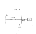
- Fig. 1 is an equivalent circuit of the system for explaining the principle of the present invention.
- a load power at the load end is designated as P + jQ
- V R designates load voltage
- V s voltage at the power source side.
- ⁇ is power factor angle of power source side impedance Z
- tan ⁇ X/R
- ⁇ is power factor angle of load side impedance Z L
- tan ⁇ X L /R L
- the short-circuit capacity S of the power system can be calculated from the above formula using the values of ⁇ , ⁇ and v R as the known value.
- power flow for stable voltage limit can be calculated and monitored by measuring the effective power P, reactive power Q and load side voltage V R at the load end and detecting changes of these values.
- VAR supply equipment When voltage tends to clip and a countermeasure is required after detection and discrimination of the current condition, VAR supply equipment is to be switched.
- improvement effect of the voltage stability limit value by the VAR supply equipment can be expressed as follows:
- v R a pair of values of v R can be obtained for w by solving the formula (1.11) for v R .
- the maximum power flow value w m can be proved in the following relationship by the calculation conducted below.
- the stability limit of power flow can be improved remarkably for the case where it is not inserted.
- the value of the stability limit improvement can also be foreseen because the values of Z, Y c , S, W, ⁇ , 0 can be known.
- Direction and magnitude of change for P, Q, V R can be known by supervising such values from time to time.
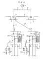
- Fig. 2, 2 and 3 designate the primary substations being connected to the power source 1 through the transmission lines 4, 5.
- the primary substations 2 and 3 are linked with the line 6.
- the primary substation 2 and secondary substation 11 are linked with the line 13 and the primary substation 2 and secondary substation 12, with the line 14.
- the load feeders 11 A, 11 B, 11 C, ... are connected to the low voltage side of bank 110 of the secondary substation. Moreover, it is also assumed that the tertiary side of bank 110 has VAR supply equipment on bus 15.
- the power flows from 1 to load through the transmission line 4, banks 10, 110 and feeders 11 A, 11 B, 11 C. Also from the bank 120 which is in parallel with the bank 110 of the secondary substation 11, the power flows to a load through the feeders 12A, 12B, 12C.
- control and monitoring device 17, 18 are respectively provided to the banks 110, 120 of the secondary substations 11, 12 on one to one. Since the feeders 11 A, 11B, 11 C, 12A, 12B, 12C viewed from the banks 110, 120 are all in the load area, the direction of the power flow is uniform.
- the power system seen upper from the control and monitoring device 17, 18 location can be regarded as the power source 1, and the feeders 11 A, 11 B, 12A, 12B, 12C as the load.
- the balance between the load and power source, and the variation of load are measured, detected and monitored around the banks 110, 120 and the VAR supply equipments 11 Z (shunt reactor 11 ZL, shunt capacitor 11 ZC) are adjusted and controlled as required.
- the system as an object of the present invention has the configuration and layout described above and the power flow of that system flows in uniform direction.
- the bus of load voltage V R described in the explanation about the principle corresponds to a high voltage bus of the secondary substations 11, 12, the banks 110, 120 and others to a load side and a part of the phase modifying equipments 11ZL, 11ZC, 12ZL, 12ZC connected to the buses 15, 16 of the phase modifying equipment to a shunt capacitor (SC).
- SC shunt capacitor
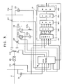
- 20 designates a primary circuit breaker of the bank 110; 21, potential transformer for high voltage bus; 22, current transformer for primary current of bank 110; 23, transformer for measuring voltage of intermediate voltage bus; 24, current transformer for secondary current of the bank 110.
- Outputs of these PTs and CTs are input to the on-load tap changing control panel 19 and the control and supervisory devices 17.
- 25 designates current transformer for tertiary current of the bank 110 and the output thereof is also input to the control and supervisory apparatus 17.
- 19 is existing on-load tap changer control panel (hereinafter referred to as LRA panel) having the voltage-reactive power regulating function.
- the control and supervisory devices 17 is provided for controlling such LRA panel 19.
- control and supervisory devices 17 will be explained hereunder in detail.
- converter circuit which receives four signals being input to the LRA panel 19 and the signal sent directly from the transformer for measuring tertiary current of the bank 110. With these inputs, the effective power P, reactive power Q, primary voltage V R of bank, secondary voltage of bank, tertiary capacitance Q c of bank of the bank 110 as a whole are measured.
- 183 denotes multiplexer which receives the five kinds of quantities of whole effective power P, reactive power Q, primary voltage V R of bank, secondary voltage of bank and tertiary capacitance of bank of the bank 110 from the output side of sample hold amplifier 182 and switches them over by the control command from the microcontroller 185.
- A/D converter connected to the multiplexer 183 for converting an input analog voltage into a digital value.
- microcontroller 185 designates microcontroller connected to the A/D converter 184. This microcontroller sequentially receives inputs of such analog measured value for the functional operation to be described hereafter, operating the circuit breakers 11 Z1, 11 Z2 through the LRA apparatus 19 with the result of such functional operation and also transmitting the result to the electrical stations for operating and controlling the primary side of the secondary substation.
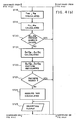
- Each rate of change of effective power P and reactive power Q is calculated from power flow (P,Q), load voltage V R and previously measured value of them and a phase angle 0 of system impedance is estimated in the step ST12 in accordance with the formula (1.2). Within a very short period, the phase angle ⁇ may be assumed as constant.
- the phase angle 0 of the load is measured in the step ST13.
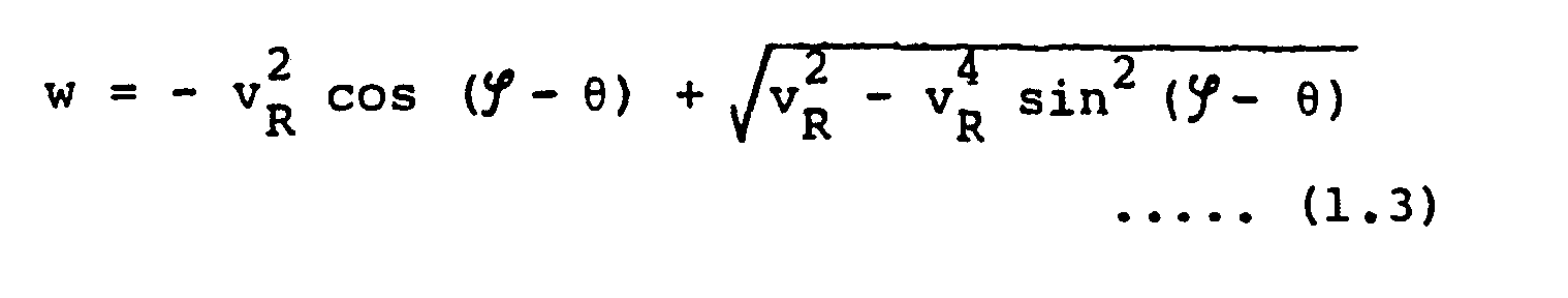
- the normalized power flow w is calculated by the formula (1.3) using the phase angle ⁇ of power source and the phase angle 0 of load.
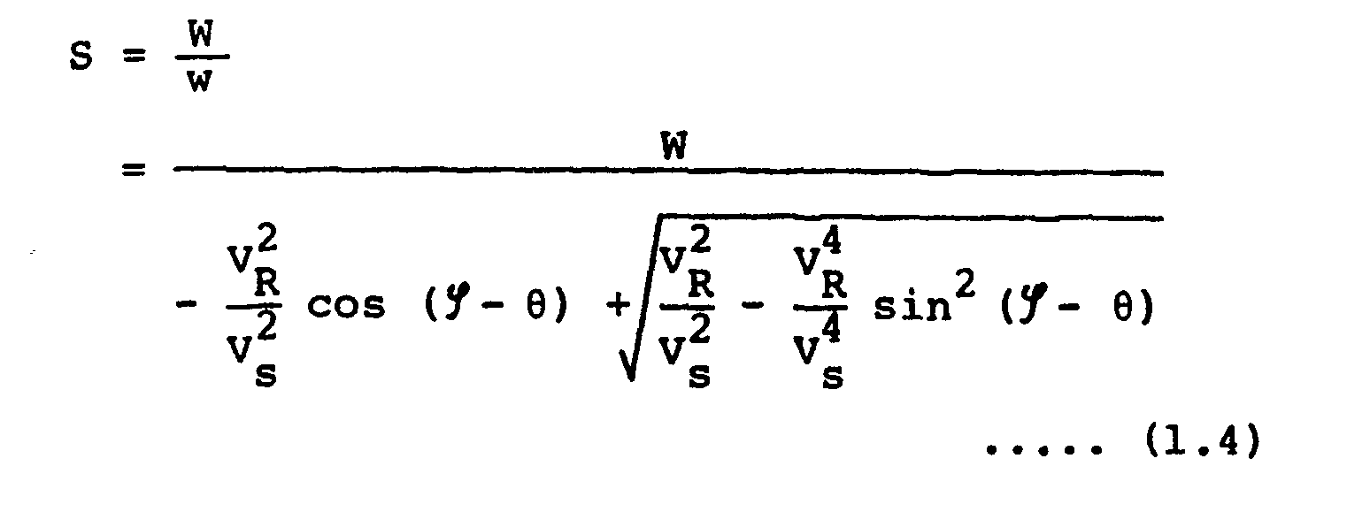
- the short-circuit capacity S of the system is obtained in the step ST14 by dividing a value of power flow W with the normalized power flow w.
- V R , P, Q, W, S, ⁇ , 0 are already known, following values can be obtained for the adequate time interval At in the step ST15 from such values.
- step ST17 sequential operation is shifted to the next step (step ST17) regarding such values to be within the area of the pattern of system dynamic change.
- the stability limit values of the system with constant power loads such as VRm , w m of the formulae (1.5), (1.6) are obtained in the step ST18 using the values of ⁇ , 0 (S, P, W, V R ) obtained from the assumption method described above.
- margin of power flow limit (formula 1.7) in the case where whole loads can be considered as the constant power load is obtained in the step ST19.
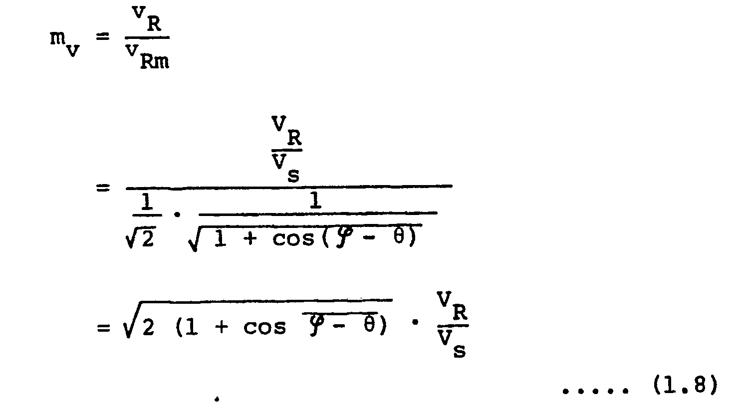
- a voltage margin m v for the voltage stability limit can be checked in the step ST20 using the formula (1.8).
- sensitivity coefficient of the power flow-voltage is again calculated using the formulae (1.9) and (1.10).
- This sensitivity coefficient becomes large with the increase of power flow, but it is also known that not only the sensitivity coefficient of q- VR but also the sensitivity coefficient of p-v R become large at the value near voltage stability limit as causing voltage to be fallen rapidly. Particularly when the values of ⁇ v R / ⁇ P, ⁇ vR/ ⁇ q exceed 1, it indicates that the system operation is in the dangerous area. Therefore, it is decided whether such values have exceeded or not the set value obtained by dividing such value with an adequate margin. When the value is in the safe zone, operation is continued, and otherwise, the system change operation starts (step ST22, 23).
- VAR supply equipment capacity which may be obtained at the adjusting point
- the required minimum equipment capacity is applied or when such value is larger, the maximum equipment capacity which may be available at present is applied (step ST25, 26).
- VAR supply equipment which may be operated is short in total, such information is transmitted to the electrical station which is capable of operating the systems of the wider range including such load system as the object of operation (step ST27), and, for example, possibility of similar voltage adjustment is decided for operation in the primary substation 2 shown in Fig. 2.
- step ST28 the value before adjusting operation is compared with current value.
- step ST30 a value being change of system condition generated by such turning on is used for deciding (step ST30) the short-circuit impedance Z and short-circuit capacity S.
- it is stored as values of the new system constants which is used for deciding the next sequential operation after this operation,
- step ST31 when improving effect of system operation is still insufficient, various values such as insufficient VAR supplying capacity and other system conditions are transmitted to the electrical stations of the higher voltage side, enabling the system operation viewed from the upper voltage side (step ST31).
Landscapes
- Engineering & Computer Science (AREA)
- Power Engineering (AREA)
- Supply And Distribution Of Alternating Current (AREA)
- Control Of Electrical Variables (AREA)
Abstract
Description
- The present invention relates to a voltage-reactive power control apparatus in corporated to reactive power supplying equipment for adequately sustaining load side voltages in the power system.
- A voltage of the power system always fluctuates, as is well known, in accordance with change of demand and supply. Large voltage fluctuation affects not only normal application or operation life of a variety of electrical appliances connected to the system, consumers but also insulation design of various power apparatus to be installed in the power system, and moreover results in interferes for stable and efficient operations of the system including a power generator from the viewpoint of operation of the power system. Namely, the voltage-reactive power control is essential for all electrical appliances and power apparatuses connected to the power system to ensure normal operations and for realizing stable and efficient operations of the system.
- Moreover, due to the increase in demand of power and difficulties in obtaining power plant site insufficiency of location caused by environmental problem, the recent power generation plant is in the situation as the far remoted and localized, realization of large scale power generation base through utilization of a large capacity generator unit and long distance and high voltage transmission and heavier power flow in the power transmission facilities.
- Of various problems to be overcome for safe and economical running of a higher density, larger capacity power system which is expanding and being more complicated from hear after year, followings are considered as the essential problems, although a voltage problem may not easily be evaluated directly from the economical viewpoint in its effect.
- (1) Voltage drop under a heavy load
- (2) Abnormal rise of voltage under light load
- (3) Voltage drop during system failure
- (4) Improvement in performance of voltage-reactive power control during system operation.
- The items (1), (2) will be described hereunder in more detail.
- In general, a voltage of power system is maintained and adjusted to a preset reference value through the voltage-reactive power control of the generator and phase modifying equipment. However, if the large supply power of VAR supply equipments falls a load increases suddenly or demand and supply of the reactive power is unbalanced, voltage of the primary system may abnormally fall or rise under the situation where the power system is grown-up in scale.
- Such a system operating situation is reported in detail in the Technical Report of Japan Electrical Engineering Society (Part II), No. 238, P60.
- However, such voltage fail or unstable phenomenon and is not eliminated. When a cause is once set up, a local and minor failure is first generated and it is then developed to the wider and major failure. Therefore, detection at early stage and quick counter-measures are required.
- Since the voltage-reactive power control apparatus of the prior art has mainly assigned monitoring and operation for such voltage variation or voltage abnormalities to the load dispatching center which manages operation of the whole system. Moreover the information coming from the load end is delayed, and synchronized informations are not obtained. Therefore these informations are inaccurate to be used.
- The present invention has been proposed to solve such problems and therefore it is an object of the present invention to provide a voltage-reactive power control apparatus which takes a measure for a local failure and then spreading the range for measure in case when wider area measure required.
- The voltage reactive-power adjusting equipment of the present invention is installed at the principal point of the load area in the power system.
- The equipment first detects the power flow into load and the voltage at the load side with the control and monitoring device within the equipment.
- Next the rate of change of the power-flow and that of the voltage are calculated from the measured value obtained as above. When each of the rate of change exceed their own limit value, the margin value calculated by the following system data to determine the control signal to VAR supply equipment with proper time delay, where the system data includes short circuit capacity of the power system, the power flow, the load-side voltage, and the voltage stability limit of the system calculated as assumed the load being constant-power load.
- Especially when the margin for the above rate-of-change of voltage is small, the control signal to the VAR supply equipment has time delay which depends on the ratio of voltage change to VAR supply change.
- The voltage-reactive power control apparatus of the present invention also forecasts voltage collapse by detecting voltage drop which is often generated in local load area of the system and quickly operates the near-by apparatus and besides sends informations to the upper level dispatching stations controlling the wider part of system. Moreover, if a countermeasure for wider range of system is required, the apparatus of the present invention takes the preventive control action which may be done properly for the wider area of system.
-
- Fig. 1 is an equivalent circuit of the system for explaining the principle which is the base of the present invention.
- Fig. 2 is a block diagram of the configuration of a voltage-reactive power control apparatus depending on a preferred embodiment of the present invention.
- Fig. 3 is a block diagram of the detailed configuration of a control and supervisory devices shown in Fig. 2.
- Fig. 4 is a flowchart of the operations of a voltage-reactive power control apparatus depending on the preferred embodiment of the present invention.
- A preferred embodiment of the present invention will be explained hereunder with reference to the accompanying drawings.
- First, the principle will be explained. Fig. 1 is an equivalent circuit of the system for explaining the principle of the present invention. In this figure, a load (power at the load end is designated as P + jQ) is connected to the system in the power source side through an impedance Z in the side of power source. VR designates load voltage and Vs, voltage at the power source side.
- With the short-circuit capacity of the system designated as S, following standardization can be carried out.


- Namely, when the reference value of Vs is predetermined, the short-circuit capacity S of the power system can be calculated from the above formula using the values of φ, θ and vR as the known value.
- In addition, it is known that the formula (1.1) shows the stable limit point when the load is constant power load, with the relationships as


- From this result, a surplus of the current load flow and voltage for the stable limit can be calculated by the following calculation.
- Namely,


- Finally the present margin of power flow and voltage for the stability limit can be monitored constantly by the calculations of formulae (1.7), (1.8).
- Finally, using a value S, values of p and q may be obtained as follow,


- In summary of the above, power flow for stable voltage limit, margin of active power flow and voltage for the stable limit and sensitivity coefficient of voltage for change of power flow can be calculated and monitored by measuring the effective power P, reactive power Q and load side voltage VR at the load end and detecting changes of these values.
- When voltage tends to clip and a countermeasure is required after detection and discrimination of the current condition, VAR supply equipment is to be switched.
- If it is supposed that the VAR supply equipments having admittance Yc is switched, following relationship can be obtained.

- This formula can be written as follows through comparison of absolute values in the right and left sides.


- This is similar to the formula (1.11).
- It is understood from the following explanation, load power in satisfying the above relationship becomes larger than the value in satisfying the formula (1.11) for the same load voltage VR.
- Namely, improvement effect of the voltage stability limit value by the VAR supply equipment can be expressed as follows:
- First from the formula (1.11)
- v


- + 2v

- When this formula is differentiated for w as indicated below.


- In case a shunt capacitor is inserted,

- Here, under the following preambles,


- The formula (1.12) can be solved for w.

- Moreover, the formula (1.14) can also be solved for w.

- Next, the sign of the second item in the radical sign of the second item in the formula (1.16) is checked.


- Comparison between the value in the radical sign of the second items of the formulae (1.14) and (1.15) results in the following relationship.

- =-sin2 (φ - θ) - (b2 -a2) + a2 sin2 (φ - θ)
- =-(b2-a2)-(1- a2) sin2 (φ - θ) < 0
- In the same way, comparison between the first items results in the following relationship.

Δ1 +Δ2<0
Therefore
w-w' =Δ1+Δ2<0∴w<w'

- On the contrary, a pair of values of vR can be obtained for w by solving the formula (1.11) for vR. In the case of inserting the shunt capacitor, the maximum power flow value wm can be proved in the following relationship by the calculation conducted below.

- Meanwhile, using the time reference adequately controlled, such stability limit can also be obtained from P, Q, VR obtained by measuring

- Direction and magnitude of change for P, Q, VR can be known by supervising such values from time to time.
- Namely, it can be determined whether values of p, q, v are changing suddenly or gradually and in the safe or risky direction by checking relationship of

- A system configuration indicating the embodiment of the present invention will then be explained.
- In Fig. 2, 2 and 3 designate the primary substations being connected to the
power source 1 through thetransmission lines primary substations line 6. - 11, 12 ... are the secondary substations located near the load areas from the primary substations. The
primary substation 2 andsecondary substation 11 are linked with theline 13 and theprimary substation 2 andsecondary substation 12, with theline 14. - The
load feeders 11 A, 11 B, 11 C, ... are connected to the low voltage side ofbank 110 of the secondary substation. Moreover, it is also assumed that the tertiary side ofbank 110 has VAR supply equipment onbus 15. - With such system configuration, the power flows from 1 to load through the
transmission line 4,banks feeders bank 110 of thesecondary substation 11, the power flows to a load through thefeeders 12A, 12B, 12C. - In such a power system, the control and
monitoring device banks 110, 120 of thesecondary substations feeders banks 110, 120 are all in the load area, the direction of the power flow is uniform. - That is, the power system seen upper from the control and
monitoring device power source 1, and thefeeders - Besides the reverse power flow does not occur.
- In such a system configuration and layout of apparatuses and devices, the balance between the load and power source, and the variation of load are measured, detected and monitored around the
banks 110, 120 and the VAR supply equipments 11 Z (shuntreactor 11 ZL,shunt capacitor 11 ZC) are adjusted and controlled as required. The system as an object of the present invention has the configuration and layout described above and the power flow of that system flows in uniform direction. - Namely, the bus of load voltage VR described in the explanation about the principle corresponds to a high voltage bus of the
secondary substations banks 110, 120 and others to a load side and a part of the phase modifying equipments 11ZL, 11ZC, 12ZL, 12ZC connected to thebuses - A practical example of the control and monitoring devices connected to the system will be explained.
- In Fig. 3, the same elements as that in Fig. 2 are given the like numerals and the same explanation will not be repeated.
- In that figure, 20 designates a primary circuit breaker of the
bank 110; 21, potential transformer for high voltage bus; 22, current transformer for primary current ofbank 110; 23, transformer for measuring voltage of intermediate voltage bus; 24, current transformer for secondary current of thebank 110. Outputs of these PTs and CTs are input to the on-load tap changingcontrol panel 19 and the control andsupervisory devices 17. 25 designates current transformer for tertiary current of thebank 110 and the output thereof is also input to the control andsupervisory apparatus 17. 19 is existing on-load tap changer control panel (hereinafter referred to as LRA panel) having the voltage-reactive power regulating function. The control andsupervisory devices 17 is provided for controllingsuch LRA panel 19. - Next, the control and
supervisory devices 17 will be explained hereunder in detail. - 181 denotes converter circuit which receives four signals being input to the
LRA panel 19 and the signal sent directly from the transformer for measuring tertiary current of thebank 110. With these inputs, the effective power P, reactive power Q, primary voltage VR of bank, secondary voltage of bank, tertiary capacitance Qc of bank of thebank 110 as a whole are measured. - 182 denotes sample and hold amplifier which holds analog value of output voltage of converting
circuit 181. - 183 denotes multiplexer which receives the five kinds of quantities of whole effective power P, reactive power Q, primary voltage VR of bank, secondary voltage of bank and tertiary capacitance of bank of the
bank 110 from the output side ofsample hold amplifier 182 and switches them over by the control command from themicrocontroller 185. - 184 denotes A/D converter connected to the
multiplexer 183 for converting an input analog voltage into a digital value. - 185 designates microcontroller connected to the A/
D converter 184. This microcontroller sequentially receives inputs of such analog measured value for the functional operation to be described hereafter, operating thecircuit breakers 11 Z1, 11 Z2 through theLRA apparatus 19 with the result of such functional operation and also transmitting the result to the electrical stations for operating and controlling the primary side of the secondary substation. - Next, operations of the control and
supervisory devices 17 will then be explained using a flowchart of Fig. 4. - First, a load voltage VR at the principal point in the system connecting the apparatus of the present invention and a power flow W (= P + jQ) flowing into the load passing through such point are read in the step ST11.
- Each rate of change of effective power P and reactive power Q is calculated from power flow (P,Q), load voltage VR and previously measured value of them and a phase angle 0 of system impedance is estimated in the step ST12 in accordance with the formula (1.2). Within a very short period, the phase angle φ may be assumed as constant. Next, the phase angle 0 of the load is measured in the step ST13. After obtaining the value of X/R, the normalized power flow w is calculated by the formula (1.3) using the phase angle φ of power source and the phase angle 0 of load. Next, the short-circuit capacity S of the system is obtained in the step ST14 by dividing a value of power flow W with the normalized power flow w.
- Here, since the values of VR, P, Q, W, S, φ, 0 are already known, following values can be obtained for the adequate time interval At in the step ST15 from such values.


- From the values of p, q, w, vR and the current values of p, q, w, VR, the variation and the rate of the change (magnitude and direction) of the power flow and voltage normalized in current can be sensed in the step ST16.
- When the power flow and voltage values observed in these case are near the reference limit value having been set by separate calculation on the off line basis, or in case the power flow and voltage are yet far from the reference limit value but these rates of the change are large, sequential operation is shifted to the next step (step ST17) regarding such values to be within the area of the pattern of system dynamic change.
- Namely, the stability limit values of the system with constant power loads such as VRm, wm of the formulae (1.5), (1.6) are obtained in the step ST18 using the values of ϕ, 0 (S, P, W, VR) obtained from the assumption method described above.
- Using these values, margin of power flow limit (formula 1.7) in the case where whole loads can be considered as the constant power load is obtained in the step ST19.

- A voltage margin mv for the voltage stability limit can be checked in the step ST20 using the formula (1.8).
- This value is recognized to be proper if the difference between this and the stability limit calculated separately by the off-line calculation is not significant. Then the power system operation can be safely continued (steps ST21 - 23).
- If this value is larger than a reference model value of the off-line calculation, sensitivity coefficient of the power flow-voltage is again calculated using the formulae (1.9) and (1.10).
- This sensitivity coefficient becomes large with the increase of power flow, but it is also known that not only the sensitivity coefficient of q-VR but also the sensitivity coefficient of p-vR become large at the value near voltage stability limit as causing voltage to be fallen rapidly. Particularly when the values of δvR/δP, δvR/δq exceed 1, it indicates that the system operation is in the dangerous area. Therefore, it is decided whether such values have exceeded or not the set value obtained by dividing such value with an adequate margin. When the value is in the safe zone, operation is continued, and otherwise, the system change operation starts (step ST22, 23).
- For the change of the system operation, switching of VAR supply equipment is required. The required amount of VAR to be supplied from the equipment is calculated from the equation (1.11) giving the system voltage VR to be maintained for the present power flow.
- When a calculated VAR value is within VAR supply equipment capacity which may be obtained at the adjusting point, the required minimum equipment capacity is applied or when such value is larger, the maximum equipment capacity which may be available at present is applied (step ST25, 26).
- If the VAR supply equipment which may be operated is short in total, such information is transmitted to the electrical station which is capable of operating the systems of the wider range including such load system as the object of operation (step ST27), and, for example, possibility of similar voltage adjustment is decided for operation in the
primary substation 2 shown in Fig. 2. - After a series of such operations proceeded and the VAR supply equipment is operated (or in some cases, that equipment is turned off), changes occur for the voltage -power flow of the system. Therefore, such changes are detected and measured in the step ST28. In the step ST29 the value before adjusting operation is compared with current value. Thereby, verifying the improved effect of system (voltage - power flow) operation.
- In case such effect is considered sufficient, a value being change of system condition generated by such turning on is used for deciding (step ST30) the short-circuit impedance Z and short-circuit capacity S. At the same time, it is stored as values of the new system constants which is used for deciding the next sequential operation after this operation,
- In addition, when improving effect of system operation is still insufficient, various values such as insufficient VAR supplying capacity and other system conditions are transmitted to the electrical stations of the higher voltage side, enabling the system operation viewed from the upper voltage side (step ST31).
Claims (5)
Priority Applications (4)
| Application Number | Priority Date | Filing Date | Title |
|---|---|---|---|
| JP62234970A JPH0734624B2 (en) | 1987-09-21 | 1987-09-21 | Voltage-reactive power controller |
| US07/323,879 US4916377A (en) | 1987-09-21 | 1989-03-15 | Voltage-reactive power control apparatus |
| DE68925196T DE68925196T2 (en) | 1987-09-21 | 1989-03-18 | Reactive power control device |
| EP89104914A EP0388479B1 (en) | 1987-09-21 | 1989-03-18 | Voltage-reactive power control apparatus |
Applications Claiming Priority (3)
| Application Number | Priority Date | Filing Date | Title |
|---|---|---|---|
| JP62234970A JPH0734624B2 (en) | 1987-09-21 | 1987-09-21 | Voltage-reactive power controller |
| US07/323,879 US4916377A (en) | 1987-09-21 | 1989-03-15 | Voltage-reactive power control apparatus |
| EP89104914A EP0388479B1 (en) | 1987-09-21 | 1989-03-18 | Voltage-reactive power control apparatus |
Publications (2)
| Publication Number | Publication Date |
|---|---|
| EP0388479A1 true EP0388479A1 (en) | 1990-09-26 |
| EP0388479B1 EP0388479B1 (en) | 1995-12-20 |
Family
ID=55357646
Family Applications (1)
| Application Number | Title | Priority Date | Filing Date |
|---|---|---|---|
| EP89104914A Expired - Lifetime EP0388479B1 (en) | 1987-09-21 | 1989-03-18 | Voltage-reactive power control apparatus |
Country Status (4)
| Country | Link |
|---|---|
| US (1) | US4916377A (en) |
| EP (1) | EP0388479B1 (en) |
| JP (1) | JPH0734624B2 (en) |
| DE (1) | DE68925196T2 (en) |
Cited By (1)
| Publication number | Priority date | Publication date | Assignee | Title |
|---|---|---|---|---|
| CN109031000A (en) * | 2018-08-03 | 2018-12-18 | 贵州电网有限责任公司电网规划研究中心 | A kind of method and system based on non-faulting disturbance In situ Measurement grid short circuit capacity |
Families Citing this family (28)
| Publication number | Priority date | Publication date | Assignee | Title |
|---|---|---|---|---|
| US5081591A (en) * | 1990-02-28 | 1992-01-14 | Westinghouse Electric Corp. | Optimizing reactive power distribution in an industrial power network |
| CA2050068A1 (en) * | 1990-09-27 | 1992-03-28 | Richard Wayne Glaser | Power factor improving arrangement |
| WO1993020497A1 (en) * | 1992-04-01 | 1993-10-14 | Pennsylvania Power & Light Company | Control system and method for the parallel operation of voltage regulators |
| EP0757855A1 (en) * | 1994-04-29 | 1997-02-12 | Michigan State University | Method for performing a voltage stability security assessment for a power transmission system |
| JPH09512699A (en) * | 1994-04-29 | 1997-12-16 | ミシガン ステイト ユニヴァーシティー | How to improve the certainty of voltage stability of a transmission system |
| DE19528827C1 (en) * | 1995-08-05 | 1996-12-12 | Reinhausen Maschf Scheubeck | Control of transformer tap or stepping switches e.g. for power supply installation |
| SE506199C2 (en) * | 1996-03-26 | 1997-11-17 | Asea Brown Boveri | Method and apparatus for determining the short-circuit power of an AC power network connected to a high-voltage direct current transmission |
| DE19731860C1 (en) * | 1997-07-24 | 1999-01-28 | Freudenberg Carl Fa | Dust filter bag |
| US6121758A (en) * | 1999-06-23 | 2000-09-19 | Daq Electronics, Inc. | Adaptive synchronous capacitor switch controller |
| ES2449386T3 (en) * | 2007-12-28 | 2014-03-19 | Vestas Wind Systems A/S | Procedure to control a mains voltage |
| US8588993B2 (en) * | 2008-11-05 | 2013-11-19 | Abb Research Ltd. | Voltage regulation optimization |
| CN102308451B (en) * | 2009-02-05 | 2014-11-05 | Abb研究有限公司 | Integrated voltage and var optimization process for a distribution system |
| JP5618758B2 (en) * | 2010-10-18 | 2014-11-05 | 株式会社東芝 | Method and system for monitoring short-circuit capacity of power system |
| CN102074964B (en) * | 2011-01-26 | 2014-07-23 | 中国电力科学研究院 | A fast analysis method for power system reactive power balance and critical power flow |
| US8922175B2 (en) | 2011-03-31 | 2014-12-30 | General Electric Company | System and method for operating capacitor banks |
| US9570909B2 (en) | 2011-07-26 | 2017-02-14 | General Electric Company | Devices and methods for decentralized power loss reduction control |
| US8965588B2 (en) | 2011-07-26 | 2015-02-24 | General Electric Company | Devices and methods for decentralized voltage control |
| US8761954B2 (en) | 2011-07-26 | 2014-06-24 | General Electric Company | Devices and methods for decentralized coordinated volt/VAR control |
| US8838284B2 (en) | 2011-07-26 | 2014-09-16 | General Electric Company | Devices and methods for decentralized Volt/VAR control |
| US8838285B2 (en) | 2011-07-26 | 2014-09-16 | General Electric Company | Devices and methods for decentralized power factor control |
| US9104184B2 (en) * | 2011-09-16 | 2015-08-11 | Varentec, Inc. | Systems and methods for switch-controlled VAR sources coupled to a power grid |
| JP5893544B2 (en) * | 2011-10-31 | 2016-03-23 | パナソニック株式会社 | Voltage control device, voltage control method, power adjustment device, and voltage control program |
| US9590423B2 (en) | 2012-08-31 | 2017-03-07 | Abb Research Ltd. | Power distribution system loss reduction with distributed energy resource control |
| CN103219730B (en) * | 2013-03-14 | 2014-12-17 | 武汉大学 | Estimation method of capacity exchange ability between large regional grids of electric system |
| DE102013210812A1 (en) * | 2013-06-10 | 2014-12-11 | Wobben Properties Gmbh | Method for feeding electrical power into an electrical supply network |
| US9997921B2 (en) | 2015-10-07 | 2018-06-12 | General Electric Company | Solar power conversion system and method |
| US9847647B2 (en) | 2015-10-07 | 2017-12-19 | General Electric Company | Solar power conversion system and method |
| CN110326182B (en) | 2015-11-09 | 2023-11-24 | 日立能源有限公司 | Hierarchical robust model predictive voltage and VAR control with coordination and optimization of autonomous DER voltage control |
Citations (1)
| Publication number | Priority date | Publication date | Assignee | Title |
|---|---|---|---|---|
| EP0260504A2 (en) * | 1986-09-09 | 1988-03-23 | Kabushiki Kaisha Toshiba | Reactive power compensation circuit |
Family Cites Families (4)
| Publication number | Priority date | Publication date | Assignee | Title |
|---|---|---|---|---|
| CH556105A (en) * | 1973-03-14 | 1974-11-15 | Bbc Brown Boveri & Cie | ADJUSTABLE REACTIVE POWER COMPENSATOR ON AN ELECTRICAL SINGLE- OR MULTI-PHASE TRANSMISSION NETWORK AND METHOD FOR OPERATING THE COMPENSATOR. |
| DE2644682A1 (en) * | 1976-10-02 | 1978-04-06 | Bbc Brown Boveri & Cie | CIRCUIT ARRANGEMENT AND METHOD FOR COMPENSATION AND SYMMETRATION OF RAPIDLY CHANGEABLE BLIND CURRENTS FROM CONSUMERS CONNECTED TO A THREE-PHASE POWER SUPPLY |
| US4121150A (en) * | 1977-07-25 | 1978-10-17 | General Electric Company | Gain compensation for power factor in line current regulating systems involving reactive power |
| US4677364A (en) * | 1985-01-04 | 1987-06-30 | The United States Of America As Represented By The United States Department Of Energy | Reactive power compensating system |
-
1987
- 1987-09-21 JP JP62234970A patent/JPH0734624B2/en not_active Expired - Fee Related
-
1989
- 1989-03-15 US US07/323,879 patent/US4916377A/en not_active Expired - Lifetime
- 1989-03-18 DE DE68925196T patent/DE68925196T2/en not_active Expired - Fee Related
- 1989-03-18 EP EP89104914A patent/EP0388479B1/en not_active Expired - Lifetime
Patent Citations (1)
| Publication number | Priority date | Publication date | Assignee | Title |
|---|---|---|---|---|
| EP0260504A2 (en) * | 1986-09-09 | 1988-03-23 | Kabushiki Kaisha Toshiba | Reactive power compensation circuit |
Non-Patent Citations (2)
| Title |
|---|
| IEEE TRANSACTIONS ON INDUSTRY APPLICATIONS, vol. IA-22, no. 6, November/December 1986, pages 1091-1104, IEEE, New York, NY, US; L.H. WALKER: "Force-commutated reactive-power compensator" * |
| REV. GENER. DE L'ELECTR., vol. 88, no. 1, January 1979, pages 58-72; M. BOIDIN et al.: "Performances dynamiques des compensateurs statiques à thyristors et principes de régulation" * |
Cited By (2)
| Publication number | Priority date | Publication date | Assignee | Title |
|---|---|---|---|---|
| CN109031000A (en) * | 2018-08-03 | 2018-12-18 | 贵州电网有限责任公司电网规划研究中心 | A kind of method and system based on non-faulting disturbance In situ Measurement grid short circuit capacity |
| CN109031000B (en) * | 2018-08-03 | 2019-08-16 | 贵州电网有限责任公司电网规划研究中心 | A method and system for on-site measurement of short-circuit capacity of power grid based on non-fault disturbance |
Also Published As
| Publication number | Publication date |
|---|---|
| DE68925196T2 (en) | 1996-09-05 |
| DE68925196D1 (en) | 1996-02-01 |
| EP0388479B1 (en) | 1995-12-20 |
| US4916377A (en) | 1990-04-10 |
| JPS6481623A (en) | 1989-03-27 |
| JPH0734624B2 (en) | 1995-04-12 |
Similar Documents
| Publication | Publication Date | Title |
|---|---|---|
| EP0388479A1 (en) | Voltage-reactive power control apparatus | |
| US6219591B1 (en) | Voltage instability predictor (VIP)—method and system for performing adaptive control to improve voltage stability in power systems | |
| US10998756B2 (en) | Microgrid system and method for managing malfunction | |
| JP4610762B2 (en) | Method and apparatus for assessing the stability of a power transmission network | |
| CA2359322C (en) | Electric utility system with superconducting magnetic energy storage | |
| US8775104B2 (en) | Method and system for protecting an electrical power transmission network | |
| US10027121B2 (en) | Method and apparatus for controlling stability of a local power grid | |
| CA1186729A (en) | Control system for dc power transmission | |
| KR100333090B1 (en) | Apparatus and method for compensating power quality of power distribution line | |
| CN116982232B (en) | Control method, computer program product, control system and use | |
| Castro et al. | „Co-ordination of parallel AC-DC systems for optimum performance | |
| Yunus et al. | A combined zone-3 relay blocking and sensitivity-based load shedding for voltage collapse prevention | |
| Force | Var management-problem recognition and control | |
| RU225949U1 (en) | DEVICE FOR REGULATING THE STATIC REACTIVE POWER COMPENSATOR AT THE CONTACT NETWORK SECTIONATION POST | |
| JPH04275029A (en) | Load interrupting device at time of parallel off fault | |
| JPS60241726A (en) | Power system control system | |
| Venikov et al. | General philosophy of emergency control in the UPG of the USSR | |
| JPS6192126A (en) | Power system stabilizer | |
| JPH0581926B2 (en) | ||
| Boyko et al. | Integration of a static var system into Fargo substation | |
| Arai et al. | Design and operation of SVC for voltage support at Mussafah substation in Abu Dhabi | |
| Karnasuta et al. | Security Control of Small Longitudinal Systems | |
| JPH0734625B2 (en) | Voltage / reactive power control | |
| Kennedy | Transmission loadability—Some protection applications | |
| Wehenkel | Analysis of electric power and energy systems |
Legal Events
| Date | Code | Title | Description |
|---|---|---|---|
| PUAI | Public reference made under article 153(3) epc to a published international application that has entered the european phase |
Free format text: ORIGINAL CODE: 0009012 |
|
| AK | Designated contracting states |
Kind code of ref document: A1 Designated state(s): CH DE GB LI SE |
|
| 17P | Request for examination filed |
Effective date: 19900823 |
|
| 17Q | First examination report despatched |
Effective date: 19920423 |
|
| GRAA | (expected) grant |
Free format text: ORIGINAL CODE: 0009210 |
|
| AK | Designated contracting states |
Kind code of ref document: B1 Designated state(s): CH DE GB LI SE |
|
| REF | Corresponds to: |
Ref document number: 68925196 Country of ref document: DE Date of ref document: 19960201 |
|
| REG | Reference to a national code |
Ref country code: CH Ref legal event code: NV Representative=s name: WILLIAM BLANC & CIE CONSEILS EN PROPRIETE INDUSTRI |
|
| PLBE | No opposition filed within time limit |
Free format text: ORIGINAL CODE: 0009261 |
|
| STAA | Information on the status of an ep patent application or granted ep patent |
Free format text: STATUS: NO OPPOSITION FILED WITHIN TIME LIMIT |
|
| 26N | No opposition filed | ||
| REG | Reference to a national code |
Ref country code: GB Ref legal event code: IF02 |
|
| PGFP | Annual fee paid to national office [announced via postgrant information from national office to epo] |
Ref country code: SE Payment date: 20070307 Year of fee payment: 19 |
|
| PGFP | Annual fee paid to national office [announced via postgrant information from national office to epo] |
Ref country code: CH Payment date: 20070314 Year of fee payment: 19 Ref country code: GB Payment date: 20070314 Year of fee payment: 19 |
|
| PGFP | Annual fee paid to national office [announced via postgrant information from national office to epo] |
Ref country code: DE Payment date: 20070315 Year of fee payment: 19 |
|
| REG | Reference to a national code |
Ref country code: CH Ref legal event code: PL |
|
| EUG | Se: european patent has lapsed | ||
| GBPC | Gb: european patent ceased through non-payment of renewal fee |
Effective date: 20080318 |
|
| PG25 | Lapsed in a contracting state [announced via postgrant information from national office to epo] |
Ref country code: CH Free format text: LAPSE BECAUSE OF NON-PAYMENT OF DUE FEES Effective date: 20080331 Ref country code: LI Free format text: LAPSE BECAUSE OF NON-PAYMENT OF DUE FEES Effective date: 20080331 Ref country code: DE Free format text: LAPSE BECAUSE OF NON-PAYMENT OF DUE FEES Effective date: 20081001 Ref country code: SE Free format text: LAPSE BECAUSE OF NON-PAYMENT OF DUE FEES Effective date: 20080319 |
|
| PG25 | Lapsed in a contracting state [announced via postgrant information from national office to epo] |
Ref country code: GB Free format text: LAPSE BECAUSE OF NON-PAYMENT OF DUE FEES Effective date: 20080318 |