EP0388404B1 - Evaluation of a fluctuating variable - Google Patents
Evaluation of a fluctuating variable Download PDFInfo
- Publication number
- EP0388404B1 EP0388404B1 EP88905795A EP88905795A EP0388404B1 EP 0388404 B1 EP0388404 B1 EP 0388404B1 EP 88905795 A EP88905795 A EP 88905795A EP 88905795 A EP88905795 A EP 88905795A EP 0388404 B1 EP0388404 B1 EP 0388404B1
- Authority
- EP
- European Patent Office
- Prior art keywords
- average
- engine
- averages
- variable
- speed
- Prior art date
- Legal status (The legal status is an assumption and is not a legal conclusion. Google has not performed a legal analysis and makes no representation as to the accuracy of the status listed.)
- Expired - Lifetime
Links
Images
Classifications
-
- G—PHYSICS
- G01—MEASURING; TESTING
- G01P—MEASURING LINEAR OR ANGULAR SPEED, ACCELERATION, DECELERATION, OR SHOCK; INDICATING PRESENCE, ABSENCE, OR DIRECTION, OF MOVEMENT
- G01P11/00—Measuring average value of speed
-
- F—MECHANICAL ENGINEERING; LIGHTING; HEATING; WEAPONS; BLASTING
- F02—COMBUSTION ENGINES; HOT-GAS OR COMBUSTION-PRODUCT ENGINE PLANTS
- F02B—INTERNAL-COMBUSTION PISTON ENGINES; COMBUSTION ENGINES IN GENERAL
- F02B3/00—Engines characterised by air compression and subsequent fuel addition
- F02B3/06—Engines characterised by air compression and subsequent fuel addition with compression ignition
Abstract
Description
- The invention relates to a method of evaluating a fluctuating variable, particularly the speed of a diesel engine having electronic diesel control, in accordance with the pre-characterizing clause of claim 1. The invention also relates to a device for evaluating a fluctuating variable, particularly engine speed (n) for the electronic control of a diesel engine, in accordance with the pre-characterizing clause of claim 3.
- In the speed evaluation in an electronic diesel control (EDC) for diesel engines, it is known to use the so-called "segment" method in which engine speed is calculated by measuring the time interval between the passing of two successive marks (reference marks) on the engine crankshaft, these marks being equally angularly spaced. Four marks are provided for a four cylinder engine. During idling, the engine speed tends to fluctuate widely at a relatively low frequency, e.g. 5Hz, due to the resilient mounting of the engine on the vehicle body or chassis. It is an object of the EDC to damp or suppress these low frequency speed fluctuations but superimposed on these low frequency fluctuations is a higher frequency fluctuation, e.g. 25Hz for a four stroke four cylinder engine rotating at 750 r.p.m. This is due to the fluctuating torque produced by the combustion pressures developed in the individual engine cylinders. Using the known method, the output speed signals are almost in phase with the perfect 5Hz waveform from which the 25Hz frequency has been eliminated. However, the output speed signals still possesses the 25Hz component which is disadvantageous for the EDC, inasmuch as it is impossible for the EDC to compensate for the speed fluctuations due to the individual momentary combustion pressures. The 25Hz component can be effectively eliminated by taking averages of the input speed signals but this leads to a phase delay between the perfect 5Hz waveform and the output waveform, because the average pertaining to one reference mark cannot be calculated until a subsequent reference mark has passed.
- EP-A-0 133 426 describes a method of obtaining an average value of an almost periodically fluctuating signal, such as the angular velocity of the crankshaft of a diesel engine. To obtain a tone average, it is necessary to take the coverage, such as a running average, over one or several complete periods of fluctuation. However, when the engine speed changes suddenly, a corresponding change is not reflected in a corresponding sudden change in the average value as taken but only in a gradual change. To avoid this, EP-A-0 133 426 proposes to store the angular velocity signal at discrete points and to process the stored signal values later, e.g., by comparing the stored signal values with later actual signal values. Such comparison, in the event of a change in engine speed, results in a transient deviation. A running average is also taken of the fluctuating signal representing the angular velocity of the crankshaft and any transient deviation is added to this running average to obtain an output value which accurately represents the average engine speed at any given time. Disadvantages of the method of EP-A-0 133 426 are that it requires a large storage capacity and maybe additional memory components, special measures, with resulting expense, must be taken to ensure that the stored angular velocity values and the actual values with which they are compared are in synchronism with one another, requiring additional components, and the comparison of the stored and actual values representing the course of the fluctuating signal demands large computer capacity and the large computation times offset the advantage of the method in that a rapid engine speed response is obtained.
- These disadvantages are avoided by the method according to the characterizing clause of claim 1 and by the device according to the characterizing clause of claim 3. The extrapolation of averages virtually eliminates the phase delay between the output and input in the case of the low frequency fluctuations and the higher frequency fluctuations are almost absent from the output.
- A linear extrapolation from two successive averages of three successive input signals in accordance with
claims 2,4 and 5 is very simple to carry out and involves a minimum of extra components. - The invention is further described, by way of example, with reference to the accompanying drawings which relate to a four stroke, four cylinder diesel engine with EDC and in which:-
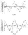
- Fig. 1 is a graph of instantaneous engine speed plotted against time for idling at 750 r.p.m;
- Fig. 2 is a comparable graph in which the higher frequency fluctuations have been eliminated in an idealized situation and showing the output obtained using the method and device of the invention;
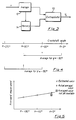
- Fig. 3 is a block diagram of a device according to the invention for evaluating a fluctuating engine speed;
- Fig. 4 is a timing diagram to illustrate the calculation of averages in the preferred embodiment; and
- Fig. 5 is a graph showing the extrapolation of the averages in accordance with the invention.
- The engine of a motor vehicle is part of an oscillatory system due to the resilient mounting of the engine, the natural frequency of such system during idling being, for example, 5Hz as assumed in Fig. 1. Thus, in the case of a diesel engine having EDC, there tends to be a positive speed signal feedback if there is any appreciable delay between the feedback signal and the instantaneous speed, resulting in fluctuations of the governed engine speed between wide limits; between 500 r.p.m. and 1000 r.p.m. in Fig. 1. However, superimposed on this low frequency fluctuation is a higher frequency fluctuation due to the momentary nature of the combustion pressures in the individual engine cylinders. In the case of a four stroke, four cylinder diesel engine rotating at 750 r.p.m, the frequency of such fluctuations is 25Hz and this is shown in Fig. 1 superimposed on the lower 5Hz frequency fluctuations.
- The higher frequency fluctuations, in practice are impossible to eliminate, but the input speed signals n derived from four equi-angularly spaced reference marks BM on the engine crankshaft can be processed to remove the higher frequency fluctuations which could adversely affect the EDC. This can be done simply by taking averages but such results in a substantial phase delay between the input speed signal n and the output signal Un and the EDC is then unable to suppress the lower frequency oscillation.
- Fig. 2 shows in full line a basic speed fluctuation which has been idealized into a perfect waveform of 5Hz by the smoothing of the 25Hz fluctuations. Fig. 2 shows in dotted lines the output signal Un obtained by the method and device of the invention from the input speed n shown in Fig. 1. It can be seen that the phase delay is very small, yet the 25Hz ripple has disappeared.
- This is achieved as shown in Fig. 3 by connecting an
extrapolating circuit 10 to acomponent 12 for calculating averages to amemory 14 for storing the immediately previously calculated average. Fig. 4 shows the two average speed values from which an average value pertaining to a crankshaft angle α =0° is estimated by extrapolation. The average speed value calculated at α =0° is calculated from the time at α =-180°, to the time at α =0° and is the average for α =-90°. The immediately preceding average speed value is calculated from the time at α =-90°, to the time at α =-270° and is the average for α =-180°. These two speed values are used to estimate the average for α =0°. This is shown in Fig. 5, wherein a straight line is drawn through the averaged instantaneous speeds for α =-180° and α=-90° to obtain an estimated averaged speed for α =0°. The actual averaged speed for α =0° is also indicated but this cannot be deduced until the instant at which α =+90°. This close approximation between the estimated fluctuations and the perfected fluctuations is illustrated in Fig. 2.
Claims (5)
- Method of evaluating a periodically fluctuating variable of an engine, having electronic control, particularly the speed (n) of a diesel engine, having electronic diesel control, by calculating in the electronic control a fixed number of averages of previously measured values of that variable, characterized in that the averages are determined for measuring intervals defined by predetermined, equally spaced angular positions of the crankshaft of the engine, and in that the actual averaged value of the variable is estimated by extrapolation from at least the last two averages calculated from the last preceding intervals.
- Method according to claim 1, characterized in that the extrapolation is linear.
- Device for evaluating a periodically fluctuating variable of a engine having electronic control, particularly the speed (n) of a diesel engine for the electronic diesel control, having a component (12) for calculating averages of that variable (n) and a memory (14) for storing at least one previously calculated average, characterized in that said extrapolating circuit (10) contains means for calculating said averages for intervals defined by predetetermined, equally spaced angular positions of the crankshaft and in that an extrapolating circuit (10) is provided for estimating the actual average value of the variable by extrapolation from the average just calculated by the calculating component (12) and the average or averages stored in the memory (14).
- Device according to claim 3, characterized in that the calculating component (12) calculates each average over the time interval during which the crankshaft rotates through an angle of 720° divided by the number of engine cylinders.
- Device according to claim 3 or 4, characterized in that the memory (14) stores the immediately preceding calculated average and the extrapolating circuit (10) extrapolates linearly from the just calculated average and the last stored average.
Applications Claiming Priority (1)
| Application Number | Priority Date | Filing Date | Title |
|---|---|---|---|
| PCT/EP1988/000584 WO1990000253A1 (en) | 1988-07-01 | 1988-07-01 | Evaluation of a fluctuating variable |
Publications (2)
| Publication Number | Publication Date |
|---|---|
| EP0388404A1 EP0388404A1 (en) | 1990-09-26 |
| EP0388404B1 true EP0388404B1 (en) | 1993-03-24 |
Family
ID=8165297
Family Applications (1)
| Application Number | Title | Priority Date | Filing Date |
|---|---|---|---|
| EP88905795A Expired - Lifetime EP0388404B1 (en) | 1988-07-01 | 1988-07-01 | Evaluation of a fluctuating variable |
Country Status (4)
| Country | Link |
|---|---|
| US (1) | US5040412A (en) |
| EP (1) | EP0388404B1 (en) |
| DE (1) | DE3879713T2 (en) |
| WO (1) | WO1990000253A1 (en) |
Families Citing this family (10)
| Publication number | Priority date | Publication date | Assignee | Title |
|---|---|---|---|---|
| DE3917978C2 (en) * | 1989-06-02 | 1998-04-02 | Bosch Gmbh Robert | Method for measuring rough running in an internal combustion engine, and use of the methods for detecting misfires |
| US5132909A (en) * | 1990-07-30 | 1992-07-21 | Saturn Corporation | Apparatus for diagnosing individual cylinder performance by estimated instantaneous engine speeds |
| US5623376A (en) * | 1991-04-03 | 1997-04-22 | Canon Kabushiki Kaisha | Digital information restoring device including period detector |
| US5311771A (en) * | 1992-03-30 | 1994-05-17 | Caterpillar Inc. | Method for determining the rotational position of a crankshaft of an internal combustion engine |
| US5361629A (en) * | 1992-08-21 | 1994-11-08 | Chrysler Corporation | Single sensor misfire detection apparatus and method for an internal combustion engine |
| JPH07259631A (en) * | 1994-03-18 | 1995-10-09 | Mitsubishi Electric Corp | Misfire detecting device of internal combustion engine |
| JP3441812B2 (en) * | 1994-09-08 | 2003-09-02 | 本田技研工業株式会社 | Device for detecting combustion state of internal combustion engine |
| US6216062B1 (en) * | 1999-11-11 | 2001-04-10 | Visteon Global Technologies, Inc. | Step-less vehicle display allowing irregular update intervals |
| DE10308000A1 (en) * | 2003-02-25 | 2004-09-02 | Volkswagen Ag | Control method for a motor vehicle electronic fuel injection system extrapolates a crank angle's time progression into the future to deduce control signals for triggering injection valves |
| DE102010009648A1 (en) * | 2010-02-27 | 2011-09-01 | Robert Bosch Gmbh | Method for determining a rotational speed of a drive shaft of an internal combustion engine |
Family Cites Families (4)
| Publication number | Priority date | Publication date | Assignee | Title |
|---|---|---|---|---|
| DE2616972B2 (en) * | 1976-04-17 | 1979-01-11 | Wabco Westinghouse Gmbh, 3000 Hannover | Method and circuit arrangement for digitally measuring the period of a rotating component, for example a vehicle wheel |
| US4281388A (en) * | 1979-07-09 | 1981-07-28 | Deere & Company | Tachometer |
| EP0133426B1 (en) * | 1983-07-20 | 1989-03-01 | VOEST-ALPINE AUTOMOTIVE Gesellschaft m.b.H. | Method for the rapid control of an average value, especially the arithmetic average of an almost periodic signal |
| US4779213A (en) * | 1987-05-27 | 1988-10-18 | Chrysler Motors Corporation | Electronic digital speedometer for a multi-measurand data communication system |
-
1988
- 1988-07-01 US US07/460,941 patent/US5040412A/en not_active Expired - Fee Related
- 1988-07-01 WO PCT/EP1988/000584 patent/WO1990000253A1/en active IP Right Grant
- 1988-07-01 EP EP88905795A patent/EP0388404B1/en not_active Expired - Lifetime
- 1988-07-01 DE DE8888905795T patent/DE3879713T2/en not_active Expired - Lifetime
Also Published As
| Publication number | Publication date |
|---|---|
| DE3879713T2 (en) | 1993-08-19 |
| EP0388404A1 (en) | 1990-09-26 |
| US5040412A (en) | 1991-08-20 |
| WO1990000253A1 (en) | 1990-01-11 |
| DE3879713D1 (en) | 1993-04-29 |
Similar Documents
| Publication | Publication Date | Title |
|---|---|---|
| EP0388404B1 (en) | Evaluation of a fluctuating variable | |
| US4744244A (en) | Cylinder pressure sensor output compensation method for internal combustion engine | |
| US4928652A (en) | Engine control system for suppressing car body vibration | |
| US7047122B2 (en) | Extrapolation method for the angle-of-rotation position | |
| US5021960A (en) | Combustion fault detection apparatus and control system for internal combustion engine | |
| EP0403212B1 (en) | Engine control system | |
| US20040236496A1 (en) | Method to determine tdc in an internal combustion engine | |
| GB2134265A (en) | Generating rotational speed data for an internal combustion engine | |
| US5386810A (en) | System and method for controlling a solenoid-valve-controlled fuel-metering device, particularly for a diesel gasoline engine | |
| US4635201A (en) | Apparatus for detecting amount of change in rotational speed of internal combustion engine | |
| US5050554A (en) | Ignition timing control apparatus for engines | |
| US4527422A (en) | Apparatus for determining the value of a cyclically varying parameter of an internal combustion engine | |
| GB2218828A (en) | Fuel injection control system for an automotive engine | |
| JPH08105781A (en) | Measurement-error correcting method | |
| US4548180A (en) | Method for controlling the operating condition of an internal combustion engine | |
| JPH02227532A (en) | Fuel injection control device | |
| JP3469254B2 (en) | Electronic fuel supply control device for internal combustion engine | |
| US4366792A (en) | Angle of advance correction signal generator | |
| US5566657A (en) | Acceleration responsive control system and method for internal combustion engine | |
| JP2726074B2 (en) | Method and apparatus for evaluating fluctuating variables | |
| JP2763294B2 (en) | Input signal detection device for internal combustion engine controller | |
| US4552110A (en) | Electronic ignition control system | |
| GB2374150A (en) | Method of Determining Engine Speed | |
| JPH0452382B2 (en) | ||
| JPS61116051A (en) | Method for processing engine control signal |
Legal Events
| Date | Code | Title | Description |
|---|---|---|---|
| PUAI | Public reference made under article 153(3) epc to a published international application that has entered the european phase |
Free format text: ORIGINAL CODE: 0009012 |
|
| 17P | Request for examination filed |
Effective date: 19900125 |
|
| AK | Designated contracting states |
Kind code of ref document: A1 Designated state(s): DE FR GB |
|
| 17Q | First examination report despatched |
Effective date: 19910611 |
|
| RAP3 | Party data changed (applicant data changed or rights of an application transferred) |
Owner name: ROBERT BOSCH GMBH |
|
| GRAA | (expected) grant |
Free format text: ORIGINAL CODE: 0009210 |
|
| AK | Designated contracting states |
Kind code of ref document: B1 Designated state(s): DE FR GB |
|
| REF | Corresponds to: |
Ref document number: 3879713 Country of ref document: DE Date of ref document: 19930429 |
|
| ET | Fr: translation filed | ||
| PLBE | No opposition filed within time limit |
Free format text: ORIGINAL CODE: 0009261 |
|
| STAA | Information on the status of an ep patent application or granted ep patent |
Free format text: STATUS: NO OPPOSITION FILED WITHIN TIME LIMIT |
|
| 26N | No opposition filed | ||
| REG | Reference to a national code |
Ref country code: GB Ref legal event code: IF02 |
|
| PGFP | Annual fee paid to national office [announced via postgrant information from national office to epo] |
Ref country code: DE Payment date: 20070921 Year of fee payment: 20 |
|
| PGFP | Annual fee paid to national office [announced via postgrant information from national office to epo] |
Ref country code: GB Payment date: 20070730 Year of fee payment: 20 |
|
| PGFP | Annual fee paid to national office [announced via postgrant information from national office to epo] |
Ref country code: FR Payment date: 20070718 Year of fee payment: 20 |
|
| REG | Reference to a national code |
Ref country code: GB Ref legal event code: PE20 Expiry date: 20080630 |
|
| PG25 | Lapsed in a contracting state [announced via postgrant information from national office to epo] |
Ref country code: GB Free format text: LAPSE BECAUSE OF EXPIRATION OF PROTECTION Effective date: 20080630 |