EP0388012A2 - Sample handling for chemistry analyzers - Google Patents
Sample handling for chemistry analyzers Download PDFInfo
- Publication number
- EP0388012A2 EP0388012A2 EP90301620A EP90301620A EP0388012A2 EP 0388012 A2 EP0388012 A2 EP 0388012A2 EP 90301620 A EP90301620 A EP 90301620A EP 90301620 A EP90301620 A EP 90301620A EP 0388012 A2 EP0388012 A2 EP 0388012A2
- Authority
- EP
- European Patent Office
- Prior art keywords
- sample
- probe
- target location
- elements
- drive wheel
- Prior art date
- Legal status (The legal status is an assumption and is not a legal conclusion. Google has not performed a legal analysis and makes no representation as to the accuracy of the status listed.)
- Withdrawn
Links
Images


Classifications
-
- G—PHYSICS
- G01—MEASURING; TESTING
- G01N—INVESTIGATING OR ANALYSING MATERIALS BY DETERMINING THEIR CHEMICAL OR PHYSICAL PROPERTIES
- G01N35/00—Automatic analysis not limited to methods or materials provided for in any single one of groups G01N1/00 - G01N33/00; Handling materials therefor
- G01N35/02—Automatic analysis not limited to methods or materials provided for in any single one of groups G01N1/00 - G01N33/00; Handling materials therefor using a plurality of sample containers moved by a conveyor system past one or more treatment or analysis stations
- G01N35/025—Automatic analysis not limited to methods or materials provided for in any single one of groups G01N1/00 - G01N33/00; Handling materials therefor using a plurality of sample containers moved by a conveyor system past one or more treatment or analysis stations having a carousel or turntable for reaction cells or cuvettes
Definitions
- This invention relates to the field of automatic analytical instruments, and, more particularly, the invention is concerned with instruments for automatic clinical chemistry systems using sample carousels and sample handling systems.
- Different clinical analyzers for automatic analyzers are known.
- One particular kind uses a plurality of individual analysis modules having open sample cups.
- An automated sample probe withdraws a sample volume from samples in the sample carried on a carousel. Selected volumes of the sample are distributed to analysis modules in accordance with tests selected by the instrument operator.
- a different kind of analyzer uses a flow cell through which diluent flows together with fluid samples for determination of electrolytes in the fluid sample.
- electrolytes namely, sodium, potassium, chloride an CO2 are determined in the flow cell.
- a sample pick-up probe extends vertically through a shear valve to aspirate the fluid sample from a sample cup aligned with the probe. The tip of the probe is withdrawn into a shear valve and the lower portion of the valve closes. Diluent from a diluent source flows into the valve, is mixed with the sample from the probe and flows to a flow analysis module.
- the first analyzer enables the parallel analysis of samples using incompatible reagents that could not be used in a flow cell analysis module.
- a flow cell analyzer provides simplified fluid handling and minimizing reagent consumption.
- the present invention is particularly directed to the flow cell analyzer and systems for improving the movement and operation of various components, particularly, the sample carousel or wheel, and the sample-handling system.
- the present invention solves the problems posed in the prior art by providing a simplified system for movement of a sample wheel and the sample handling system using the minimum number of motive means.
- An automatic clinical chemistry apparatus comprises discrete elements located in a row on a body. Means are provided for progressively moving the elements towards and from a target location.
- a probe at the target location moves reciprocally vertically and is timed periodically for reaction with the elements when the elements are in the target location.
- the probe reacts with a cell located below the elements when the elements are removed from the target location.
- the elements are sample containers and the reaction with the sample containers is the insertion of the probe into the sample container for removal of fluid from the sample container.
- the cell is preferably an injection cell positioned below the target location and reaction with the cell is ejection or dispensing of sample fluid from the probe.
- the probe is restrained to vertical motion without lateral, or transverse movement.
- the only other motive means is a first means for periodically moving the discrete elements relative to the probe in a lateral and transverse direction.
- the second means is the motive means for vertical movement of the probe. Accordingly, there are only two motive means to effect requisite movement of the elements and probe such that sampling pick up and probe aspiration can be effectively achieved.
- the body is the circular drive wheel mounted for rotational movement under action from the first motive means.
- Motor means rotates a cam which engages a follower on the body to cause the follower to move the body laterally and transversely towards the target location during a first predetermined portion of travel of the cam.
- a second predetermined portion of travel of the cam causes lateral and transverse motion away from the target location.
- the body In a third predetermined portion of travel of the cam, the body remains in a position away from the target location.
- the motion of the body is effectively cycloidal and is generated by a single motor.
- An automatic clinical chemistry analyzer 10 includes discrete elements 11 located in a row on a body 12 which is a sample wheel or carousel.
- the discrete elements are sample cups or containers 11 mounted in a sample wheel 12 which is in turn mounted in a drive wheel 13.
- Means for progressively moving the elements 11 towards and from a target location 14 includes a motor means 15 mounted below a plate 16.
- the motor means 15 rotates a cam 17 and a bearing surface 18 of the cam 17 engages a follower surface 19 on the drive wheel 13. Engagement of the bearing surface 18 with the follower surface 19 moves the body 13 laterally and transversely towards the target location 14 during a first predetermined portion of travel of the cam 17.
- the drive wheel 13 is laterally and transversely moved away from the target location 14.
- the drive wheel 13 remains in a position removed from the target location 14 during a third predetermined portion of travel of the cam 17.
- the sample cups 11 follow a travel path which is respectively a first quarter circular path 20 and a second quarter circular path 21.
- the two quarter circular paths 20 and 21 constitute a semi-circular path.
- the cam 17 travels the remainder of the semi-circular path thereby to close the circle with the quarter circular paths 20 and 21. This effects a travel path for the cups 11 which is cycloidal. This is indicated in Figure 11.
- the cam 17 transcribes a circular path under driven action from the motor 15 about the axis of shaft 22 which extends from a gear box 23 connected with and mounted downstream the motor 15.
- the target location 14 is located adjacent an injection cell 24 which is mounted below the aperture 25 in the base 26 at the top of the clinical analyzer 10.
- a probe 27 is mounted on a crane 28 to transfer fluid from the sample cups 11 to the inlet port 29 of the injection cell 24.
- the crane 28 is selectively movable between the sample cups 11 and the injection cell 24.
- the outer periphery 19 of the drive wheel 13 includes lobes 30 which act as a cam follower.
- the lobes have a generally sinusoidal track around the circumference of the drive wheel 13.
- the outer periphery of the lobes 30 has a greater radius 31 than the valleys 32 of the lobes 30.
- Pin means 33 at the extremities of a pair of restraining levers 34 acts to urge the drive wheel 13 towards the motor 15.
- the levers 34 are mounted about pivots 35 and a spring connection 36 fixed to pins 37 acts to draw the drive wheel 13 towards the rotor 15.
- a spring connection 36 fixed to pins 37 acts to draw the drive wheel 13 towards the rotor 15.
- the drive wheel 13 rests on a base 39 and is constrained to substantially rotational movement on the base 39.
- Such rotational movement is constituted by lateral and transverse motion as defined in the first predetermined portion of travel and the second predetermined portion of travel.
- the base 39 includes side walls 40, 41 and 42 for facilitating constraint of the wheel 13 from lateral movement beyond the rotational movement. Effectively, side walls 41 and 42 constrain the lateral movement.
- the side wall 40 together with the pins 33, can act to limit movement away from the motor 15.
- a cycloidal motion is accomplished on the sample wheel 12 which is housed in the drive wheel 13.
- the sample receptacles 11 simultaneously transverse a cycloidal path.
- the receptacles or cups 11, move laterally and transversely towards and away from the target location 14 in this cycloidal fashion.
- a single motive means 15 effects both rotational movement of the drive wheel 13 and sample wheel 12 and also movement towards and away from the target location 14.
- the combination of the lateral and transverse motions create the requisite rotational cycloidal movement of the drive wheel 13.
- the single motive means 15 achieves this.
- a single crane motor 43 operative with crane 28, causes vertical upwards and downwards motion of the crane 28.
- the requisite rotational cycloidal motion and the vertical motion of the crane 28 is thereby accomplished with only two motors, namely, motors 15 and 43.
- FIG. 8 In a first exemplary position of the cycle, there is illustrated in Figure 8 the cam 17 with the bearing surface 18 and the valley 32 of lobe 30 of the drive wheel 13.
- the drive motor shaft extension 22 from the gear box 23 is located in a notch 44 which are selectively arranged in predetermined locations about the drive wheel 13.
- the notches 44 are spaced circumferentially from each other and inwardly of the lobes 30. Rotation of the cam 17 through one rotation advances the drive wheel 13 through one increment and the sample wheel 12 is similarly moved through one increment. Movement of one increment would progressively locate adjacent cups 11 in the target location 14.
- the sample probe 27 is affixed to the crane mechanism 28 which holds the probe 27 in alignment with injection cell 24 mounted below the plate 26. This is located below the drive wheel 13 and sample wheel 12 mounted circumferentially about, within and on the drive wheel 13. The injection cell 24 is accessed through the aperture 25 at the target location 14. The probe 27 motion is vertical only.
- the sample or receptacle cups or tubes 11 are mounted in discrete locations about the circumferential periphery of the sample wheel 12.
- the cups 11 are moved into position by the cycloidal motion of the sample wheel 12 as generated by the drive wheel 13.
- the sample wheel 12 follows a path indicated by lines 20 and 21 which brings the cups 11 from removed positions closer to the front face or motor 15 and away from the target location 14 to positions above the target location.
- the probe 27 descends into the port 29 of the injection cell 24.
- the probe 27 enters the sample cup 11 which is located over the target location 14.
- the timing of the probe movement and action and the sample wheel 12 and drive wheel 13 action is under regulating and control of a microprocessor.
- the cups 11 thereby effect the lateral and transverse motions which constitute the rotational motion of the sample wheel 12.
- the lateral motion is partly defined between the side walls 41 and 42 and the transverse motion is defined between the forward wall 45 and rear wall 40 housing the drive wheel 13 and sample wheel 12.
- the vertical motion is provided by the crane 28 operating the probe 27. Accordingly, only two motors 15 and 43 are needed for effecting the requisite motion to cause travel of the sample wheel 13 rotationally and cycloidally.
- Vertical action removes samples from the cups 11 and dispenses them into the injection cell 24. This saves the complexity of three motive forces and improves reliability and reduces costs.
- FIGS 4 and 5 there is diagrammatically illustrated in two of the cups 11a circular sleeve adapter 111 which would be used within the periphery of the elements 11 to accommodate cups 11.
- the sleeve adapters 111 could be used with smaller diameter tubes 11 which fit into the apertures about the sample wheel 13.
- Discrete apertures 46 and periodically discretely spaced flags 47 are located about the sample wheel 12.
- the spaced apertures 46 and flags 47 are irregularly located in predetermined spaced manner about the outside circumference side wall 49 of the sample wheel 12.
- Adjacent the front face 45 and below the top plate 146 of the analyzer are a series of six sensor units 48 spaced discretely and separately about the circumference of the sample wheel 12. The spacing is designed to correspond with the predetermined irregular spacing of apertures 46 and flags 47 on sample wheel 12.
- the sensor units 48 are of an optical nature and each include transmitter and receiver elements which depend on the reflectivity from the flags 47 of the sample wheel 12. Signal enhancement means is provided for the sensor units 48.
- the sample tray wheel 12 thereby has molded as part of the side wall 49 the means for coding the location of the discrete sample cups 11.
- the relationship of the sample wheel 12 and drive wheel 13 is such that the sample wheel 12 is randomly located inside the drive wheel 13.
- the side wall 49 has at least that portion having the apertures 46 and flags 47 optically directed to the sensor unit 48.
- the sample wheel 12 acts inherently to code for location of the cups 11 within the wheel 12.
- the sensor units 48 are mounted on a circuit board 50 which interfaces at 51 with a cable 52 to a microprocessor 152.
- the microprocessor 152 can also constitute part of the control system for regulating the motion of the drive wheel 13, crane 28, and probe 27 operation with the cups 11 and injection cell 24.
- the apertures 46 and flags 47 move in a rotational fashion before the six sensor units 48. Periodic starting and stopping of the drive wheel 13 is effected.
- a sensor 153 interacts with tab 154 on the cam 17 such that when the drive wheel 13 is in the position indicated in Figure 10 reading of the apertures 46 and flags 47 can be effected. This would correspond to the position of the cups 11 removed from the target 14. In the positions illustrated in Figures 8 and 9 of the cam 17 the tab 154 is removed from the sensor 153. The sensors 48 do not read the apertures 46 and flags 47 in this position of the sample tray 12 and drive wheel 13.
- a parallel decoding method is employed and a binary system is effective for coding. Reflectance is achieved when a flag 47 is before a sensor 48. This would be represented as a binary digit 0. Non-reflectance before a sensor 48 digit is indicative of an aperture 46 before the sensor 48. This is indicative of a digit 1.
- the sensor 53 is the most significant bit sensor and the sensor 54 is the least significant bit sensor.
- the target location 14 is also illustrated in Figure 4. As illustrated in Figure 4, the sample wheel 12 is in a position ready to move to the target location 14 where the probe 27 can remove the sample from sample cup 11A.
- the binary positions can be represented by the following table: Position # Code Binary Code (LSB -MSB) Position # Binary 1 000000 21 000011 2 000001 22 000110 3 000010 23 001101 4 000101 24 011010 5 001010 25 110101 6 010101 26 101010 7 101011 27 010100 8 010111 28 101000 9 101111 29 010001 10 011111 30 100010 11 111110 31 000100 12 111101 32 001001 13 111010 33 010011 14 110100 34 100111 15 101001 35 001111 16 010010 36 011110 17 100100 37 111100 18 001000 38 111000 19 010000 39 110000 20 100001 40 100000
- the advantage of the coding system is that the necessary components are formed or mounted integrally with the sample wheel 12, which is rugged and durable. Protection against wear and chemicals is strong and effective, and there is no assembly nor the necessity to add stickers for coding.
- the system also provides for ease of application since the selected sample wheel 12 need simply be randomly located in the drive wheel 13 in any position.
- the apertures 46 and flags 47 are aligned with sensors 48 as required.
- the coding identification is straightforward and it is easy to index and identify which particular sample cup 11 relative to the code is to be accessed and analyzed.
- the drive wheel 13 can be operated in either a clockwise or counterclockwise motion. It is always possible to identify easily the requisite sample cup 11 for analysis. By having two separate components, namely, the drive wheel 13 and sample wheel 12, the mechanism is easily operated. Different sample wheels 12 can be inserted with the drive wheel 13 as required with a minimum downtime.
Abstract
Description
- This invention relates to the inventions and disclosures which are the subject of Application Serial Nos.:
U.S. Serial No. 322,802
U.S. Serial No. 322,810
U.S. Serial No. 322,811
U.S. Serial No. 322,812
U.S. Serial No. 322,813
U.S. Serial No. 322,807
All these applications are filed contemporaneously with the present application and the contents of them all are incorporated by reference herein. - This invention relates to the field of automatic analytical instruments, and, more particularly, the invention is concerned with instruments for automatic clinical chemistry systems using sample carousels and sample handling systems.
- Different clinical analyzers for automatic analyzers are known. One particular kind uses a plurality of individual analysis modules having open sample cups. An automated sample probe withdraws a sample volume from samples in the sample carried on a carousel. Selected volumes of the sample are distributed to analysis modules in accordance with tests selected by the instrument operator.
- A different kind of analyzer uses a flow cell through which diluent flows together with fluid samples for determination of electrolytes in the fluid sample. Usually, four electrolytes, namely, sodium, potassium, chloride an CO₂ are determined in the flow cell. In such analyzers, a sample pick-up probe extends vertically through a shear valve to aspirate the fluid sample from a sample cup aligned with the probe. The tip of the probe is withdrawn into a shear valve and the lower portion of the valve closes. Diluent from a diluent source flows into the valve, is mixed with the sample from the probe and flows to a flow analysis module.
- Each of these different kinds of analyzers have their unique advantages in the analysis of fluid samples. For instance, the first analyzer enables the parallel analysis of samples using incompatible reagents that could not be used in a flow cell analysis module. On the other hand, a flow cell analyzer provides simplified fluid handling and minimizing reagent consumption.
- The present invention is particularly directed to the flow cell analyzer and systems for improving the movement and operation of various components, particularly, the sample carousel or wheel, and the sample-handling system.
- The present invention solves the problems posed in the prior art by providing a simplified system for movement of a sample wheel and the sample handling system using the minimum number of motive means.
- An automatic clinical chemistry apparatus comprises discrete elements located in a row on a body. Means are provided for progressively moving the elements towards and from a target location.
- According to the invention a probe at the target location moves reciprocally vertically and is timed periodically for reaction with the elements when the elements are in the target location. The probe reacts with a cell located below the elements when the elements are removed from the target location.
- Preferably, the elements are sample containers and the reaction with the sample containers is the insertion of the probe into the sample container for removal of fluid from the sample container. The cell is preferably an injection cell positioned below the target location and reaction with the cell is ejection or dispensing of sample fluid from the probe.
- In the preferred form of the invention, the probe is restrained to vertical motion without lateral, or transverse movement. The only other motive means is a first means for periodically moving the discrete elements relative to the probe in a lateral and transverse direction. The second means is the motive means for vertical movement of the probe. Accordingly, there are only two motive means to effect requisite movement of the elements and probe such that sampling pick up and probe aspiration can be effectively achieved. The body is the circular drive wheel mounted for rotational movement under action from the first motive means.
- Motor means rotates a cam which engages a follower on the body to cause the follower to move the body laterally and transversely towards the target location during a first predetermined portion of travel of the cam. A second predetermined portion of travel of the cam causes lateral and transverse motion away from the target location. In a third predetermined portion of travel of the cam, the body remains in a position away from the target location. The motion of the body is effectively cycloidal and is generated by a single motor.
- Other features of the invention will become apparent from the following detailed description and drawings.
-
- Figure 1 is a perspective view of an automatic clinical chemistry analyzer illustrating a drive wheel and a sample wheel mounted in the top face of the analyzer.
- Figure 2 is a side view of a crane mounting a probe, the probe being operative between sample tubes or cups in the sample wheel and an injection cell in the analyzer.
- Figure 3 is a perspective view of an injection cell illustrating a probe in relation to the bore of the cell.
- Figure 4 is a partial plan view of the analyzer illustrating a part of a sample wheel, drive wheel and the sensors for coding the sample wheel located adjacent to the sample wheel and drive wheel.
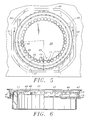
- Figure 5 is a plan view illustrating a portion of the top face of the chemical analyzer, and showing the drive wheel with the sample wheel located in the drive wheel.
- Figure 6 is a side view of the drive wheel and sample wheel, partly in section, the section being along line 6 - 6 of Figure 5.
- Figure 7 is a partial plan view illustrating the relationship of the drive wheel with the cam and restraining pins, the cam being in a position at the peak of a lobe on the drive wheel.
- Figure 8 is a partial plan view, with parts broken away, illustrating the relationship of the cam with the drive wheel, the cam being located in a valley between adjacent lobes of the drive wheel.
- Figure 9 is a partial plan view, with parts broken away, illustrating the cam relationship with the cam in a valley adjacent the valley of Figure 8.
- Figure 10 is a partial plan view, with parts broken away, of the drive wheel in relationship with the cam, and showing the cam located at the peak of a lobe in the drive wheel, and a shaft extension from a drive motor located in a locking notch on the drive wheel. The position in the cycle of motion is the same as depicted in Figure 7, namely the peak position between the locations illustrated in Figures 8 and 9.
- Figure 11 is a diagrammatic plan view illustrating the cycloidal motion of reaction cups in the sample wheel contained in the drive wheel.
- An automatic
clinical chemistry analyzer 10 includesdiscrete elements 11 located in a row on abody 12 which is a sample wheel or carousel. The discrete elements are sample cups orcontainers 11 mounted in asample wheel 12 which is in turn mounted in adrive wheel 13. - Means for progressively moving the
elements 11 towards and from atarget location 14 includes a motor means 15 mounted below aplate 16. The motor means 15 rotates acam 17 and a bearingsurface 18 of thecam 17 engages afollower surface 19 on thedrive wheel 13. Engagement of the bearingsurface 18 with thefollower surface 19 moves thebody 13 laterally and transversely towards thetarget location 14 during a first predetermined portion of travel of thecam 17. During a second predetermined portion of travel of thecam 17, thedrive wheel 13 is laterally and transversely moved away from thetarget location 14. Thedrive wheel 13 remains in a position removed from thetarget location 14 during a third predetermined portion of travel of thecam 17. - During this first, second and third predetermined portions of travel, the sample cups 11 follow a travel path which is respectively a first quarter
circular path 20 and a second quartercircular path 21. The two quartercircular paths cam 17, thecups 11 remain stationary. Thecam 17 travels the remainder of the semi-circular path thereby to close the circle with the quartercircular paths cups 11 which is cycloidal. This is indicated in Figure 11. Thecam 17 transcribes a circular path under driven action from themotor 15 about the axis ofshaft 22 which extends from agear box 23 connected with and mounted downstream themotor 15. - The
target location 14 is located adjacent aninjection cell 24 which is mounted below theaperture 25 in the base 26 at the top of theclinical analyzer 10. Aprobe 27 is mounted on acrane 28 to transfer fluid from the sample cups 11 to theinlet port 29 of theinjection cell 24. Thecrane 28 is selectively movable between the sample cups 11 and theinjection cell 24. - The
outer periphery 19 of thedrive wheel 13 includeslobes 30 which act as a cam follower. The lobes have a generally sinusoidal track around the circumference of thedrive wheel 13. The outer periphery of thelobes 30 has agreater radius 31 than thevalleys 32 of thelobes 30. - Pin means 33 at the extremities of a pair of restraining levers 34 acts to urge the
drive wheel 13 towards themotor 15. Thelevers 34 are mounted aboutpivots 35 and aspring connection 36 fixed topins 37 acts to draw thedrive wheel 13 towards therotor 15. Thus, when thewheel 13 is forced away from the motor under the action of thecam 17, the force frompins 33 urge and returns thedrive wheel 13 in the direction of themotor 15. Thepins 37 engage theinner surface 38 of thedrive wheel 13. Thedrive wheel 13 reacts with thecam 18 and the counterforce pins 33, to effect the cycloidal action. - The
drive wheel 13 rests on abase 39 and is constrained to substantially rotational movement on thebase 39. Such rotational movement is constituted by lateral and transverse motion as defined in the first predetermined portion of travel and the second predetermined portion of travel. Thebase 39 includesside walls wheel 13 from lateral movement beyond the rotational movement. Effectively,side walls side wall 40, together with thepins 33, can act to limit movement away from themotor 15. - A cycloidal motion is accomplished on the
sample wheel 12 which is housed in thedrive wheel 13. In this manner, thesample receptacles 11 simultaneously transverse a cycloidal path. The receptacles orcups 11, move laterally and transversely towards and away from thetarget location 14 in this cycloidal fashion. - A single motive means 15 effects both rotational movement of the
drive wheel 13 andsample wheel 12 and also movement towards and away from thetarget location 14. The combination of the lateral and transverse motions create the requisite rotational cycloidal movement of thedrive wheel 13. The single motive means 15 achieves this. Asingle crane motor 43 operative withcrane 28, causes vertical upwards and downwards motion of thecrane 28. The requisite rotational cycloidal motion and the vertical motion of thecrane 28 is thereby accomplished with only two motors, namely,motors - In a first exemplary position of the cycle, there is illustrated in Figure 8 the
cam 17 with the bearingsurface 18 and thevalley 32 oflobe 30 of thedrive wheel 13. The drivemotor shaft extension 22 from thegear box 23 is located in anotch 44 which are selectively arranged in predetermined locations about thedrive wheel 13. Thenotches 44 are spaced circumferentially from each other and inwardly of thelobes 30. Rotation of thecam 17 through one rotation advances thedrive wheel 13 through one increment and thesample wheel 12 is similarly moved through one increment. Movement of one increment would progressively locateadjacent cups 11 in thetarget location 14. - During the half revolution of the
cam 17, the bearingsurface 18 tracks from thevalley 32a illustrated in Figures 8 and 10 to thevalley 32b following thepeak 30 of thefollower 31. The extension ofshaft 22 is anchored in thenotch 44 during this movement, and thedrive wheel 13 is thus stationary. This movement of thecam 17 equates to the closing a semi-circle, namely, during the third predetermined travel path. - When the bearing
surface 18 engages thevalley 32b, as illustrated in Figure 9, thedrive wheel 13 is pushed forwardly, transversely and laterally towards thetarget location 14. This movement is away from themotor 15. This would correspond to the first predetermined portion oftravel 20 of thecups 11. Thenotch 44 is disengaged. As the travel of thecam 17 continues through the next quarter-circle corresponding to thetravel path 21, the bearingsurface 18 moves thevalley 32b in a transverse and lateral direction away from thetarget location 14. This movement continues until theshaft extension 22 engages in the notch 44b illustrated in Figure 9. In this action, the element is passing through the second predetermined travel path. The motion of thecups 11 is towards themotor 15 under the action of the restraining or counterforce pins 33. - Thereafter, the cycle, illustrated progressively in Figure 8 to Figure 10 to Figure 9 is repeated. The counterforce pins 33 continue to urge the
drive wheel 13 towards thecam 17 andmotor 15. During this time, thecups 11 traverse the cycloidal path illustrated in Figure 11. Eachcup 11 is, in turn, brought into thetarget location 14 for sampling by theprobe 27 and when moved out of thetarget location 14, theprobe 27 then enters the injection cell by descending throughport 29. - The
sample probe 27 is affixed to thecrane mechanism 28 which holds theprobe 27 in alignment withinjection cell 24 mounted below theplate 26. This is located below thedrive wheel 13 andsample wheel 12 mounted circumferentially about, within and on thedrive wheel 13. Theinjection cell 24 is accessed through theaperture 25 at thetarget location 14. Theprobe 27 motion is vertical only. - The sample or receptacle cups or
tubes 11 are mounted in discrete locations about the circumferential periphery of thesample wheel 12. Thecups 11 are moved into position by the cycloidal motion of thesample wheel 12 as generated by thedrive wheel 13. Thesample wheel 12 follows a path indicated bylines cups 11 from removed positions closer to the front face ormotor 15 and away from thetarget location 14 to positions above the target location. When removed from thetarget location 14, theprobe 27 descends into theport 29 of theinjection cell 24. When located over thetarget location 14, theprobe 27 enters thesample cup 11 which is located over thetarget location 14. The timing of the probe movement and action and thesample wheel 12 anddrive wheel 13 action is under regulating and control of a microprocessor. - The
cups 11 thereby effect the lateral and transverse motions which constitute the rotational motion of thesample wheel 12. The lateral motion is partly defined between theside walls forward wall 45 andrear wall 40 housing thedrive wheel 13 andsample wheel 12. The vertical motion is provided by thecrane 28 operating theprobe 27. Accordingly, only twomotors sample wheel 13 rotationally and cycloidally. Vertical action removes samples from thecups 11 and dispenses them into theinjection cell 24. This saves the complexity of three motive forces and improves reliability and reduces costs. - In Figure 11, the positions between the respective semi-circles constituted by quarter-
circles cups 11 where the sample is removed by theprobe 27. In this position, thecam 17 operates through its third portion of travel. Thecups 11 are stationary and removed from thetarget location 14, and theprobe 27 aspirates into theinjection cell 24. - In Figures 4 and 5, there is diagrammatically illustrated in two of the
cups 11acircular sleeve adapter 111 which would be used within the periphery of theelements 11 to accommodatecups 11. In other cases, thesleeve adapters 111 could be used withsmaller diameter tubes 11 which fit into the apertures about thesample wheel 13. -
Discrete apertures 46 and periodically discretely spacedflags 47 are located about thesample wheel 12. The spacedapertures 46 andflags 47 are irregularly located in predetermined spaced manner about the outsidecircumference side wall 49 of thesample wheel 12. - Adjacent the
front face 45 and below thetop plate 146 of the analyzer are a series of sixsensor units 48 spaced discretely and separately about the circumference of thesample wheel 12. The spacing is designed to correspond with the predetermined irregular spacing ofapertures 46 andflags 47 onsample wheel 12. Thesensor units 48 are of an optical nature and each include transmitter and receiver elements which depend on the reflectivity from theflags 47 of thesample wheel 12. Signal enhancement means is provided for thesensor units 48. - Effectively, maximum reflection is achieved by the
flags 47 and minimum reflection is achieved due to theapertures 46. Thesample tray wheel 12 thereby has molded as part of theside wall 49 the means for coding the location of the discrete sample cups 11. The relationship of thesample wheel 12 anddrive wheel 13 is such that thesample wheel 12 is randomly located inside thedrive wheel 13. Theside wall 49 has at least that portion having theapertures 46 andflags 47 optically directed to thesensor unit 48. Thus thesample wheel 12 acts inherently to code for location of thecups 11 within thewheel 12. There are 40sample cells 11 arranged around the circumference of thesample wheel 12 which can be coded and identified by the sixsensor units 48. - The
sensor units 48 are mounted on acircuit board 50 which interfaces at 51 with acable 52 to amicroprocessor 152. Themicroprocessor 152 can also constitute part of the control system for regulating the motion of thedrive wheel 13,crane 28, and probe 27 operation with thecups 11 andinjection cell 24. - As the
sample tray 12 moves driven by thedrive wheel 13, theapertures 46 andflags 47 move in a rotational fashion before the sixsensor units 48. Periodic starting and stopping of thedrive wheel 13 is effected. - A
sensor 153 interacts withtab 154 on thecam 17 such that when thedrive wheel 13 is in the position indicated in Figure 10 reading of theapertures 46 andflags 47 can be effected. This would correspond to the position of thecups 11 removed from thetarget 14. In the positions illustrated in Figures 8 and 9 of thecam 17 thetab 154 is removed from thesensor 153. Thesensors 48 do not read theapertures 46 andflags 47 in this position of thesample tray 12 anddrive wheel 13. - A parallel decoding method is employed and a binary system is effective for coding. Reflectance is achieved when a
flag 47 is before asensor 48. This would be represented as a binary digit 0. Non-reflectance before asensor 48 digit is indicative of anaperture 46 before thesensor 48. This is indicative of adigit 1. Thesensor 53 is the most significant bit sensor and thesensor 54 is the least significant bit sensor. - The
target location 14 is also illustrated in Figure 4. As illustrated in Figure 4, thesample wheel 12 is in a position ready to move to thetarget location 14 where theprobe 27 can remove the sample from sample cup 11A. - The binary positions can be represented by the following table:
Position # Code Binary Code (LSB -MSB) Position # Binary 1 000000 21 000011 2 000001 22 000110 3 000010 23 001101 4 000101 24 011010 5 001010 25 110101 6 010101 26 101010 7 101011 27 010100 8 010111 28 101000 9 101111 29 010001 10 011111 30 100010 11 111110 31 000100 12 111101 32 001001 13 111010 33 010011 14 110100 34 100111 15 101001 35 001111 16 010010 36 011110 17 100100 37 111100 18 001000 38 111000 19 010000 39 110000 20 100001 40 100000 - The advantage of the coding system is that the necessary components are formed or mounted integrally with the
sample wheel 12, which is rugged and durable. Protection against wear and chemicals is strong and effective, and there is no assembly nor the necessity to add stickers for coding. The system also provides for ease of application since the selectedsample wheel 12 need simply be randomly located in thedrive wheel 13 in any position. Theapertures 46 andflags 47 are aligned withsensors 48 as required. The coding identification is straightforward and it is easy to index and identify whichparticular sample cup 11 relative to the code is to be accessed and analyzed. - With the above arrangement, the
drive wheel 13 can be operated in either a clockwise or counterclockwise motion. It is always possible to identify easily therequisite sample cup 11 for analysis. By having two separate components, namely, thedrive wheel 13 andsample wheel 12, the mechanism is easily operated.Different sample wheels 12 can be inserted with thedrive wheel 13 as required with a minimum downtime. - Many other examples of the invention exist, each differing from the others in matters of detail only. For instance, although a drive wheel and sample wheel are illustrated the operation of the components with the cam could be with the reaction cups located in a linear, non-circular manner relative to the handling system. Similarly, the coding procedure for the
sample wheel 12 can operate with configurations other than circular. The scope of the invention is to be determined sole by the appended claims.
Claims (20)
Applications Claiming Priority (2)
| Application Number | Priority Date | Filing Date | Title |
|---|---|---|---|
| US32281489A | 1989-03-13 | 1989-03-13 | |
| US322814 | 1989-03-13 |
Publications (2)
| Publication Number | Publication Date |
|---|---|
| EP0388012A2 true EP0388012A2 (en) | 1990-09-19 |
| EP0388012A3 EP0388012A3 (en) | 1991-05-22 |
Family
ID=23256548
Family Applications (1)
| Application Number | Title | Priority Date | Filing Date |
|---|---|---|---|
| EP19900301620 Withdrawn EP0388012A3 (en) | 1989-03-13 | 1990-02-15 | Sample handling for chemistry analyzers |
Country Status (2)
| Country | Link |
|---|---|
| EP (1) | EP0388012A3 (en) |
| JP (1) | JPH02118867U (en) |
Family Cites Families (2)
| Publication number | Priority date | Publication date | Assignee | Title |
|---|---|---|---|---|
| US3853010A (en) * | 1973-03-05 | 1974-12-10 | Varian Associates | Sample container support with coding means |
| GB2125961B (en) * | 1982-08-20 | 1985-10-09 | Philips Electronic Associated | Automatic sampling arrangement turntable |
-
1990
- 1990-02-02 JP JP903090U patent/JPH02118867U/ja active Pending
- 1990-02-15 EP EP19900301620 patent/EP0388012A3/en not_active Withdrawn
Non-Patent Citations (1)
| Title |
|---|
| IBM TECHNICAL DISCLOSURE BULLETIN, vol. 26, no. 6, November 1983, pages 2868-2869, New York, US; F.L. CONRAD et al.: "Spiral feed auto sample handler" * |
Also Published As
| Publication number | Publication date |
|---|---|
| EP0388012A3 (en) | 1991-05-22 |
| JPH02118867U (en) | 1990-09-25 |
Similar Documents
| Publication | Publication Date | Title |
|---|---|---|
| EP0388013A2 (en) | Sample wheel for chemical analyzers | |
| US5204269A (en) | Sample handling for chemistry analyzers | |
| EP1678509B1 (en) | Device for performing analyses on biological fluids and related method | |
| EP1465728B1 (en) | Stackable aliquot vessel array | |
| US4861553A (en) | Automatic sampling system | |
| US6375898B1 (en) | Analysis system | |
| US4595562A (en) | Loading and transfer assembly for chemical analyzer | |
| EP0825445B1 (en) | Automatic biochemical analyzer | |
| US5270211A (en) | Sample tube entry port for a chemical analyzer | |
| US20030049170A1 (en) | Transfer unit and automatic analyzing apparatus having such transfer unit | |
| CA2271812C (en) | Automatic chemistry analyzer with sample cup stopper piercing assembly | |
| US5942694A (en) | Pressure detector for chemical analyzers | |
| JPH01219669A (en) | Detecting method of liquid sample vessel according to assortment | |
| EP0692717B1 (en) | Analysis instrument | |
| JPH0266461A (en) | Automatic analyzer | |
| US5223222A (en) | Automatic chemistry analyzer | |
| EP0388012A2 (en) | Sample handling for chemistry analyzers | |
| EP0660115A2 (en) | Automatic chemistry analyzer | |
| EP0388015A2 (en) | Sample identification in chemistry analyzers | |
| IE904228A1 (en) | Sample handling system for an optical monitoring system | |
| US6513716B2 (en) | Automatic apparatus for reading bar codes and an automatic analyzer provided therewith | |
| WO2005009212A2 (en) | Bi-directional drivebelt tensioning device | |
| JP2547406Y2 (en) | Automatic analyzer | |
| JPS61247971A (en) | Automatic analyzing device | |
| JPH0115029B2 (en) |
Legal Events
| Date | Code | Title | Description |
|---|---|---|---|
| PUAI | Public reference made under article 153(3) epc to a published international application that has entered the european phase |
Free format text: ORIGINAL CODE: 0009012 |
|
| AK | Designated contracting states |
Kind code of ref document: A2 Designated state(s): DE ES FR GB IT |
|
| PUAL | Search report despatched |
Free format text: ORIGINAL CODE: 0009013 |
|
| AK | Designated contracting states |
Kind code of ref document: A3 Designated state(s): DE ES FR GB IT |
|
| 17P | Request for examination filed |
Effective date: 19910705 |
|
| 17Q | First examination report despatched |
Effective date: 19921209 |
|
| STAA | Information on the status of an ep patent application or granted ep patent |
Free format text: STATUS: THE APPLICATION IS DEEMED TO BE WITHDRAWN |
|
| 18D | Application deemed to be withdrawn |
Effective date: 19950412 |