EP0387987A2 - Stabilizer ring for a fan-mounting apparatus - Google Patents
Stabilizer ring for a fan-mounting apparatus Download PDFInfo
- Publication number
- EP0387987A2 EP0387987A2 EP90300979A EP90300979A EP0387987A2 EP 0387987 A2 EP0387987 A2 EP 0387987A2 EP 90300979 A EP90300979 A EP 90300979A EP 90300979 A EP90300979 A EP 90300979A EP 0387987 A2 EP0387987 A2 EP 0387987A2
- Authority
- EP
- European Patent Office
- Prior art keywords
- fan
- mounting apparatus
- ring
- inner ring
- support
- Prior art date
- Legal status (The legal status is an assumption and is not a legal conclusion. Google has not performed a legal analysis and makes no representation as to the accuracy of the status listed.)
- Withdrawn
Links
Images
Classifications
-
- F—MECHANICAL ENGINEERING; LIGHTING; HEATING; WEAPONS; BLASTING
- F04—POSITIVE - DISPLACEMENT MACHINES FOR LIQUIDS; PUMPS FOR LIQUIDS OR ELASTIC FLUIDS
- F04D—NON-POSITIVE-DISPLACEMENT PUMPS
- F04D29/00—Details, component parts, or accessories
- F04D29/40—Casings; Connections of working fluid
- F04D29/52—Casings; Connections of working fluid for axial pumps
- F04D29/54—Fluid-guiding means, e.g. diffusers
- F04D29/541—Specially adapted for elastic fluid pumps
- F04D29/542—Bladed diffusers
- F04D29/544—Blade shapes
Definitions
- the present invention relates generally to automotive engine cooling systems as specified in the preamble of Claim 1, for example as disclosed in US-A-4,548 548, and in particular is concerned with a stabilizer element added to a mounting apparatus for an automotive engine cooling fan to strengthen the mounting apparatus.
- engine cooling systems for automotive vehicles include a fan for increasing the quantity of airflow through a radiator.
- An engine cooling fan is mounted on a bracket or shroud adjacent a radiator.
- Such fans may be driven by mechanical connection to an engine shaft or by other means, e.g. electric current.
- an engine cooling fan produces two types of airflow from the fan blades. First, axial airflow is discharged from the fan blades in a direction generally parallel to the fan axis of rotation. Second, radial airflow is discharged from the fan blades in a direction generally perpendicular to the fan axis of rotation. Whilst axial airflow provides the majority of cooling air in an engine compartment, radial airflow provides only a minimal cooling effect.
- a fan-mounting apparatus i.e. a bracket, or a shroud
- the mounting apparatus would be constructed from minimal mass and be capable of withstanding the torsional stresses induced by airflow and vibrations from the fan.
- improved mounting brackets and shrouds redirect the radial airflow to axial airflow to increase the cooling effect of the system.
- airflow noise from a strengthened mounting apparatus be no greater than the noise associated with conventional shrouds and brackets.
- a fan-mounting apparatus is characterised by the features specified in the characterising portion of claim 1.
- the present invention includes a stabilizer element added to a shroud or bracket for strengthening the mounting apparatus.
- the present stabilizer redirects radial airflow to axial airflow to increase fan efficiency.
- the present stabilizer is economical and can be incorporated with conventional mounting brackets and shrouds, and does not add any appreciable noise from airflow.
- the present invention includes a mounting bracket for an engine cooling fan.
- a central hub removably receives the fan.
- Support vanes extend radially from the hub to an outer support ring.
- At least one inner ring is provided between the hub and the outer support ring.
- Each inner ring includes a surface for redirecting radial airflow to axial airflow.
- the stabilizer element can be formed as a ring or circular element, or as a plurality of arcuate portions spaced at selected radii from the central hub.
- the cross-section and radius of each arcuate section can be selected to optimize a desired function, e.g. structural re-inforcement, redirection of radial airflow or noise abatement.
- a stabilizer element according to the present invention is incorporated in a fan shroud ( Figures 1-2) and in a pair of mounting brackets ( Figures 8 and 9). It should be understood that the stabilizer element according to the present invention can be incorporated in any selected conventional fan-mounting apparatus.
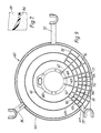
- a first preferred embodiment of the present invention is incorporated in a shroud, indicated generally at 10 in Figures 1 and 2.
- Shroud 10 can be formed from any suitable plastics or mouldable material and includes a rectilinear face plate 12 bounded by a peripheral and forwardly-extending wall 14.
- Shroud 10 can be mounted in an engine compartment adjacent a radiator (not illustrated) by conventional fasteners (not illustrated) at mounting ears 16. If desired, various mounting ears and brackets can be incorporated with shroud 10 to facilitate mounting in an engine compartment.
- Face plate 12 includes a rearwardly-extending cylindrical ejector 18 which forms the rear, discharge end of shroud 10.
- the diameter of ejector 18 is slightly greater than the diameter of the blades of a fan 101 (illustrated only in Figure 1).
- Ejector 18 includes an outwardly-flaring bellmouth portion 20.
- Fan 101 is removably mounted on support collar 22 by conventional fasteners (not illustrated). Fan 101 can be driven by a conventional electric motor or can be mechanically connected to an engine power shaft. As fan 101 is rotated, air is pulled from the radiator side of shroud 10 through ejector 18 and blown onto an engine.
- Axial airflow 102 which is generally parallel to a fan axis of rotation 103, provides the major portion of the cooling effect.
- a plurality of radially-extending stator vanes 24 are provided between the support collar 22 and ejector 18.
- Each vane 24 is a planar member having ends integrally moulded with the support collar 22 and ejector 18.
- a concentric, stabilizer ring 26 is provided between vanes 24.
- Ring 26 is formed from a mouldable, plastics material and can be integrally moulded with vanes 24. Ring 26 performs two major purposes. Firstly, ring 26 stabilizes vanes 24 against torsional stresses induced from airflow, thereby increasing the structural integrity of shroud 10. Secondly, ring 26 redirects radial airflow to axial airflow, and thereby improves the cooling efficiency of the fan 101.
- ring 26 can vary, depending upon which function of the ring is to be maximized.
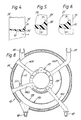
- the ring 26, illustrated in detail in Figures 3A and 3B is a curved member having a thickness T and a face 27 of a width W equal to the width of vanes 24. As illustrated in Figure 3B, when radial airflow 104 encounters face 27, it is redirected to axial airflow 102.
- ring 26 has a diameter approximately 60-70% the diameter of the ejector 18. In other embodiments, ring 26 may have a diameter in a range of 10-90% of the diameter of ejector 18. For example, in most fans, the airflow discharged near an outer tip of a fan blade is greater than the airflow discharged near a hub of the fan. If it is preferred to maximize the redirection of radial airflow 104 to axial airflow 102, ring 26 would be positioned in the maximum zone of radial airflow 104. In another example, the stabilization effect of ring 26 may require that ring 26 be positioned at a point other than the point of maximum radial airflow 104.
- ring 30 includes a sloped leading edge 31 which acts as a scoop for receiving airflow from fan 101.
- Ring edge 32 is bounded by end surface 34. Ring edge 32 is provided at an acute angle A with respect to the end surface 34 of vane 24 and ring 30 is oriented with respect to vanes 24 to redirect radial airflow.
- ring edge 32 is provided flush with end surface 34.
- ring edge 32 is parallel to and laterally-spaced from end surface 34.
- a ring 36 having a well-known airfoil shape and cross section is illustrated.
- a selected ring element can be integrally moulded with vanes 24 at a selected radius from the fan axis of rotation.
- Bracket 40 includes a central support collar 42 for removably mounting a fan.
- An outer support ring 44 is provided at approximately the outer tips of a mounted fan (not illustrated).
- Support vanes 46A-46D having mounting ears 48 extend radially from support collar 42. If desired, support collar 42, outer ring 44, vanes 46A-46D and mounting ears 48 can be integrally moulded.
- a stabilization ring element 50 is provided between support collar 42 and outer ring 44.
- ring 50 can be less than 360° and can be formed from a plurality of arcuate portions as illustrated in Figure 8, wherein ring element 50 is not provided between vanes 46A and 46B.
- ring element 50 can be provided in sections of varying diameter. For example, ring sections 51 and 54 are provided at a smaller radius than ring section 53.
- Various configurations, cross-sections and shapes of ring element 50 can be provided, depending upon the needs of a particular mounting bracket. Elements such as a mounting tab 52 or section 51 can be moulded with any section on ring element 50.
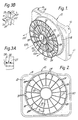
- FIG 9 illustrates a second embodiment of a mounting bracket 60 incorporating multiple, concentric stabilizer rings 61, 62, 63 and 64.
- Bracket 60 includes a support collar 66 having radially extending support vanes 67, 68, and 69 connected to an outer support ring 70.
- Various mounting ears 72, 73 and 74 are connected to the outer support ring 70.
- bracket 60 can be moulded as an integral unit.
- Control rings 61 and 63 are provided at selected radii from the centrepoint of support collar 66.
- Control rings 62 and 64 are provided at a selected portion of the radial distance about support collar 66.
- Various support vanes 75-83 are selectively spaced between control rings 61 and the outer support ring 70. Rings 61, 62, 63 and 64 are selectively positioned to stabilize bracket 60 and redirect radial airflow from a fan blade to axial airflow to improve fan efficiency.
- Each stabilizer ring can be positioned and shaped to maximize the function of stabilization and/or airflow redirection whilst minimizing additional noise.
Landscapes
- Engineering & Computer Science (AREA)
- Mechanical Engineering (AREA)
- General Engineering & Computer Science (AREA)
- Physics & Mathematics (AREA)
- Geometry (AREA)
- Structures Of Non-Positive Displacement Pumps (AREA)
Abstract
A mounting bracket (10) for an engine cooling fan includes a central hub (22) for removably receiving the fan. Support vanes (24) extend radially from the hub (22) to an outer support ring (18). At least one inner ring (26) is provided between the hub (22) and the outer support ring (18). Each inner ring (26) includes a surface for redirecting radial airflow to axial airflow.
Description
- The present invention relates generally to automotive engine cooling systems as specified in the preamble of Claim 1, for example as disclosed in US-A-4,548 548, and in particular is concerned with a stabilizer element added to a mounting apparatus for an automotive engine cooling fan to strengthen the mounting apparatus.
- Many engine cooling systems for automotive vehicles include a fan for increasing the quantity of airflow through a radiator. An engine cooling fan is mounted on a bracket or shroud adjacent a radiator. Such fans may be driven by mechanical connection to an engine shaft or by other means, e.g. electric current.
- Generally, an engine cooling fan produces two types of airflow from the fan blades. First, axial airflow is discharged from the fan blades in a direction generally parallel to the fan axis of rotation. Second, radial airflow is discharged from the fan blades in a direction generally perpendicular to the fan axis of rotation. Whilst axial airflow provides the majority of cooling air in an engine compartment, radial airflow provides only a minimal cooling effect.
- The art continues to seek improvements. It is desirable that a fan-mounting apparatus, i.e. a bracket, or a shroud, provide the necessary support for a fan whilst contributing as little weight as possible to the system. Ideally, the mounting apparatus would be constructed from minimal mass and be capable of withstanding the torsional stresses induced by airflow and vibrations from the fan. Furthermore, it is desirable that improved mounting brackets and shrouds redirect the radial airflow to axial airflow to increase the cooling effect of the system. It is also desirable that airflow noise from a strengthened mounting apparatus be no greater than the noise associated with conventional shrouds and brackets.
- A fan-mounting apparatus according to the present invention is characterised by the features specified in the characterising portion of claim 1.
- The present invention includes a stabilizer element added to a shroud or bracket for strengthening the mounting apparatus. The present stabilizer redirects radial airflow to axial airflow to increase fan efficiency. The present stabilizer is economical and can be incorporated with conventional mounting brackets and shrouds, and does not add any appreciable noise from airflow.
- In a preferred embodiment, the present invention includes a mounting bracket for an engine cooling fan. A central hub removably receives the fan. Support vanes extend radially from the hub to an outer support ring. At least one inner ring is provided between the hub and the outer support ring. Each inner ring includes a surface for redirecting radial airflow to axial airflow.
- In various embodiments of the invention, the stabilizer element can be formed as a ring or circular element, or as a plurality of arcuate portions spaced at selected radii from the central hub. The cross-section and radius of each arcuate section can be selected to optimize a desired function, e.g. structural re-inforcement, redirection of radial airflow or noise abatement.
-
- Figure 1 is a perspective view illustrating a fan mounted on a shroud utilizing a first embodiment of a stabilizer ring according to the present invention.
- Figure 2 is a rear elevational view of the shroud of Figure 1 wherein the fan has been removed for purposes of clarity of illustration.
- Figure 3A is an enlarged sectional view taken along line 3-3 of Figure 2.
- Figure 3B is a perspective view of a portion of the ring in Figure 3A.
- Figures 4-7 are enlarged sectional views of alternative shapes of the ring shown in Figure 1.
- Figure 8 is a rear elevational view of a mounting bracket incorporating an alternative embodiment of a ring according to the present invention.
- Figure 9 is a rear elevational view of a second embodiment of a mounting bracket incorporating a plurality of rings according to the present invention.
- For purposes of this disclosure, a stabilizer element according to the present invention is incorporated in a fan shroud (Figures 1-2) and in a pair of mounting brackets (Figures 8 and 9). It should be understood that the stabilizer element according to the present invention can be incorporated in any selected conventional fan-mounting apparatus.
- A first preferred embodiment of the present invention is incorporated in a shroud, indicated generally at 10 in Figures 1 and 2.
Shroud 10 can be formed from any suitable plastics or mouldable material and includes arectilinear face plate 12 bounded by a peripheral and forwardly-extendingwall 14. Shroud 10 can be mounted in an engine compartment adjacent a radiator (not illustrated) by conventional fasteners (not illustrated) at mountingears 16. If desired, various mounting ears and brackets can be incorporated withshroud 10 to facilitate mounting in an engine compartment. -
Face plate 12 includes a rearwardly-extendingcylindrical ejector 18 which forms the rear, discharge end ofshroud 10. Preferably, the diameter ofejector 18 is slightly greater than the diameter of the blades of a fan 101 (illustrated only in Figure 1).Ejector 18 includes an outwardly-flaringbellmouth portion 20. Fan 101 is removably mounted onsupport collar 22 by conventional fasteners (not illustrated). Fan 101 can be driven by a conventional electric motor or can be mechanically connected to an engine power shaft. As fan 101 is rotated, air is pulled from the radiator side ofshroud 10 throughejector 18 and blown onto an engine.Axial airflow 102, which is generally parallel to a fan axis of rotation 103, provides the major portion of the cooling effect. - A plurality of radially-extending
stator vanes 24 are provided between thesupport collar 22 andejector 18. Eachvane 24 is a planar member having ends integrally moulded with thesupport collar 22 andejector 18. - In the
shroud 10 of Figures 1-2, a concentric,stabilizer ring 26 is provided betweenvanes 24.Ring 26 is formed from a mouldable, plastics material and can be integrally moulded withvanes 24. Ring 26 performs two major purposes. Firstly,ring 26 stabilizesvanes 24 against torsional stresses induced from airflow, thereby increasing the structural integrity ofshroud 10. Secondly,ring 26 redirects radial airflow to axial airflow, and thereby improves the cooling efficiency of the fan 101. - The specific shape and location of
ring 26 can vary, depending upon which function of the ring is to be maximized. For example, thering 26, illustrated in detail in Figures 3A and 3B, is a curved member having a thickness T and aface 27 of a width W equal to the width ofvanes 24. As illustrated in Figure 3B, whenradial airflow 104encounters face 27, it is redirected toaxial airflow 102. - In the example illustrated in Figures 1 and 2,
ring 26 has a diameter approximately 60-70% the diameter of theejector 18. In other embodiments,ring 26 may have a diameter in a range of 10-90% of the diameter ofejector 18. For example, in most fans, the airflow discharged near an outer tip of a fan blade is greater than the airflow discharged near a hub of the fan. If it is preferred to maximize the redirection ofradial airflow 104 toaxial airflow 102,ring 26 would be positioned in the maximum zone ofradial airflow 104. In another example, the stabilization effect ofring 26 may require thatring 26 be positioned at a point other than the point of maximumradial airflow 104. - Alternative cross-sections and shapes of
ring 26 are illustrated in Figures 4, 5, 6 and 7. In Figure 4,ring 30 includes a sloped leading edge 31 which acts as a scoop for receiving airflow from fan 101.Ring edge 32 is bounded byend surface 34.Ring edge 32 is provided at an acute angle A with respect to theend surface 34 ofvane 24 andring 30 is oriented with respect tovanes 24 to redirect radial airflow. - In Figure 5, which has been greatly enlarged for purposes of clarity of illustration,
ring edge 32 is provided flush withend surface 34. In Figure 6,ring edge 32 is parallel to and laterally-spaced fromend surface 34. In Figure 7, aring 36 having a well-known airfoil shape and cross section is illustrated. Various modifications to a ring can be made to enhance its ability to capture and redirectradial airflow 104. A selected ring element can be integrally moulded withvanes 24 at a selected radius from the fan axis of rotation. - A first embodiment of a fan-mounting
bracket 40 is illustrated in Figure 8.Bracket 40 includes a central support collar 42 for removably mounting a fan. Anouter support ring 44 is provided at approximately the outer tips of a mounted fan (not illustrated).Support vanes 46A-46D having mountingears 48 extend radially from support collar 42. If desired, support collar 42,outer ring 44,vanes 46A-46D and mountingears 48 can be integrally moulded. - A
stabilization ring element 50 is provided between support collar 42 andouter ring 44. If desired,ring 50 can be less than 360° and can be formed from a plurality of arcuate portions as illustrated in Figure 8, whereinring element 50 is not provided betweenvanes ring element 50 can be provided in sections of varying diameter. For example,ring sections 51 and 54 are provided at a smaller radius thanring section 53. Various configurations, cross-sections and shapes ofring element 50 can be provided, depending upon the needs of a particular mounting bracket. Elements such as a mountingtab 52 or section 51 can be moulded with any section onring element 50. - Figure 9 illustrates a second embodiment of a mounting
bracket 60 incorporating multiple, concentric stabilizer rings 61, 62, 63 and 64.Bracket 60 includes a support collar 66 having radially extendingsupport vanes outer support ring 70. Various mountingears outer support ring 70. If desired,bracket 60 can be moulded as an integral unit. - Control rings 61 and 63 are provided at selected radii from the centrepoint of support collar 66. Control rings 62 and 64 are provided at a selected portion of the radial distance about support collar 66. Various support vanes 75-83 are selectively spaced between control rings 61 and the
outer support ring 70.Rings bracket 60 and redirect radial airflow from a fan blade to axial airflow to improve fan efficiency. - As stated above, various embodiments of the present stabilizer ring can be easily envisioned. Each stabilizer ring can be positioned and shaped to maximize the function of stabilization and/or airflow redirection whilst minimizing additional noise.
Claims (10)
1. A fan-mounting apparatus (10;40;60) for resisting torsional stresses induced by airflow, which apparatus (10;40;60) comprises a collar member (22;42;66) for removably receiving a fan; support members (24;46A,46B,46C,46D;67,68,69) extending radially from the collar member (22;42;66); and an outer ring member (20;44;70) located adjacent outer ends of the fan and connected to the support members (24;46A,46B,46C,46D;67,68,69), characterised in that the apparatus (10;40;60) also includes an inner ring member (26;50;61,62,63,64) extending at least partially concentrically about the collar member (22;42;66) at a selected distance between an outer circumference of the collar member (22;42;66) and an inner circumference of the outer ring member (20;44;70) to strengthen the apparatus, the inner ring member (26;50;61,62,63,64) being connected to the support members (24;46A,46B,46C,46D;67,68,69).
2. A fan-mounting apparatus (10) according to claim 1, in which the collar member (22), the support members (24) and the outer ring member (20) comprise a shroud.
3. A fan-mounting apparatus (10) according to claim 2, in which the support members (24) are support vanes extending radially from the collar member (22); and the inner ring member (26) has a surface oriented approximately parallel to the fan axis of rotation (103).
4. A fan-mounting apparatus (10) according to claim 3, in which the inner ring surface includes a sloped edge (31) for scooping air.
5. A fan-mounting apparatus (10) according to claim 4, in which the sloped edge (31) for scooping air extends at an acute angle (A) to an end surface (34) of each support vane (24).
6. A fan-mounting apparatus (10) according to claim 4, in which the sloped edge (31) for scooping air is flush with an end surface (34) of each support vane (24).
7. A fan-mounting apparatus (10) according to claim 4, in which the sloped edge (31) for scooping air is parallel to, and laterally-spaced from, an end surface (34) of each support vane (24).
8. A fan-mounting apparatus (60) according to claim 1, in which the apparatus includes bracket members (72,73,74) extending radially from the outer ring members (70).
9. A fan-mounting apparatus (40) according to claim 1, in which the inner ring member (50) comprises at least one circumferential arcuate member (51,52,53) having a surface oriented approximately parallel to the fan axis of rotation (103).
10. A fan-mounting apparatus (60) according to claim 1, in which the inner ring member comprises a plurality of concentric arcuate members (61,62,63,64) positioned at selected radii from the fan axis of rotation (103), each arcuate member (61,62,63,64) including a surface oriented approximately parallel to the fan axis of rotation (103).
Applications Claiming Priority (2)
| Application Number | Priority Date | Filing Date | Title |
|---|---|---|---|
| US32247589A | 1989-03-13 | 1989-03-13 | |
| US322475 | 1989-03-13 |
Publications (2)
| Publication Number | Publication Date |
|---|---|
| EP0387987A2 true EP0387987A2 (en) | 1990-09-19 |
| EP0387987A3 EP0387987A3 (en) | 1990-11-28 |
Family
ID=23255073
Family Applications (1)
| Application Number | Title | Priority Date | Filing Date |
|---|---|---|---|
| EP19900300979 Withdrawn EP0387987A3 (en) | 1989-03-13 | 1990-01-31 | Stabilizer ring for a fan-mounting apparatus |
Country Status (2)
| Country | Link |
|---|---|
| EP (1) | EP0387987A3 (en) |
| JP (1) | JPH02275098A (en) |
Cited By (16)
| Publication number | Priority date | Publication date | Assignee | Title |
|---|---|---|---|---|
| EP0547253A1 (en) * | 1991-12-14 | 1993-06-23 | Süd-Electric GmbH | Flow director for a fan |
| GB2290832A (en) * | 1994-06-14 | 1996-01-10 | Clive Felix Ure | Means for linearizing an open air flow |
| US5498130A (en) * | 1994-10-18 | 1996-03-12 | Itt Automotive Electrical Systems Inc. | Cooling fan mounting system |
| GB2298458A (en) * | 1995-03-02 | 1996-09-04 | Lucas Aerospace Power Equip | Cooling electromechanical apparatus |
| GB2324572A (en) * | 1996-12-10 | 1998-10-28 | Papst Motoren Gmbh & Co Kg | Axial fan housing |
| FR2789450A1 (en) * | 1998-12-30 | 2000-08-11 | Valeo Thermique Moteur Sa | Stator for ventilator fan for motor vehicle air conditioning has surface area of stator blades less than thirty percent of surface area of rotor blades |
| DE19751042C2 (en) * | 1996-11-21 | 2002-04-25 | Zexel Valeo Climate Contr Corp | cooling fan |
| US6503060B1 (en) | 1999-08-09 | 2003-01-07 | Daikin Industries, Ltd. | Fan guard of blower unit and air conditioner |
| DE102005046180B3 (en) * | 2005-09-27 | 2007-03-22 | Siemens Ag | Fan module for cooling motor vehicle engines has a fan housing containing a fan motor and a fan wheel driven by the fan motor |
| CN103423206A (en) * | 2013-07-15 | 2013-12-04 | 中国第一汽车股份有限公司 | Rotating flow cover assembly of automotive fan and for cooling fan clutch compulsively |
| DE102012109542A1 (en) * | 2012-10-08 | 2014-04-10 | Ebm-Papst Mulfingen Gmbh & Co. Kg | "Flow straightener for an axial fan" |
| US20150275918A1 (en) * | 2014-03-27 | 2015-10-01 | Trane International Inc. | Diffuser collar |
| EP2357366A4 (en) * | 2008-12-05 | 2017-04-26 | Mitsubishi Heavy Industries, Ltd. | Heat exchange module for vehicle and vehicle with same |
| EP1750015A3 (en) * | 2005-08-03 | 2017-07-05 | Mitsubishi Heavy Industries, Ltd. | Shroud and rotary vane wheel of propeller fan and propeller fan |
| USD805107S1 (en) | 2016-12-02 | 2017-12-12 | U.S. Farathane Corporation | Engine fan shroud |
| CN110825195A (en) * | 2018-08-13 | 2020-02-21 | 钱军 | Computer case cooling fan |
Family Cites Families (2)
| Publication number | Priority date | Publication date | Assignee | Title |
|---|---|---|---|---|
| US3178099A (en) * | 1963-10-09 | 1965-04-13 | Lachlan W Child | Under-body ventilating fan units |
| FR2503280B1 (en) * | 1981-04-03 | 1986-04-11 | Etri Sa | FLAT TYPE FAN, ESPECIALLY FOR ELECTRONIC CIRCUITS |
-
1990
- 1990-01-31 EP EP19900300979 patent/EP0387987A3/en not_active Withdrawn
- 1990-03-12 JP JP2058247A patent/JPH02275098A/en active Pending
Cited By (24)
| Publication number | Priority date | Publication date | Assignee | Title |
|---|---|---|---|---|
| EP0547253A1 (en) * | 1991-12-14 | 1993-06-23 | Süd-Electric GmbH | Flow director for a fan |
| GB2290832A (en) * | 1994-06-14 | 1996-01-10 | Clive Felix Ure | Means for linearizing an open air flow |
| US5498130A (en) * | 1994-10-18 | 1996-03-12 | Itt Automotive Electrical Systems Inc. | Cooling fan mounting system |
| GB2298458A (en) * | 1995-03-02 | 1996-09-04 | Lucas Aerospace Power Equip | Cooling electromechanical apparatus |
| FR2731306A1 (en) * | 1995-03-02 | 1996-09-06 | Lucas Aerospace Power Equip | MONOBLOC COOLING AIR DIFFUSER FOR ELECTROMECHANICAL DEVICE |
| US5731644A (en) * | 1995-03-02 | 1998-03-24 | Lucas Aerospace Power Equipment Corporation | Integral cooling air diffuser for electromechanical apparatus |
| GB2298458B (en) * | 1995-03-02 | 1999-01-06 | Lucas Aerospace Power Equip | Integral cooling air diffuser for electromechanical apparatus |
| DE19751042C2 (en) * | 1996-11-21 | 2002-04-25 | Zexel Valeo Climate Contr Corp | cooling fan |
| GB2324572A (en) * | 1996-12-10 | 1998-10-28 | Papst Motoren Gmbh & Co Kg | Axial fan housing |
| US6017191A (en) * | 1996-12-10 | 2000-01-25 | Papst-Motoren Gmbh & Co. Kg | Axial ventilator housing |
| GB2324572B (en) * | 1996-12-10 | 2000-10-11 | Papst Motoren Gmbh & Co Kg | Axial fan housing |
| FR2789450A1 (en) * | 1998-12-30 | 2000-08-11 | Valeo Thermique Moteur Sa | Stator for ventilator fan for motor vehicle air conditioning has surface area of stator blades less than thirty percent of surface area of rotor blades |
| US6503060B1 (en) | 1999-08-09 | 2003-01-07 | Daikin Industries, Ltd. | Fan guard of blower unit and air conditioner |
| EP1750015A3 (en) * | 2005-08-03 | 2017-07-05 | Mitsubishi Heavy Industries, Ltd. | Shroud and rotary vane wheel of propeller fan and propeller fan |
| DE102005046180B3 (en) * | 2005-09-27 | 2007-03-22 | Siemens Ag | Fan module for cooling motor vehicle engines has a fan housing containing a fan motor and a fan wheel driven by the fan motor |
| US8100665B2 (en) | 2005-09-27 | 2012-01-24 | Brose Fahrzeugteile Gmbh & Co. Kg Wurzburg | Fan module |
| EP2357366A4 (en) * | 2008-12-05 | 2017-04-26 | Mitsubishi Heavy Industries, Ltd. | Heat exchange module for vehicle and vehicle with same |
| DE102012109542A1 (en) * | 2012-10-08 | 2014-04-10 | Ebm-Papst Mulfingen Gmbh & Co. Kg | "Flow straightener for an axial fan" |
| CN103423206A (en) * | 2013-07-15 | 2013-12-04 | 中国第一汽车股份有限公司 | Rotating flow cover assembly of automotive fan and for cooling fan clutch compulsively |
| US20150275918A1 (en) * | 2014-03-27 | 2015-10-01 | Trane International Inc. | Diffuser collar |
| CN106414129A (en) * | 2014-03-27 | 2017-02-15 | 特灵国际有限公司 | Diffuser collar |
| US9945391B2 (en) * | 2014-03-27 | 2018-04-17 | Trane International Inc. | Diffuser collar |
| USD805107S1 (en) | 2016-12-02 | 2017-12-12 | U.S. Farathane Corporation | Engine fan shroud |
| CN110825195A (en) * | 2018-08-13 | 2020-02-21 | 钱军 | Computer case cooling fan |
Also Published As
| Publication number | Publication date |
|---|---|
| JPH02275098A (en) | 1990-11-09 |
| EP0387987A3 (en) | 1990-11-28 |
Similar Documents
| Publication | Publication Date | Title |
|---|---|---|
| EP0387987A2 (en) | Stabilizer ring for a fan-mounting apparatus | |
| EP0761979B1 (en) | Axial flow fan | |
| EP1290349B1 (en) | Automotive fan assembly with flared shroud and fan with conforming blade tips | |
| US5423660A (en) | Fan inlet with curved lip and cylindrical member forming labyrinth seal | |
| US6142733A (en) | Stator for fan | |
| EP0569863B1 (en) | Low axial profile, axial flow fan | |
| EP0183787B1 (en) | Fan and housing | |
| US4684324A (en) | Axial fan, particularly for motor vehicles | |
| US5466120A (en) | Blower with bent stays | |
| EP1623122B1 (en) | Automotive engine-cooling fan assembly | |
| EP1337758B1 (en) | High-efficiency, inflow-adapted, axial-flow fan | |
| AU2005208338B2 (en) | Centrifugal blower | |
| EP1302670B1 (en) | Fan mounting arrangement | |
| EP1718872B1 (en) | An axial fan | |
| US4838760A (en) | Fan with motor cooling enhancement | |
| JP2001501284A (en) | Axial fan | |
| EP0168594B1 (en) | Improved axial fan | |
| US6206635B1 (en) | Fan stator | |
| US4859144A (en) | Fan stage configuration | |
| US6095752A (en) | Centrifugal blower impeller, especially for a heating and ventilating, and/or air conditioning, system for a motor vehicle | |
| US6238184B1 (en) | Axial fan, particularly for motor vehicles | |
| JP2838955B2 (en) | Blower | |
| EP0704625B1 (en) | A fan | |
| EP0733809A1 (en) | Support bracket | |
| EP1422425A2 (en) | Axial-flow fan |
Legal Events
| Date | Code | Title | Description |
|---|---|---|---|
| PUAI | Public reference made under article 153(3) epc to a published international application that has entered the european phase |
Free format text: ORIGINAL CODE: 0009012 |
|
| AK | Designated contracting states |
Kind code of ref document: A2 Designated state(s): DE FR GB |
|
| PUAL | Search report despatched |
Free format text: ORIGINAL CODE: 0009013 |
|
| AK | Designated contracting states |
Kind code of ref document: A3 Designated state(s): DE FR GB |
|
| STAA | Information on the status of an ep patent application or granted ep patent |
Free format text: STATUS: THE APPLICATION IS DEEMED TO BE WITHDRAWN |
|
| 18D | Application deemed to be withdrawn |
Effective date: 19910529 |