EP0386181B1 - Maskable bilevel correlator - Google Patents
Maskable bilevel correlator Download PDFInfo
- Publication number
- EP0386181B1 EP0386181B1 EP89907913A EP89907913A EP0386181B1 EP 0386181 B1 EP0386181 B1 EP 0386181B1 EP 89907913 A EP89907913 A EP 89907913A EP 89907913 A EP89907913 A EP 89907913A EP 0386181 B1 EP0386181 B1 EP 0386181B1
- Authority
- EP
- European Patent Office
- Prior art keywords
- bit
- polarity
- amplitude
- live
- image
- Prior art date
- Legal status (The legal status is an assumption and is not a legal conclusion. Google has not performed a legal analysis and makes no representation as to the accuracy of the status listed.)
- Expired - Lifetime
Links
Images



Classifications
-
- G—PHYSICS
- G06—COMPUTING OR CALCULATING; COUNTING
- G06T—IMAGE DATA PROCESSING OR GENERATION, IN GENERAL
- G06T7/00—Image analysis
- G06T7/20—Analysis of motion
-
- G—PHYSICS
- G06—COMPUTING OR CALCULATING; COUNTING
- G06F—ELECTRIC DIGITAL DATA PROCESSING
- G06F17/00—Digital computing or data processing equipment or methods, specially adapted for specific functions
-
- G—PHYSICS
- G06—COMPUTING OR CALCULATING; COUNTING
- G06F—ELECTRIC DIGITAL DATA PROCESSING
- G06F17/00—Digital computing or data processing equipment or methods, specially adapted for specific functions
- G06F17/10—Complex mathematical operations
- G06F17/15—Correlation function computation including computation of convolution operations
- G06F17/153—Multidimensional correlation or convolution
-
- H—ELECTRICITY
- H04—ELECTRIC COMMUNICATION TECHNIQUE
- H04N—PICTORIAL COMMUNICATION, e.g. TELEVISION
- H04N19/00—Methods or arrangements for coding, decoding, compressing or decompressing digital video signals
- H04N19/42—Methods or arrangements for coding, decoding, compressing or decompressing digital video signals characterised by implementation details or hardware specially adapted for video compression or decompression, e.g. dedicated software implementation
- H04N19/43—Hardware specially adapted for motion estimation or compensation
-
- H—ELECTRICITY
- H04—ELECTRIC COMMUNICATION TECHNIQUE
- H04N—PICTORIAL COMMUNICATION, e.g. TELEVISION
- H04N19/00—Methods or arrangements for coding, decoding, compressing or decompressing digital video signals
- H04N19/50—Methods or arrangements for coding, decoding, compressing or decompressing digital video signals using predictive coding
- H04N19/503—Methods or arrangements for coding, decoding, compressing or decompressing digital video signals using predictive coding involving temporal prediction
- H04N19/51—Motion estimation or motion compensation
Definitions
- This invention relates to image processing techniques and, more particularly, to techniques for matching patterns using area correlators.
- Area correlation is an important signal processing function in many image processors. Applications include trackers, pattern recognizers, scene stabilizers, and sensor line of sight (LOS) alignment. Traditionally area correlation has been implemented using either greylevel product correlation or bilevel correlation. These two techniques represent opposite extremes in the performance/complexity tradeoff.
- the product correlator performs the matching function by multiplying each pixel in a reference image with a corresponding pixel in a live image and accumulating the sum of the products.
- the sensor imaging rate typically 60 Hz
- parallel processing in hardware is usually necessary. This results in high cost, high power consumption and bulky hardware which is unsuitable for applications where the available volume is small.
- the large amount of multiplications also tends to limit the search range of the correlator. This means the correlator is unable to perform matching when the LOS offset between the sensors is large. This limitation makes it unsuitable for boresight alignment applications.
- the bilevel correlator performs the matching function by comparing the polarity of the spatial gradient between the reference image and the live image.
- a gradient operator is applied to the raw greylevel image and each pixel is replaced by the polarity of its spatial gradient.
- the match function is computed by accumulating the number of pixel pairs in the two images with polarity coincidence.
- the problem with the bilevel correlator is that all pixels in the reference image are treated equally. In those pixels- where the scene content is relatively uniform, the amplitude of the gradient is small and the polarity or the gradient often is dominated by noise. Statistically, the cross correlation of noisy pixels can add or detract from the correlation function with equal probability. Thus the inclusion of noisy pixels does not add to the mean peak of the correlation function but increases its variance. This effectively reduces the signal to noise ratio at the output of the correlator. In bland scenes where most of the reference image is fairly uniform, the noisy pixels can overwhelm the number of signal-occupied pixels. In this environment the bilevel correlator does not perform well.
- EP-A-0005918 describes a scene tracker employing a digital correlator for comparing a "live" image with stored data.
- the live video is digitally encoded by comparing it with delayed video to produce a digital video signal at the crossings.
- An Exclusive-NOR network detects matches between elements in the stored data and elements in the live data.
- a RAM is then addressed using the output data from the NOR network to read out the sum number of matches detected by the Exclusive-NOR network.
- US-A-4244029 describes a digital video correlator wherein a reference image and a live image are digitised and compared against each other in a shifting network to determine the correlation or degrees thereof existing between the two images.
- a mask function is also stored in a respective shift register and is used to enable or negate on a bit-by-bit basis, correlation between the reference and live images performed by single-bit correlations.
- This invention discloses a maskable bilevel correlator which retains the advantageous features of the bilevel correlator while alleviating the problems of noisy pixels.
- a by-product of this correlation concept is an automatic correlatable area selection technique which selects areas with a high density of signal-occupied pixels for reference areas. This feature greatly enhances correlator performance in bland scenes. Additionally, the maskable bilevel correlator provides a measure of the "clutterness" of the scene for algorithm adaptation.
- the signals representing the live image and reference image are differentiated and thresholded to provide a polarity bit and mask bit for each pixel position.
- the value of the mask bit is one digital state (off) if the amplitude of the analog signal falls between two preselected threshold levels and will be of an opposite digital state (on) if the amplitude is greater than the threshold levels.
- the value of the polarity bit is dependent upon on whether the amplitude of the signal is positive or negative.
- the polarity bits and mask bits of the resultant images are used to generate a correlation function in which the polarity bit values are ignored for those pixel positions having mask bits of the one state representing the off condition.
- correlators work on the premise that the reference image forms a subimage of a larger image called the live image. It is the function of the correlator to locate the portion of the live image which most nearly resembles the reference image. The correlator performs this function by successively superimposing the reference image on the live image with different offsets and computing a measure of similarity at each offset. The similarity measure is called the correlation function. The position of the global maximum of the correlation function yields a best estimate of the offset between the reference image and the live image.
- the bilevel correlation function is developed by accumulating the number of pixels with coincident polarity between the two images as shown in FIG. 1. Note that each pixel is used in the matching process and assigned equal weight. In those pixels where the signal magnitude is smaller than the noise, the polarity assigned to the pixel is determined by the polarity of the noise. These pixels are equally likely to- be positive or negative in polarity. Since the noise is independent from image to image, the noise dominated reference pixels are as likely to match or mismatch the corresponding pixels in the live image. Statistically, these pixels do not contribute to the magnitude of the correlation peak but increase the variance or the fluctuation of the peak magnitude. In bland scenes where the bulk of the reference pixels are noise dominated as shown in FIG. 2, the fluctuations of the peak magnitude can be so large relative to the mean peak that the correlation function's peak position no longer indicates the true offset between the two images.
- the maskable bilevel correlator of the present invention gets around the bland scene problem in a conceptually very simple manner. It reasons that since the noise dominated pixels do not contribute toward enhancing the magnitude of the correlation peak but increases its statistical fluctuation, they degrade the correlator's ability to correlate. Therefore, they must be excluded from the correlation process. Instead of using every pixel in the reference image in the correlation process, it ignores the noise dominated pixels. It does so by computing a pair of thresholds that is placed at k ⁇ about the mean gradient amplitude of the input scene. (k is a constant typically in the range of 1 to 2 and ⁇ is the standard deviation of the noise in the image). Those reference image pixels with magnitude between the threshold pairs have low signal to noise ratio and are masked off. Reference image pixels with magnitude outside of the region bounded by the threshold pair have good signal to noise ratio and are unmasked. Functionally, only unmasked pixels are used in the correlation process.
- FIG. 3 The process of masking is illustrated in FIG. 3 where a "0" designates a pixel which has been masked off. In the correlation process the masked pixels are ignored. The ignoring of the masked pixels is accomplished by designating each pixel with a mask bit and a polarity bit. The polarity bit designates the polarity of the polarity. The mask bit takes on the value "0" for masked pixels and the value "1" for unmasked pixels. In the convolution process the polarity bits are logically compared using "exclusive nor” as with the bilevel correlator. The output of the exclusive nor is a "1" for polarity coincidence and a "0" for the lack of coincidence.
- FIG. 3 illustrates the correlation function obtained with the maskable bilevel correlator using the same waveform as FIG. 2. Note that the bilevel correlation peak in FIG. 2 indicated the wrong offset whereas the maskable bilevel correlator of FIG. 3 yields the correct result.
- the maskable bilevel correlator is able to push the operational limit of the correlator to scenes that are too bland for the bilevel correlator to work.
- a second benefit of the maskable bilevel correlator is its ability to pick off portions of an image that are rich in details and hence are good reference images.
- the mask bit tags each pixel according to its signal to noise ratio (i.e., those with mask bit value "1" have good signal to noise ratio whereas those with value "0" have low signal to noise ratio). Correlation performance generally improves monotonically with the number of signal dominated pixels used in the reference area.
- the reference images are extracted from a "live” image and correlated against subsequent images in a bootstrap manner.
- the size of reference cell areas is small compared to the dimensions of the live image from which it is extracted. Typically the reference image may be 1% to 2% of the size of the live image. Thus there is a degree of freedom in terms of where the live image is scanned by the reference cell.
- the density of unmasked pixels is computed and stored in a RAM. Locations with the highest unmasked pixel density represent good reference areas.
- a third usage of the maskable bilevel correlator is the determination of "clutterness" of the scene for use in multimode signal processors.
- the signal processing algorithm is adaptive on the basis of scene content.
- the number of unmasked pixels in the image provides a measure of the "clutterness" of the scene.
- a high density of unmasked pixels globally indicates that the scene has a high density of large spatial gradients. This condition implies that the scene is spatially inhomogeneous with large variations in intensity and is therefore “cluttered”. It also indicates the scene is highly correlatable. This knowledge of scene "clutterness" can be used as an input for the adaptive selection of signal processing algorithms.
- the maskable bilevel correlator method of this invention can be implemented in hardware in many ways. The selection described here was chosen to yield maximum flexibility in current system applications.
- FIG. 4 One such correlator system 10 is shown in FIG. 4. It consists of the framestore and data stacking network 12, the frame store address generator 14, the data selector 16, the convolver and summer 18, the scratch pad RAM 20, the scratch pad address generator 22, the arithmetical unit 24, and timing and control circuits 26. The functions of these subsystems are described below.
- the heart of the correlator is the bit comparison function (convolver) 18.
- This function had been previously described as an EXCLUSIVE-NOR of the live and reference images followed by the 'AND' of this term with the mask bit of the reference image.
- any of the inputs coupled with the EXCLUSIVE-NOR and 'AND' function may be changed to other combinations of logical elements to yield identical outputs.
- This change of logical elements allows us to take advantage of the technology available today.
- the output of this circuit yields the same results as the method described earlier, a '1' if the live and reference matched in polarity with the reference unmasked and a '0' otherwise.
- Video from preprocessing circuit 30 is comprised of a polarity bit and a mask bit which has been assigned to each pixel position according to the aforementioned differentiating and thresholding process.
- the preprocessing circuit 30 includes suitable means such as known analog to digital (A/D) converters to digitize the raw analog signal from the sensor into a digital greylevel image.
- a gradient processor operates on this digital greylevel image to generate a gradient image where each pixel value is a function of the spatial gradient or difference between neighboring pixel values.
- the present invention preferably operates on such gradient images to generate the polarity and mask bits for each pixel position.
- the mask bit is assigned a digital one value.- Otherwise, the mask bit is given a digital zero value for that pixel position.
- the polarity bit is a function of the polarity of the amplitude of the gradient signal at a given pixel position. If the amplitude is positive then the polarity bit will be assigned a digital value of one whereas if the gradient signal value is negative, the polarity bit at this pixel position will be assigned a digital value of zero.
- the reference image is derived by undergoing this differentiation and thresholding process and storing the resultant data in the scratch pad RAM 20 where it can be later compared to live images consisting of subsequently similarly generated image data.
- the similarly preprocessed "live" signal (mask plus polarity) is stored in a framestore RAM 32 via shift register 34.
- a framestore is used to capture the image so that multiple cells may be convolved throughout the image with one convolver in a time sequenced manner. Real time convolution of video without the framestore would generally require one convolver for each cell within the reference or would require a single convolver with nonoverlapped reference search locations.
- a dual framestore is used in a ping-pong fashion to yield real time operation. One set of framestore memories is being loaded by the preprocessor 30 while the second set is used by the correlator 10. Shift register 34 at the input to the framestore RAM 32 is used to stack the data into 8-bit words for parallel access by the convolver.
- the correlator 10 extracts data from the framestore RAM 32 with addresses output by the framestore address generator 14 and passes that data through selector 16.
- the address generator 14 is comprised of an X and Y address (via counters 36 and 38, respectively) representing the horizontal and vertical direction of scan of the references.
- the address in the X axis is a 'bit location', the lower three address lines are used by the data selector to align the input data to the convolver.
- the Y address is the video line location. Two consecutive 8-bit data words are accessed then mixed to align them to the proper bit location.
- FIG. 5 shows the process functionally.
- the data selector 16 is comprised of two registers 33 and 35 and a mux selector circuit 39. As shown in FIG. 5 the selector 16 requires two accesses to the framestore to obtain one 8 bit byte which is then output to the convolver. On the first access to the framestore, the 8 bit data is saved in register 33. The data from the second access is saved in register 35. The two registers hold the data stable while the selector mux 39 aligns them to the proper bit locations. During this time the next access is initiated to the framestore.
- Mux 41 is used to control the ping-pong framestores RAM 32. There is one set of multiplexers for each of the two memories that comprise the framestore. The multiplexers select which addresses and control lines are input to each of the framestore memories. During any single field of video, mux 41 will select the framestore address generator 14 to one of the framestore memories and the video address input to the other. This will alternate each field yielding the required ping-pong operation of the framestore memory.
- the 8 bits of data selected from the framestore RAM 32 are input to the convolver's live storage registers. This is mechanized as eight 8-bit shift registers (one of which is shown labelled as 40). These registers are used to stack the input data into the 8 x 8 format of a cell and present the 64 pixels to the convolver.
- This section also includes a 64-bit reference register 42 and a 64-bit mask register 44 each loaded from the scratch pad RAM 46 as four 16-bit words. These three 64-bit registers are the input to the convolver bit comparisons. The 64-bit comparisons are accomplished by the convolver gates 17 and 19 as indicated above.
- a summing network 23 follows the convolver to add the number of matches (1′s) from the bit comparison and provide an output which is a function of the correlation between the thresholded live and reference images.
- the summer 23 will peak when the live image is correlated with the reference image (see, e.g., FIG. 1).
- the convolver summing network feeds the arithmetic unit 24 which includes multiplexer 43, register 45, and arithmetic logic unit 47.
- the arithmetic unit is used to accumulate correlation surfaces, accumulate unmasked pixel surfaces and add or subtract partial correlation surfaces.
- the scratch pad RAM 20 is the storage location for all variables and data required by the correlation hardware. These data are defined as follows:
- the scratch pad address generator 22 includes RAM memory 49, multiplexer 51, address register 53, and incrementer 55.
- the address generator is responsible for maintaining current addresses for all processes presently taking place in the correlator.
- RAM 49 is 16 x 16 word storage devices which contains address pointers to scratch pad memory locations.
- RAM 49 data is as follows:
- the first location in RAM 49 is the address to the next instruction to be executed by the correlator.
- Locations 1 through 10 contain the addresses to the required information used during a correlation instruction. These addresses are incremented by incrementer 55 so they always point to the next address location for valid data.
- Locations 11-15 are used as temporary address locations by the data manipulation instructions for adding, subtracting, moving or clearing correlation surface data.
- Mux 51 selects the data to be input to RAM 49. When updating the RAM for a new correlation, Mux 51 selects data from the scratch pad RAM 20. While executing the correlation instruction, mux 51 selects the data from incrementer 55 for local updating of parameter addresses.
- Address register 53 maintains a stable address to the scratch pad RAM 20 while RAM 49 is updated with the newly incremented value from incrementer 55.
- Automatic correlatable area selection is accomplished by accumulating a surface which is comprised of the number of unmasked pixels at any cell or region location in the field. A large number of unmasked pixel corresponds to an area rich with spatial gradients.
- a peak detection instruction implemented in the correlator is used to find the 'n' highest peaks within any locally specified region (e.g., quadrants of the field of view). The coordinates from the peak detector indicate the most correlatable regions.
- this function is mechanized by performing a correlation on the mask bits of the live scene.
- RAM 32 is selected to output mask bits (in the same manner as required to update cell reference masks).
- the data selector 16 aligns data as previously described and outputs it to the convolver and summer 10.
- Register 40 stacks the mask bits into the 8 x 8 cell configuration for the 64 bit convolution. For mask accumulation, the reference register 42 is cleared to zero allowing the mask bits to be compared against zero ('0' being the state of an unmasked pixel) and the mask register 44 is cleared to zero representing no masked pixels in the convolution.
- the output of gate 19 is a '1' for every unmasked pixel and the output of summer 23 is the number of unmasked pixels within an 8 x 8 pixel region or cell. If the 8 x 8 region is swept over the entire video field, arithmetic unit 24 will build a two dimensional surface of unmasked pixel values indicating correlatability within the field of view.
Landscapes
- Engineering & Computer Science (AREA)
- Physics & Mathematics (AREA)
- General Physics & Mathematics (AREA)
- Theoretical Computer Science (AREA)
- Multimedia (AREA)
- Data Mining & Analysis (AREA)
- Mathematical Physics (AREA)
- Signal Processing (AREA)
- Computational Mathematics (AREA)
- Mathematical Analysis (AREA)
- Mathematical Optimization (AREA)
- Pure & Applied Mathematics (AREA)
- General Engineering & Computer Science (AREA)
- Databases & Information Systems (AREA)
- Software Systems (AREA)
- Computing Systems (AREA)
- Algebra (AREA)
- Computer Vision & Pattern Recognition (AREA)
- Image Analysis (AREA)
- Image Processing (AREA)
- Complex Calculations (AREA)
- Studio Circuits (AREA)
- Television Signal Processing For Recording (AREA)
Abstract
Description
- This invention relates to image processing techniques and, more particularly, to techniques for matching patterns using area correlators.
- Area correlation is an important signal processing function in many image processors. Applications include trackers, pattern recognizers, scene stabilizers, and sensor line of sight (LOS) alignment. Traditionally area correlation has been implemented using either greylevel product correlation or bilevel correlation. These two techniques represent opposite extremes in the performance/complexity tradeoff.
- The product correlator performs the matching function by multiplying each pixel in a reference image with a corresponding pixel in a live image and accumulating the sum of the products. In order to keep up with the sensor imaging rate (typically 60 Hz), parallel processing in hardware is usually necessary. This results in high cost, high power consumption and bulky hardware which is unsuitable for applications where the available volume is small. In addition, the large amount of multiplications also tends to limit the search range of the correlator. This means the correlator is unable to perform matching when the LOS offset between the sensors is large. This limitation makes it unsuitable for boresight alignment applications.
- The bilevel correlator performs the matching function by comparing the polarity of the spatial gradient between the reference image and the live image. A gradient operator is applied to the raw greylevel image and each pixel is replaced by the polarity of its spatial gradient. The match function is computed by accumulating the number of pixel pairs in the two images with polarity coincidence. This process effectively performs the "multiplies" in the product correlator with a logical "exclusive nor" operation and results in a simplification of the hardware with a corresponding improvement in throughput. Thus, bilevel correlators can be implemented in relatively low cost and compact hardware that is suitable for applications where the available volume is small. The increased throughput also allows for increased search range which makes the correlator applicable for sensor alignment applications.
- The problem with the bilevel correlator is that all pixels in the reference image are treated equally. In those pixels- where the scene content is relatively uniform, the amplitude of the gradient is small and the polarity or the gradient often is dominated by noise. Statistically, the cross correlation of noisy pixels can add or detract from the correlation function with equal probability. Thus the inclusion of noisy pixels does not add to the mean peak of the correlation function but increases its variance. This effectively reduces the signal to noise ratio at the output of the correlator. In bland scenes where most of the reference image is fairly uniform, the noisy pixels can overwhelm the number of signal-occupied pixels. In this environment the bilevel correlator does not perform well.
- For reference, EP-A-0005918 describes a scene tracker employing a digital correlator for comparing a "live" image with stored data. The live video is digitally encoded by comparing it with delayed video to produce a digital video signal at the crossings. An Exclusive-NOR network detects matches between elements in the stored data and elements in the live data. A RAM is then addressed using the output data from the NOR network to read out the sum number of matches detected by the Exclusive-NOR network.
- US-A-4244029 describes a digital video correlator wherein a reference image and a live image are digitised and compared against each other in a shifting network to determine the correlation or degrees thereof existing between the two images. A mask function is also stored in a respective shift register and is used to enable or negate on a bit-by-bit basis, correlation between the reference and live images performed by single-bit correlations.
- The present invention is defined in the claims.
- This invention discloses a maskable bilevel correlator which retains the advantageous features of the bilevel correlator while alleviating the problems of noisy pixels. A by-product of this correlation concept is an automatic correlatable area selection technique which selects areas with a high density of signal-occupied pixels for reference areas. This feature greatly enhances correlator performance in bland scenes. Additionally, the maskable bilevel correlator provides a measure of the "clutterness" of the scene for algorithm adaptation.
- According to the principles of the present invention, the signals representing the live image and reference image are differentiated and thresholded to provide a polarity bit and mask bit for each pixel position. The value of the mask bit is one digital state (off) if the amplitude of the analog signal falls between two preselected threshold levels and will be of an opposite digital state (on) if the amplitude is greater than the threshold levels. The value of the polarity bit is dependent upon on whether the amplitude of the signal is positive or negative. The polarity bits and mask bits of the resultant images are used to generate a correlation function in which the polarity bit values are ignored for those pixel positions having mask bits of the one state representing the off condition.
- The various advantages of the present invention will become apparent to one skilled in the art upon studying the following specification and by reference to the drawings in which:
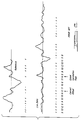
- FIG. 1 comprises waveforms and graphs helpful in understanding the general correlation function of the prior art;
- FIG. 2 similarly consists of waveforms and associated indicia helpful in understanding problems associated with prior art correlators when the live image is relatively bland;
- FIG. 3 is similar to FIG. 2 except that it illustrates the, improvement provided by way of the present invention;
- FIG. 4 is a functional block diagram of hardware for carrying out the teachings of the preferred embodiment of this invention; and
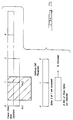
- FIG. 5 is useful in understanding the accession of correlation video from the framestores in the convolution process.
- Almost all correlators work on the premise that the reference image forms a subimage of a larger image called the live image. It is the function of the correlator to locate the portion of the live image which most nearly resembles the reference image. The correlator performs this function by successively superimposing the reference image on the live image with different offsets and computing a measure of similarity at each offset. The similarity measure is called the correlation function. The position of the global maximum of the correlation function yields a best estimate of the offset between the reference image and the live image.
- The bilevel correlation function is developed by accumulating the number of pixels with coincident polarity between the two images as shown in FIG. 1. Note that each pixel is used in the matching process and assigned equal weight. In those pixels where the signal magnitude is smaller than the noise, the polarity assigned to the pixel is determined by the polarity of the noise. These pixels are equally likely to- be positive or negative in polarity. Since the noise is independent from image to image, the noise dominated reference pixels are as likely to match or mismatch the corresponding pixels in the live image. Statistically, these pixels do not contribute to the magnitude of the correlation peak but increase the variance or the fluctuation of the peak magnitude. In bland scenes where the bulk of the reference pixels are noise dominated as shown in FIG. 2, the fluctuations of the peak magnitude can be so large relative to the mean peak that the correlation function's peak position no longer indicates the true offset between the two images.
- The maskable bilevel correlator of the present invention gets around the bland scene problem in a conceptually very simple manner. It reasons that since the noise dominated pixels do not contribute toward enhancing the magnitude of the correlation peak but increases its statistical fluctuation, they degrade the correlator's ability to correlate. Therefore, they must be excluded from the correlation process. Instead of using every pixel in the reference image in the correlation process, it ignores the noise dominated pixels. It does so by computing a pair of thresholds that is placed at kσ about the mean gradient amplitude of the input scene. (k is a constant typically in the range of 1 to 2 and σ is the standard deviation of the noise in the image). Those reference image pixels with magnitude between the threshold pairs have low signal to noise ratio and are masked off. Reference image pixels with magnitude outside of the region bounded by the threshold pair have good signal to noise ratio and are unmasked. Functionally, only unmasked pixels are used in the correlation process.
- The process of masking is illustrated in FIG. 3 where a "0" designates a pixel which has been masked off. In the correlation process the masked pixels are ignored. The ignoring of the masked pixels is accomplished by designating each pixel with a mask bit and a polarity bit. The polarity bit designates the polarity of the polarity. The mask bit takes on the value "0" for masked pixels and the value "1" for unmasked pixels. In the convolution process the polarity bits are logically compared using "exclusive nor" as with the bilevel correlator. The output of the exclusive nor is a "1" for polarity coincidence and a "0" for the lack of coincidence. The output of the "exclusive nor" is then logically "ANDed" with the mask bit for the reference pixel. For a pixel with mask bit "0", the output of the "AND" function will always be a "0" independent of the polarity coincidence of the pixel pair being compared. When the mask bit is a "1", the output is a "1" when the polarities coincide. FIG. 3 illustrates the correlation function obtained with the maskable bilevel correlator using the same waveform as FIG. 2. Note that the bilevel correlation peak in FIG. 2 indicated the wrong offset whereas the maskable bilevel correlator of FIG. 3 yields the correct result. By virtue of the masking feature, the maskable bilevel correlator is able to push the operational limit of the correlator to scenes that are too bland for the bilevel correlator to work.
- A second benefit of the maskable bilevel correlator is its ability to pick off portions of an image that are rich in details and hence are good reference images. The mask bit tags each pixel according to its signal to noise ratio (i.e., those with mask bit value "1" have good signal to noise ratio whereas those with value "0" have low signal to noise ratio). Correlation performance generally improves monotonically with the number of signal dominated pixels used in the reference area. For most practical correlators used for vehicle guidance the reference images are extracted from a "live" image and correlated against subsequent images in a bootstrap manner. The size of reference cell areas is small compared to the dimensions of the live image from which it is extracted. Typically the reference image may be 1% to 2% of the size of the live image. Thus there is a degree of freedom in terms of where the live image is scanned by the reference cell. At each pixel the density of unmasked pixels is computed and stored in a RAM. Locations with the highest unmasked pixel density represent good reference areas.
- A third usage of the maskable bilevel correlator is the determination of "clutterness" of the scene for use in multimode signal processors. In many applications the signal processing algorithm is adaptive on the basis of scene content. The number of unmasked pixels in the image provides a measure of the "clutterness" of the scene. A high density of unmasked pixels globally indicates that the scene has a high density of large spatial gradients. This condition implies that the scene is spatially inhomogeneous with large variations in intensity and is therefore "cluttered". It also indicates the scene is highly correlatable. This knowledge of scene "clutterness" can be used as an input for the adaptive selection of signal processing algorithms.
- The maskable bilevel correlator method of this invention can be implemented in hardware in many ways. The selection described here was chosen to yield maximum flexibility in current system applications.
- One
such correlator system 10 is shown in FIG. 4. It consists of the framestore anddata stacking network 12, the framestore address generator 14, thedata selector 16, the convolver andsummer 18, thescratch pad RAM 20, the scratchpad address generator 22, thearithmetical unit 24, and timing andcontrol circuits 26. The functions of these subsystems are described below. - The heart of the correlator is the bit comparison function (convolver) 18. This function had been previously described as an EXCLUSIVE-NOR of the live and reference images followed by the 'AND' of this term with the mask bit of the reference image. Using DeMorgan's theorem, any of the inputs coupled with the EXCLUSIVE-NOR and 'AND' function may be changed to other combinations of logical elements to yield identical outputs. This change of logical elements allows us to take advantage of the technology available today. The mechanization selected for the breadboard system with the 'EXCLUSIVE-OR' of the live and reference images via
gate 17 followed by the 'NOR' of this term with the mask bit of the reference inverted viagate 19 andinverter 21. The output of this circuit yields the same results as the method described earlier, a '1' if the live and reference matched in polarity with the reference unmasked and a '0' otherwise. - A single bit comparison, while hardware frugal, limits the ability of the convolver to correlate large references with large search ranges due to time constraints. In our case, operation is at 60 Hz with multiple references. To accomplish the higher throughput, the reference is divided into cells containing 8 pixels horizontally and 8 lines vertically (covering 64 pixel locations in area). The eight by eight format was chosen to make use of the by 8-bit data width of available RAM memory devices. The bit convolver is expanded to accept 64 live pixels, 64 reference pixels and 64 mask bits.
- Video from preprocessing
circuit 30 is comprised of a polarity bit and a mask bit which has been assigned to each pixel position according to the aforementioned differentiating and thresholding process. Briefly, thepreprocessing circuit 30 includes suitable means such as known analog to digital (A/D) converters to digitize the raw analog signal from the sensor into a digital greylevel image. A gradient processor operates on this digital greylevel image to generate a gradient image where each pixel value is a function of the spatial gradient or difference between neighboring pixel values. The present invention preferably operates on such gradient images to generate the polarity and mask bits for each pixel position. If the gradient signal value at a given pixel position is above or below a positive or negative threshold kσ, respectively, the mask bit is assigned a digital one value.- Otherwise, the mask bit is given a digital zero value for that pixel position. The polarity bit is a function of the polarity of the amplitude of the gradient signal at a given pixel position. If the amplitude is positive then the polarity bit will be assigned a digital value of one whereas if the gradient signal value is negative, the polarity bit at this pixel position will be assigned a digital value of zero. In this embodiment, the reference image is derived by undergoing this differentiation and thresholding process and storing the resultant data in thescratch pad RAM 20 where it can be later compared to live images consisting of subsequently similarly generated image data. - The similarly preprocessed "live" signal (mask plus polarity) is stored in a framestore RAM 32 via
shift register 34. A framestore is used to capture the image so that multiple cells may be convolved throughout the image with one convolver in a time sequenced manner. Real time convolution of video without the framestore would generally require one convolver for each cell within the reference or would require a single convolver with nonoverlapped reference search locations. A dual framestore is used in a ping-pong fashion to yield real time operation. One set of framestore memories is being loaded by thepreprocessor 30 while the second set is used by thecorrelator 10.Shift register 34 at the input to the framestore RAM 32 is used to stack the data into 8-bit words for parallel access by the convolver. - The
correlator 10 extracts data from the framestore RAM 32 with addresses output by theframestore address generator 14 and passes that data throughselector 16. Theaddress generator 14 is comprised of an X and Y address (viacounters 36 and 38, respectively) representing the horizontal and vertical direction of scan of the references. The address in the X axis is a 'bit location', the lower three address lines are used by the data selector to align the input data to the convolver. The Y address is the video line location. Two consecutive 8-bit data words are accessed then mixed to align them to the proper bit location. FIG. 5 shows the process functionally. - The
data selector 16 is comprised of tworegisters mux selector circuit 39. As shown in FIG. 5 theselector 16 requires two accesses to the framestore to obtain one 8 bit byte which is then output to the convolver. On the first access to the framestore, the 8 bit data is saved inregister 33. The data from the second access is saved inregister 35. The two registers hold the data stable while theselector mux 39 aligns them to the proper bit locations. During this time the next access is initiated to the framestore. -
Mux 41 is used to control the ping-pong framestores RAM 32. There is one set of multiplexers for each of the two memories that comprise the framestore. The multiplexers select which addresses and control lines are input to each of the framestore memories. During any single field of video,mux 41 will select theframestore address generator 14 to one of the framestore memories and the video address input to the other. This will alternate each field yielding the required ping-pong operation of the framestore memory. - The 8 bits of data selected from the framestore RAM 32 are input to the convolver's live storage registers. This is mechanized as eight 8-bit shift registers (one of which is shown labelled as 40). These registers are used to stack the input data into the 8 x 8 format of a cell and present the 64 pixels to the convolver. This section also includes a 64-
bit reference register 42 and a 64-bit mask register 44 each loaded from the scratch pad RAM 46 as four 16-bit words. These three 64-bit registers are the input to the convolver bit comparisons. The 64-bit comparisons are accomplished by theconvolver gates network 23 follows the convolver to add the number of matches (1′s) from the bit comparison and provide an output which is a function of the correlation between the thresholded live and reference images. In particular, thesummer 23 will peak when the live image is correlated with the reference image (see, e.g., FIG. 1). - The convolver summing network feeds the
arithmetic unit 24 which includesmultiplexer 43, register 45, andarithmetic logic unit 47. The arithmetic unit is used to accumulate correlation surfaces, accumulate unmasked pixel surfaces and add or subtract partial correlation surfaces. - The
scratch pad RAM 20 is the storage location for all variables and data required by the correlation hardware. These data are defined as follows: - 1. Reference storage - multiple 8 x 8 reference cells are packed into consecutive memory locations.
- 2. Mask storage - multiple 8 x 8 mask cells corresponding to each of the references are stored in the same format as their associated references.
- 3. Surface store - two dimensional arrays of convolution sums representing the correlation surface of a cell or multiple cells.
- 4. Correlatable regions - two dimensional arrays representing the sum of unmasked pixels at each possible reference location.
- 5. Instruction store - instruction list and constants defining the sequence of operation of the correlator, number of cells, cell placement, search ranges and address pointing to data storage areas.
- The scratch
pad address generator 22 includesRAM memory 49,multiplexer 51,address register 53, andincrementer 55. The address generator is responsible for maintaining current addresses for all processes presently taking place in the correlator.RAM 49 is 16 x 16 word storage devices which contains address pointers to scratch pad memory locations.RAM 49 data is as follows: - 0 - Program counter
- 1 - Convolve enable table address
- 2 - Peak table address
- 3 - Search size table address
- 4 - Cell location table address
- 5 - Cell masks address
- 6 - Cell references address
- 7 - Accumulated mask sum table address
- 8 - Surface table address
- 9 - Refresh enable table address
- 10 - Refresh table address
- 11 - Temporary address
- 12 - Temporary address
- 13 - Temporary address
- 14 - Temporary address
- 15 - Temporary address
- The first location in
RAM 49 is the address to the next instruction to be executed by the correlator.Locations 1 through 10 contain the addresses to the required information used during a correlation instruction. These addresses are incremented byincrementer 55 so they always point to the next address location for valid data. Locations 11-15 are used as temporary address locations by the data manipulation instructions for adding, subtracting, moving or clearing correlation surface data.Mux 51 selects the data to be input toRAM 49. When updating the RAM for a new correlation,Mux 51 selects data from thescratch pad RAM 20. While executing the correlation instruction,mux 51 selects the data fromincrementer 55 for local updating of parameter addresses.Address register 53 maintains a stable address to thescratch pad RAM 20 whileRAM 49 is updated with the newly incremented value fromincrementer 55. - Automatic correlatable area selection is accomplished by accumulating a surface which is comprised of the number of unmasked pixels at any cell or region location in the field. A large number of unmasked pixel corresponds to an area rich with spatial gradients. A peak detection instruction implemented in the correlator is used to find the 'n' highest peaks within any locally specified region (e.g., quadrants of the field of view). The coordinates from the peak detector indicate the most correlatable regions.
- Referring to FIG. 4, this function is mechanized by performing a correlation on the mask bits of the live scene. RAM 32 is selected to output mask bits (in the same manner as required to update cell reference masks). The
data selector 16 aligns data as previously described and outputs it to the convolver andsummer 10.Register 40 stacks the mask bits into the 8 x 8 cell configuration for the 64 bit convolution. For mask accumulation, thereference register 42 is cleared to zero allowing the mask bits to be compared against zero ('0' being the state of an unmasked pixel) and themask register 44 is cleared to zero representing no masked pixels in the convolution. The output ofgate 19 is a '1' for every unmasked pixel and the output ofsummer 23 is the number of unmasked pixels within an 8 x 8 pixel region or cell. If the 8 x 8 region is swept over the entire video field,arithmetic unit 24 will build a two dimensional surface of unmasked pixel values indicating correlatability within the field of view.
Claims (8)
- In a method of correlating two input signals associated with a live image and a reference image, the improvement which includes the steps of:a) processing the reference image to provide a polarity bit and a mask bit for each pixel position therein, the value of the mask bit being one digital state defining an off condition if the amplitude of the signal falls between two preselected threshold levels and being of an opposite state defining an on condition if the amplitude is outside of the threshold levels, the value of the polarity bit being one digital state if the amplitude is positive and being of an opposite state if the amplitude is negative at that pixel position;b) processing the live image so as to provide a polarity bit for each pixel position therein, the value of the polarity bit being one digital state if the amplitude is positive and being of an opposite state if the amplitude is negative at that pixel position; andc) using the processed reference and live signals to generate a correlation output sum by accumulating the number of matches between the polarity bits of the processed reference and live signals whereby those pixels with associated mask bit indicating the off condition are prevented from being included in the correlation output sum.
- The method of claim 1 wherein step b) includes measuring the density of mask bits defining the on condition; and
using those regions in the reference image with the highest density of such mask bits to correlate against the live image. - The method of claim 1 or 2 wherein the polarity bits are gated in an EXCLUSIVE-OR gate.
- The method of claim 3 wherein the output of the EXCLUSIVE-OR gate is coupled to an input of a NOR gate, another input of the NOR gate being coupled for receipt of the mask bit of the reference signal.
- The method of claim 4 wherein the output of the NOR gate is coupled to a summer for summing the number of logical ones from the NOR gate, the output of the summer providing an output which will peak when the live image is correlated with the reference image.
- Apparatus (10) for correlating two input signals associated with a live image and a reference image, comprising:
means for processing the reference image to provide a polarity bit and a mask bit for each pixel position therein, the value of the mask bit being one digital state defining an off condition if the amplitude of the signal falls between two preselected threshold levels and being of an opposite state defining an on condition if the amplitude is outside of the threshold levels, the value of the polarity bit being one digital state if the amplitude is positive and being of an opposite state if the amplitude is negative at that pixel position;
means (30) for processing the live image signal to provide a polarity bit for each pixel position therein the value of the polarity bit being one digital state if the amplitude is positive and being of an opposite state if the amplitude is negative at that pixel position; and
means (18) for generating a correlation output sum from the processed reference and live signals by accumulating the number of matches between the polarity bits of the processed reference and live signals whereby those pixels with associated mask bit indicating the off condition are prevented from being included in the correlation output sum. - Apparatus according to claim 6, which further comprises:
polarity bit storage means (20; 42) for storing the polarity bits of the reference image;
mask bit storage means (20; 44) for the mask bits of the reference image. - Apparatus according to claim 6 or 7, comprising:
an EXCLUSIVE-OR gate (17) having one input connected to the reference polarity bit storage means and another input connected for receipt of polarity bits of the live image;
a logical NOR gate (19) having an input coupled to the output of the EXCLUSIVE-OR gate and an input coupled through an inverter (21) to the reference mask bit storage means; and
summing means (23) coupled to the output of the NOR gate for accumulating logical ones therefrom which indicate the number of unmasked polarity bit matches between the live and reference images.
Applications Claiming Priority (3)
| Application Number | Priority Date | Filing Date | Title |
|---|---|---|---|
| US229407 | 1988-08-08 | ||
| US07/229,407 US5020113A (en) | 1988-08-08 | 1988-08-08 | Maskable bilevel correlators |
| PCT/US1989/002875 WO1990001744A1 (en) | 1988-08-08 | 1989-07-03 | Maskable bilevel correlator |
Publications (2)
| Publication Number | Publication Date |
|---|---|
| EP0386181A1 EP0386181A1 (en) | 1990-09-12 |
| EP0386181B1 true EP0386181B1 (en) | 1994-09-14 |
Family
ID=22861118
Family Applications (1)
| Application Number | Title | Priority Date | Filing Date |
|---|---|---|---|
| EP89907913A Expired - Lifetime EP0386181B1 (en) | 1988-08-08 | 1989-07-03 | Maskable bilevel correlator |
Country Status (12)
| Country | Link |
|---|---|
| US (1) | US5020113A (en) |
| EP (1) | EP0386181B1 (en) |
| JP (1) | JP2552010B2 (en) |
| KR (1) | KR930002338B1 (en) |
| AU (1) | AU616986B2 (en) |
| CA (1) | CA1316264C (en) |
| DE (1) | DE68918263T2 (en) |
| ES (1) | ES2016050A6 (en) |
| IL (1) | IL90984A (en) |
| NO (1) | NO177472C (en) |
| TR (1) | TR24992A (en) |
| WO (1) | WO1990001744A1 (en) |
Families Citing this family (25)
| Publication number | Priority date | Publication date | Assignee | Title |
|---|---|---|---|---|
| US4958378A (en) * | 1989-04-26 | 1990-09-18 | Sun Microsystems, Inc. | Method and apparatus for detecting changes in raster data |
| US5239496A (en) * | 1989-12-27 | 1993-08-24 | Nynex Science & Technology, Inc. | Digital parallel correlator |
| DE4009610A1 (en) * | 1990-03-26 | 1991-10-02 | Philips Patentverwaltung | CIRCUIT ARRANGEMENT FOR DETERMINING THE POSITION OF EXTREMAL VALUES OF A SIMILAR FUNCTION |
| US5261010A (en) * | 1991-09-27 | 1993-11-09 | Hughes Aircraft Comany | Automatic mask threshold |
| US7242988B1 (en) | 1991-12-23 | 2007-07-10 | Linda Irene Hoffberg | Adaptive pattern recognition based controller apparatus and method and human-factored interface therefore |
| US6418424B1 (en) | 1991-12-23 | 2002-07-09 | Steven M. Hoffberg | Ergonomic man-machine interface incorporating adaptive pattern recognition based control system |
| US6400996B1 (en) | 1999-02-01 | 2002-06-04 | Steven M. Hoffberg | Adaptive pattern recognition based control system and method |
| US10361802B1 (en) | 1999-02-01 | 2019-07-23 | Blanding Hovenweep, Llc | Adaptive pattern recognition based control system and method |
| US6850252B1 (en) | 1999-10-05 | 2005-02-01 | Steven M. Hoffberg | Intelligent electronic appliance system and method |
| US5903454A (en) | 1991-12-23 | 1999-05-11 | Hoffberg; Linda Irene | Human-factored interface corporating adaptive pattern recognition based controller apparatus |
| US8352400B2 (en) | 1991-12-23 | 2013-01-08 | Hoffberg Steven M | Adaptive pattern recognition based controller apparatus and method and human-factored interface therefore |
| US5317644A (en) * | 1992-06-16 | 1994-05-31 | Mcgill University | Method for the enhancement of cell images |
| US5588067A (en) * | 1993-02-19 | 1996-12-24 | Peterson; Fred M. | Motion detection and image acquisition apparatus and method of detecting the motion of and acquiring an image of an object |
| CA2135240A1 (en) * | 1993-12-01 | 1995-06-02 | James F. Frazier | Automated license plate locator and reader |
| US5917960A (en) * | 1996-01-31 | 1999-06-29 | Canon Kabushiki Kaisha | Image correlator, an image processing apparatus using the same, and a signal adder used in the image correlator |
| JP3434979B2 (en) | 1996-07-23 | 2003-08-11 | 富士通株式会社 | Local area image tracking device |
| KR100255648B1 (en) * | 1997-10-10 | 2000-05-01 | 윤종용 | Video motion detection apparatus and method by gradient pattern matching |
| US6088488A (en) * | 1998-04-17 | 2000-07-11 | General Electric Company | Vascular imaging with adaptive averaging |
| US7966078B2 (en) | 1999-02-01 | 2011-06-21 | Steven Hoffberg | Network media appliance system and method |
| WO2004049240A1 (en) * | 2002-11-28 | 2004-06-10 | Nokia Corporation | Method and device for determining and outputting the similarity between two data strings |
| US7359565B2 (en) * | 2004-05-03 | 2008-04-15 | International Business Machines Corporation | Method of filtering pixels in a video encoding process |
| US7783694B2 (en) * | 2006-05-12 | 2010-08-24 | International Business Machines Corporation | Identification of relevant metrics |
| US9813721B2 (en) | 2014-11-20 | 2017-11-07 | Getgo, Inc. | Layer-based video encoding |
| US10237559B2 (en) | 2014-11-20 | 2019-03-19 | Getgo, Inc. | Layer-based video decoding |
| EP3035204B1 (en) * | 2014-12-19 | 2018-08-15 | Intel Corporation | Storage device and method for performing convolution operations |
Family Cites Families (18)
| Publication number | Priority date | Publication date | Assignee | Title |
|---|---|---|---|---|
| US2541256A (en) * | 1946-01-22 | 1951-02-13 | Manning Maxwell & Moore Inc | Pressure cooker gauge |
| FR949337A (en) * | 1946-08-28 | 1949-08-26 | Nat Pressure Cooker Co | Manometer |
| US3597083A (en) * | 1969-04-16 | 1971-08-03 | Itek Corp | Method and apparatus for detecting registration between multiple images |
| DE2510808C2 (en) * | 1975-03-12 | 1982-09-09 | Silit-Werke Gmbh & Co Kg, 7940 Riedlingen | Pressure cooker |
| US4244029A (en) * | 1977-12-12 | 1981-01-06 | Goodyear Aerospace Corporation | Digital video correlator |
| FR2445714A1 (en) * | 1979-01-03 | 1980-08-01 | Seb Sa | Pressure cooker valve assembly - has housing with cylindrical cavity in which is outlet and valve body, with duct |
| EP0005918B1 (en) * | 1979-05-09 | 1983-05-04 | Hughes Aircraft Company | Scene tracker system |
| DE3002204C2 (en) * | 1980-01-22 | 1986-05-28 | Württembergische Metallwarenfabrik, 7340 Geislingen | Pressure cooker |
| DE3108017C2 (en) * | 1981-03-03 | 1988-07-07 | Fissler Gmbh, 6580 Idar-Oberstein | Pressure display device on a pressure cooker |
| US4475238A (en) * | 1982-04-05 | 1984-10-02 | Everhart Glenn C | Magnetoresistive image correlation device |
| DE3486194T2 (en) * | 1983-06-03 | 1993-11-18 | Fondazione Pro Juventute Don C | Modular system for real-time processing of a TV display, particularly useful for coordinate detection of objects of known shape and method for using this system for X-rays. |
| JPS60157375A (en) * | 1983-12-21 | 1985-08-17 | Fuji Xerox Co Ltd | Halftone expressing system |
| US4750144A (en) * | 1985-12-31 | 1988-06-07 | The United States Of America As Represented By The Administrator Of The National Aeronautics And Space Administration | Real time pipelined system for forming the sum of products in the processing of video data |
| US4864629A (en) * | 1985-12-31 | 1989-09-05 | Schlumberger Technologies, Inc. | Image correlation system |
| JPS63228881A (en) * | 1987-03-17 | 1988-09-22 | Minolta Camera Co Ltd | Image processing system |
| AU612503B2 (en) * | 1988-08-08 | 1991-07-11 | Hughes Aircraft Company | Distinguishing a moving object from a noisy background |
| US4959714A (en) * | 1988-08-08 | 1990-09-25 | Hughes Aircraft Company | Segmentation method for terminal aimpoint determination on moving objects and apparatus therefor |
| CA1320586C (en) * | 1988-12-20 | 1993-07-20 | Chris Malachowsky | Method and apparatus for sorting line segments for display and manipulation by a computer system |
-
1988
- 1988-08-08 US US07/229,407 patent/US5020113A/en not_active Expired - Fee Related
-
1989
- 1989-07-03 DE DE68918263T patent/DE68918263T2/en not_active Expired - Lifetime
- 1989-07-03 JP JP1507445A patent/JP2552010B2/en not_active Expired - Lifetime
- 1989-07-03 WO PCT/US1989/002875 patent/WO1990001744A1/en not_active Ceased
- 1989-07-03 AU AU38510/89A patent/AU616986B2/en not_active Ceased
- 1989-07-03 EP EP89907913A patent/EP0386181B1/en not_active Expired - Lifetime
- 1989-07-14 IL IL90984A patent/IL90984A/en unknown
- 1989-07-18 CA CA000606008A patent/CA1316264C/en not_active Expired - Fee Related
- 1989-08-03 ES ES8902763A patent/ES2016050A6/en not_active Expired - Fee Related
- 1989-08-08 TR TR89/0600A patent/TR24992A/en unknown
-
1990
- 1990-04-04 NO NO901531A patent/NO177472C/en not_active IP Right Cessation
- 1990-04-06 KR KR9070720A patent/KR930002338B1/en not_active Expired - Lifetime
Also Published As
| Publication number | Publication date |
|---|---|
| CA1316264C (en) | 1993-04-13 |
| IL90984A (en) | 1993-01-31 |
| NO901531D0 (en) | 1990-04-04 |
| KR930002338B1 (en) | 1993-03-29 |
| AU616986B2 (en) | 1991-11-14 |
| JPH03501901A (en) | 1991-04-25 |
| US5020113A (en) | 1991-05-28 |
| ES2016050A6 (en) | 1990-10-01 |
| DE68918263D1 (en) | 1994-10-20 |
| AU3851089A (en) | 1990-03-05 |
| NO901531L (en) | 1990-04-04 |
| DE68918263T2 (en) | 1995-04-13 |
| NO177472C (en) | 1995-09-20 |
| EP0386181A1 (en) | 1990-09-12 |
| KR900702466A (en) | 1990-12-07 |
| IL90984A0 (en) | 1990-02-09 |
| NO177472B (en) | 1995-06-12 |
| JP2552010B2 (en) | 1996-11-06 |
| TR24992A (en) | 1992-08-21 |
| WO1990001744A1 (en) | 1990-02-22 |
Similar Documents
| Publication | Publication Date | Title |
|---|---|---|
| US5020113A (en) | Maskable bilevel correlators | |
| US4220967A (en) | Scene tracker using multiple independent correlators | |
| US4310827A (en) | Device for extracting a density as one of pattern features for each feature point of a streaked pattern | |
| US4754493A (en) | Automatic recognition and guidance arrangements | |
| EP0005918B1 (en) | Scene tracker system | |
| US4742552A (en) | Vector image processing system | |
| US6134340A (en) | Fingerprint feature correlator | |
| US4409661A (en) | Aimpoint selection processor | |
| US20060120590A1 (en) | Automatic scene correlation and identification | |
| US4205302A (en) | Word recognizing system | |
| US4433438A (en) | Sobel edge extraction circuit for image processing | |
| US5321772A (en) | Digital image processor | |
| US3982227A (en) | Pattern recognition machine for analyzing line orientation | |
| US4783831A (en) | Method for producing a standard pattern for pattern matching | |
| EP0495182A2 (en) | Constellation matching system and method | |
| EP0001808A2 (en) | Method and apparatus for binary word recognition | |
| Smith et al. | On the detection of target trajectories in a multi target environment | |
| JPS5582380A (en) | Pattern processing unit | |
| Masaki | Parallel/pipelined processor dedicated to visual recognition | |
| GB2067744A (en) | Digital Video Correlator | |
| JPS623475B2 (en) | ||
| GB2330028A (en) | Target tracking method | |
| Długosz et al. | A Method Supporting Hardware Implementation of Vector Quantization Module in HoG Algorithm | |
| JPS55138603A (en) | Detecting system of pattern position | |
| JPH0498580A (en) | Method and device for pattern recognition |
Legal Events
| Date | Code | Title | Description |
|---|---|---|---|
| PUAI | Public reference made under article 153(3) epc to a published international application that has entered the european phase |
Free format text: ORIGINAL CODE: 0009012 |
|
| 17P | Request for examination filed |
Effective date: 19900222 |
|
| AK | Designated contracting states |
Kind code of ref document: A1 Designated state(s): CH DE FR GB IT LI NL SE |
|
| 17Q | First examination report despatched |
Effective date: 19930525 |
|
| GRAA | (expected) grant |
Free format text: ORIGINAL CODE: 0009210 |
|
| AK | Designated contracting states |
Kind code of ref document: B1 Designated state(s): CH DE FR GB IT LI NL SE |
|
| REF | Corresponds to: |
Ref document number: 68918263 Country of ref document: DE Date of ref document: 19941020 |
|
| ET | Fr: translation filed | ||
| ITF | It: translation for a ep patent filed | ||
| EAL | Se: european patent in force in sweden |
Ref document number: 89907913.1 |
|
| PLBE | No opposition filed within time limit |
Free format text: ORIGINAL CODE: 0009261 |
|
| STAA | Information on the status of an ep patent application or granted ep patent |
Free format text: STATUS: NO OPPOSITION FILED WITHIN TIME LIMIT |
|
| 26N | No opposition filed | ||
| PGFP | Annual fee paid to national office [announced via postgrant information from national office to epo] |
Ref country code: SE Payment date: 19960614 Year of fee payment: 8 |
|
| PGFP | Annual fee paid to national office [announced via postgrant information from national office to epo] |
Ref country code: NL Payment date: 19960620 Year of fee payment: 8 |
|
| PG25 | Lapsed in a contracting state [announced via postgrant information from national office to epo] |
Ref country code: SE Effective date: 19970704 |
|
| PG25 | Lapsed in a contracting state [announced via postgrant information from national office to epo] |
Ref country code: NL Free format text: LAPSE BECAUSE OF NON-PAYMENT OF DUE FEES Effective date: 19980201 |
|
| NLV4 | Nl: lapsed or anulled due to non-payment of the annual fee |
Effective date: 19980201 |
|
| EUG | Se: european patent has lapsed |
Ref document number: 89907913.1 |
|
| REG | Reference to a national code |
Ref country code: GB Ref legal event code: 732E |
|
| REG | Reference to a national code |
Ref country code: FR Ref legal event code: CA Ref country code: FR Ref legal event code: TP Ref country code: FR Ref legal event code: CD |
|
| REG | Reference to a national code |
Ref country code: GB Ref legal event code: IF02 |
|
| PG25 | Lapsed in a contracting state [announced via postgrant information from national office to epo] |
Ref country code: IT Free format text: LAPSE BECAUSE OF NON-PAYMENT OF DUE FEES;WARNING: LAPSES OF ITALIAN PATENTS WITH EFFECTIVE DATE BEFORE 2007 MAY HAVE OCCURRED AT ANY TIME BEFORE 2007. THE CORRECT EFFECTIVE DATE MAY BE DIFFERENT FROM THE ONE RECORDED. Effective date: 20050703 |
|
| REG | Reference to a national code |
Ref country code: CH Ref legal event code: PCAR Free format text: ISLER & PEDRAZZINI AG;POSTFACH 1772;8027 ZUERICH (CH) |
|
| PGFP | Annual fee paid to national office [announced via postgrant information from national office to epo] |
Ref country code: CH Payment date: 20080620 Year of fee payment: 20 |
|
| PGFP | Annual fee paid to national office [announced via postgrant information from national office to epo] |
Ref country code: DE Payment date: 20080623 Year of fee payment: 20 |
|
| PGFP | Annual fee paid to national office [announced via postgrant information from national office to epo] |
Ref country code: FR Payment date: 20080613 Year of fee payment: 20 |
|
| PGFP | Annual fee paid to national office [announced via postgrant information from national office to epo] |
Ref country code: GB Payment date: 20080620 Year of fee payment: 20 |
|
| REG | Reference to a national code |
Ref country code: CH Ref legal event code: PL |
|
| REG | Reference to a national code |
Ref country code: GB Ref legal event code: PE20 Expiry date: 20090702 |
|
| PG25 | Lapsed in a contracting state [announced via postgrant information from national office to epo] |
Ref country code: GB Free format text: LAPSE BECAUSE OF EXPIRATION OF PROTECTION Effective date: 20090702 |