EP0385055A1 - Storage box for screw driver bits - Google Patents
Storage box for screw driver bits Download PDFInfo
- Publication number
- EP0385055A1 EP0385055A1 EP90100057A EP90100057A EP0385055A1 EP 0385055 A1 EP0385055 A1 EP 0385055A1 EP 90100057 A EP90100057 A EP 90100057A EP 90100057 A EP90100057 A EP 90100057A EP 0385055 A1 EP0385055 A1 EP 0385055A1
- Authority
- EP
- European Patent Office
- Prior art keywords
- storage box
- box according
- compartment
- compartments
- screwdriver
- Prior art date
- Legal status (The legal status is an assumption and is not a legal conclusion. Google has not performed a legal analysis and makes no representation as to the accuracy of the status listed.)
- Granted
Links
Images


Classifications
-
- B—PERFORMING OPERATIONS; TRANSPORTING
- B25—HAND TOOLS; PORTABLE POWER-DRIVEN TOOLS; MANIPULATORS
- B25B—TOOLS OR BENCH DEVICES NOT OTHERWISE PROVIDED FOR, FOR FASTENING, CONNECTING, DISENGAGING OR HOLDING
- B25B13/00—Spanners; Wrenches
- B25B13/56—Spanner sets
-
- B—PERFORMING OPERATIONS; TRANSPORTING
- B25—HAND TOOLS; PORTABLE POWER-DRIVEN TOOLS; MANIPULATORS
- B25G—HANDLES FOR HAND IMPLEMENTS
- B25G1/00—Handle constructions
- B25G1/08—Handle constructions with provision for storing tool elements
- B25G1/085—Handle constructions with provision for storing tool elements for screwdrivers, wrenches or spanners
-
- B—PERFORMING OPERATIONS; TRANSPORTING
- B25—HAND TOOLS; PORTABLE POWER-DRIVEN TOOLS; MANIPULATORS
- B25H—WORKSHOP EQUIPMENT, e.g. FOR MARKING-OUT WORK; STORAGE MEANS FOR WORKSHOPS
- B25H3/00—Storage means or arrangements for workshops facilitating access to, or handling of, work tools or instruments
- B25H3/003—Holders for drill bits or the like
Definitions
- the invention is based on a storage box which is provided for storing screwdriver bits and has the features of the preamble of claim 1.
- a generic storage box which has the shape of a can.
- the approximately disc-shaped lower part is overlapped by a bowl-shaped cover.
- the lid is rotatably and loosely connected to the lower part.
- compartments In the lower part there are several compartments in parallel, which serve to hold the screwdriver bits and which open in the direction of the peripheral surface of the disk-shaped lower part.
- the compartments have a square cross section and are also completely open in the direction of the lid, which is made of transparent material. Opposite the removal opening of the compartments located on the peripheral surface of the lower part is the shelf, which prevents the inserts from falling too deep.
- compartments there is another compartment in the lower part for receiving the coupling shaft, which extends at right angles to the compartments for the screwdriver bits and penetrates the outer peripheral surface of the lower part on at least one side.
- the screwdriver bits or the magnetic shaft are removed by aligning the cover with an opening in its circumference in alignment with the desired compartment. Then the screwdriver insert or the magnetic shaft can be poured out through the now opened compartment.
- the lid With this form of storage box, the lid must be transparent so that the user can select the correct compartment with the desired screwdriver bit. For this reason, he can only determine if the lid is twisted far enough after removing or refilling the screwdriver bit so that the removal openings of all compartments are closed. Otherwise, screwdriver bits could accidentally fall out and get lost.
- this receptacle is solved by the storage box with the features of claim 1.
- the storage box can be opened like a cigar box and the user can access all the tools in it at the same time.
- the closed position of the lid is easily recognizable, making it impossible for one of the storage compartments in the box to be accidentally left unlocked.
- the tools are all safely stored with the lid closed and cannot fall out.
- the user-friendliness of the new storage box also improves the additional hexagon opening that opens outwards and into which the coupling shaft with its hexagonal end can be inserted.
- the storage box can be used as a makeshift screwdriver that can be easily stored in your pocket.
- the hinge is a film hinge, the base body, the film hinge and the cover preferably being integrally connected to one another. Unnecessary dead space within the storage box between the individual compartments is avoided if it has an approximately cuboid shape. It is then only Side contains a slot, the width of which is smaller than the diameter of the clamping shaft of the screwdriver bit.
- the slot preferably has a width which corresponds to the width of one of the hexagonal surfaces.
- retaining springs can be provided in the compartments, which prestress the inserted screwdriver bits in the direction of the slot. As a result, the screwdriver bits are held in the compartments by friction and cannot fall out even when the lid is open and the removal openings are pointing downwards. As with a dispenser, they can be pushed out of the compartment on the surface looking out through the slot.
- the retaining springs are tongue springs which, in order to further simplify production, are an integral part of the underside or the bottom of the lower part.
- the root of the tongue or leaf spring is located near the removal opening of the respective compartment, while the free part standing up from the floor lies in the direction of the bottom of the blind hole.
- the compartments for the screwdriver bits have the shape of flat tubs or channels. At its end lying towards the inside of the box, each tub is spanned by an arch, which is slit centrally in the longitudinal direction of the tub. This fixes the hexagonal end of the screwdriver bit in the tub.
- This embodiment has the advantage of the simpler injection mold and in addition, these partial arches are more robust and less sensitive to damage than tongue springs.
- the compartment for the coupling shaft is preferably arranged at right angles to the compartments of the screwdriver inserts, namely between the hinge and the bottom of the compartments.
- the storage box has an opening on one of its sides, which is adapted in cross-section and in size to the clamping shaft of the coupling shaft, it can be used as an emergency handle.
- This opening can be designed as a through opening and arranged in alignment with the receiving compartment for the coupling shaft, at the same time hold the coupling shaft frictionally when the cover is open.
- the minimum dimensions of the storage box are not increased in this way, because the through opening receives the clamping pin of the coupling shaft.
- the handling of the storage box is made considerably easier if it has a grip surface next to the lid, i.e. on the top a section that is not covered by the lid and is preferably flush with the lid when the lid is closed.
- This grip surface can be structured on the top and on the bottom of the storage box, for example by knobs or small recesses, in order to ensure a non-slip grip.
- the opening of the lid is considerably easier.
- opening the fingertip can penetrate a little into the gap to lift the lid. The aid of the fingernails is not necessary.
- a storage box 1 is illustrated in different handling positions, which serves to pick up several, in the example shown, six screwdriver blades or screwdriver bits 2, for example according to DIN 2126. These screwdriver bits are also called bits. Furthermore, an associated corresponding coupling shaft or magnet holder 3 can also be accommodated in the storage box 1.
- the storage box 1 has an approximately cuboid shape with two parallel and spaced flat sides 4 and 5, two parallel and spaced short narrow sides 6 and 7 and two also parallel and spaced long narrow sides 8 and 9.
- the long narrow sides 8 and 9 are, as can be seen from the figures, partially cylindrical, while the other two narrow sides 6 and 7, apart from a small chamfer, are essentially flat. In the area of the long narrow side 9, the storage box 1 is thickened to form a cylindrical bulge on the upper side for the reasons explained below.
- the storage box 1 consists of an approximately bowl-shaped lower part 11, on which a cover 12 is integrally formed by means of a film hinge 13. It is a single molded plastic part.
- the lid 12 together with a grip surface 14 forms the upper side 4 and in each case part of the two long narrow sides 8 and 9. In the closed state, the cover 12 is flush with the grip surface 14 and the cover 12 also sits smoothly and flush in the contour of the two narrow sides 8 and 9 continued.
- the film hinge 13 is located approximately half way up the long narrow side 9 and extends to it parallel, so that part of the narrow side 9 is part of the lower part 11 and the other part, based on the thickness, is part of the cover 12.
- the cover 12 On the side remote from the film hinge 13, the cover 12 is provided with an extension 15 following the contour of the storage box 1.
- This extension 15 forms part of the narrow side 8.
- the other part of the narrow side 8 is an edge 16 of the lower part which protrudes a little from below and ends at a straight edge 17.
- the slot 18 runs approximately along the center of the narrow side 8 between the gripping surface 14 and the narrow side 7.
- the grip surface 14 is the top or the bottom of a grip 19 lying next to the cover 12, in which the lower part 11 is solid.
- the upper flat side 4 or the lower flat side 5 is provided with a structure, for example in the form of small knobs 21, so that the gripping surface 14 is largely non-slip.
- the cover 12 and the lower part 11 together delimit a chamber 22 which extends within the lower part 11 between the inner sides of the two narrow sides 8 and 9 and the inner sides of the narrow side 7 and a corresponding wall 23 of the handle 19.
- the chamber 23 contains a plurality of compartments 24 for the screwdriver inserts 2, which are aligned in the exemplary embodiment shown, a total of six compartments 24 parallel to the narrow sides 6 and 7.
- Each of the compartments 24 is a blind hole-like structure, the bottom 25 of which is oriented in the direction of the film hinge 13 and the removal opening 26 in the direction of the narrow side 8.
- the compartments 24 are separated from one another by central webs 27, which are integrally connected to the inner surface of the underside 5.
- Each compartment 24 contains on its side facing the cover 12 a slot 28 which extends from the bottom 25 to the removal opening 26 and is also open at this point.
- the width of the slot 28 is dimensioned such that on the one hand the screwdriver bits 2 cannot pass through the slot 28, but on the other hand at least so far that they can protrude a little with their clamping shank 29 over a boundary surface 31 in which the slots 28 are located. Since the clamping shafts 29 are hexagonal, the width of the slot 28 is slightly larger than the width of each of the hexagonal surfaces.
- the boundary surface 31 runs parallel to the flat side 4, with a distance from this, which corresponds approximately to the thickness of the cover 12.
- each compartment 24 In order to hold the screwdriver bits 2 frictionally in each compartment 24 and to be able to push the corresponding side a little outwards through the slot 28, there is a leaf spring 32 in each compartment 24, which, starting from the inner surface of the cover 12 the opposite lower flat side 5 rises into the interior of the corresponding compartment 24, starting from the removal opening 26 in the direction of the bottom 25. This creates an approximately funnel-shaped structure, the greatest width of which is in the vicinity of the removal opening 26.
- the leaf springs 32 are in one piece with the lower part 11, specifically for the purpose of simplifying the injection mold in the manner of a notch, i.e. the lower flat side 5 contains an opening of the same shape where the leaf spring 32 is located.
- the leaf spring 32 is largely pushed back into this opening.
- the lower flat side 5 is then essentially smooth when the compartments 24 are full. The creation of an opening through the inwardly pivoted leaf spring 32 signals without opening the storage box 1 that a screwdriver bit 2 is missing in the corresponding compartment 24.
- the cross-sectional shape of the compartments 24 is square in order to save material.
- the depth of the compartments 24, measured as the distance between the removal opening 26, that is to say the edge of the surface 31 adjacent to the narrow side 8 and the base 25, corresponds to the length of the clamping shaft 29 of the screwdriver bits 2.
- compartment 33 which is adapted in shape to the coupling shaft 3. Accordingly, the part of the compartment 33 located in the lower part 11 is partially cylindrical and, since the diameter of the coupling shaft 3 is substantially larger than the diameter of the clamping shafts 29, the cover 12 is closed to the outside in the region of the compartment 33, forming an elongated partially cylindrical bead 34 convex.
- the short narrow side 7 located there is divided into a section 35 connected to the lower part 11 and a section 36 molded onto the cover 12 at the corresponding point.
- the two sections 35 and 36 go when the cover is closed Cover 12 flush with one another.
- the handle 19 is also thickened, specifically following the contour of the cover 12, as can be seen in FIG. 3.
- this thickened section 37 there is a through opening 38, the axis of which is aligned with the longitudinal axis of the cylindrical compartment 33.
- the cross section of the through opening 38 is adapted in cross section to a clamping shaft 39 of the coupling 3 and receives the clamping shaft 39 when the coupling shaft 3 is inserted into the compartment 33.
- the opening 38 is designed as a through opening, the coupling shaft 3 can also be inserted from the outside when the storage box 1 is closed, as shown in FIG. 3, in order to use the storage box 1 as a makeshift handle of a screwdriver.
- the through opening 38 secures the coupling shaft 3 against inadvertent falling out of the compartment 33 when the shaft 39 fits tightly into the through opening 38.
- the handling of the storage box 1 takes place as follows: To remove a screwdriver insert 2 and the coupling shaft 3, the handle 19 is gripped on the two gripping surfaces 14 with one hand and the cover 12 in the area of the longitudinal slot 18 with the other hand. The lid 12 can then the film hinge 13 is pivoted and opened, all the compartments 24 and the compartment 33 being released at the same time, since the section 36 is also pivoted away from the corresponding end face of the compartment 33, which is opposite the through opening 38. It can now be pulled out of the compartment 33 in the longitudinal direction of the compartment 33 of the coupling shaft 3, the clamping shaft 39 being pulled out of the through opening 38. As a result of the resilient pressing of the screwdriver bits 2 against the edges of the slots 28, the screwdriver bits 2 are held firmly and cannot fall out, even if the storage box 1 is held with the removal openings 26 downward with the lid 15 open.
- a screwdriver bit 2 is removed by grasping with a finger the hexagonal surface of the corresponding screwdriver bit 2 projecting over the surface 31 through the slot 28 and pushing the screwdriver bit 2 through the removal opening 26 in the direction of the narrow sides 8.
- the removal opening 26 is set back somewhat from the edge 17.
- the screwdriver insert 2 Since the edge 16 protrudes a little way beyond the inner surface of the lower flat side 5, the screwdriver insert 2 cannot fall out even when the storage box 1 is held at an angle when it is released from the leaf spring 32. Rather, it hooks with its shoulder on the edge 17 and must be removed by touching the actual blade.
Abstract
Description
Die Erfindung geht von einer Aufbewahrungsbox aus, die zum Aufbewahren von Schraubendrehereinsätzen vorgesehen ist und die Merkmale des Oberbegriffs des Anspruches 1 aufweist.The invention is based on a storage box which is provided for storing screwdriver bits and has the features of the preamble of
Aus der Praxis ist eine gattungsgemäße Aufbewahrungsbox bekannt, die die Gestalt einer Dose hat. Das etwa scheibenförmige Unterteil wird von einem schalenförmigen Dekkel übergriffen. Der Deckel ist mit dem Unterteil drehbar und verlierbar verbunden.From practice, a generic storage box is known, which has the shape of a can. The approximately disc-shaped lower part is overlapped by a bowl-shaped cover. The lid is rotatably and loosely connected to the lower part.
Im Unterteil befinden sich parallel nebeneinander mehrere Fächer, die der Aufnahme der Schraubendrehereinsätze dienen und die sich in Richtung auf die Umfangsfläche des scheibenförmigen Unterteils öffnen. Die Fächer haben quadratischen Querschnitt und sind auch in Richtung auf den aus transpartentem Material bestehendem Material bestehenden Deckel hin vollständig offen. Gegenüber der an der Umfangsfläche des Unterteils liegenden Entnahmeöffnung der Fächer befindet sich der Fachboden, der ein zu tiefes Hereinfallen der Einsätze verhindert.In the lower part there are several compartments in parallel, which serve to hold the screwdriver bits and which open in the direction of the peripheral surface of the disk-shaped lower part. The compartments have a square cross section and are also completely open in the direction of the lid, which is made of transparent material. Opposite the removal opening of the compartments located on the peripheral surface of the lower part is the shelf, which prevents the inserts from falling too deep.
Zusätzlich zu diesen Fächern befindet sich im Unterteil ein weiteres Fach zur Aufnahme des Kupplungsschaftes, das sich rechtwinklig zu den Fächern für die Schraubendrehereinsätze erstreckt und an wenigstens einer Seite die Außenumfangsfläche des Unterteils durchsetzt.In addition to these compartments, there is another compartment in the lower part for receiving the coupling shaft, which extends at right angles to the compartments for the screwdriver bits and penetrates the outer peripheral surface of the lower part on at least one side.
Die Entnahme der Schraubendreheinsätze bzw. des Magnetschaftes geschieht, indem der Deckel mit einer in seinem Umfang befindlichen Öffnung fluchtend auf das gewünschte Fach ausgerichtet wird. Sodann kann der Schraubendrehereinsatz oder der Magnetschaft durch das jetzt geöffnete Fach herausgeschüttet werden. Bei dieser Form der Aufbewahrungsbox muß, damit der Benutzer das richtige Fach mit dem gewünschten Schraubendrehereinsatz auswählen kann, der Deckel durchsichtig sein. Er kann deswegen auch nur bei genauem Hinsehen feststellen, ob nach der Entnahme bzw. dem Widereinfüllen des Schraubendrehereinsatzes der Dekkel weit genug verdreht ist, damit die Entnahmeöffnungen aller Fächer verschlossen sind. Andernfalls könnten versehentlich ohne weiteres Schraubendrehereinsätze herausfallen und verlorengehen.The screwdriver bits or the magnetic shaft are removed by aligning the cover with an opening in its circumference in alignment with the desired compartment. Then the screwdriver insert or the magnetic shaft can be poured out through the now opened compartment. With this form of storage box, the lid must be transparent so that the user can select the correct compartment with the desired screwdriver bit. For this reason, he can only determine if the lid is twisted far enough after removing or refilling the screwdriver bit so that the removal openings of all compartments are closed. Otherwise, screwdriver bits could accidentally fall out and get lost.
Ausgehend hiervon ist es Aufgabe der Erfindung, eine bedienungsfreundlichere Aufnahmebox zu schaffen.Proceeding from this, it is the object of the invention to create a user-friendly receiving box.
Diese Aufnahme wird erfindungsgemäß durch die Aufbewahrungsbox mit den Merkmalen des Ansprüches 1 gelöst.According to the invention, this receptacle is solved by the storage box with the features of
Weil bei der neuen Aufbewahrungsbox der Deckel mit dem Unterteil über ein Scharnier verbunden ist, läßt sich die Aufbewahrungsbox nach Art einer Zigarrenkiste aufklappen und dem Benutzer sind gleichzeitig sämtliche darin befindliche Werkzeuge zugänglich.Because the lid of the new storage box is connected to the lower part via a hinge, the storage box can be opened like a cigar box and the user can access all the tools in it at the same time.
Andererseits ist die Geschlossenstellung des Deckels ohne weiteres leicht zu erkennen, womit es unmöglich ist, daß versehentlich eines der Aufbewahrungsfächer in der Box unverschlossen bleibt. Die Werkzeuge sind bei geschlossenem Deckel alle sicher verwahrt und können nicht herausfallen.On the other hand, the closed position of the lid is easily recognizable, making it impossible for one of the storage compartments in the box to be accidentally left unlocked. The tools are all safely stored with the lid closed and cannot fall out.
Wegen des für alle Fächer gemeinsamen Deckels, der beim Öffnen gleichzeitig alle Fächer zugänglich macht, besteht keine Notwendigkeit, den Deckel aus transparentem Material herzustellen. Es ist deswegen noch leichter möglich festzustellen, ob der Deckel vollständig geschlossen ist oder sich vielleicht unabsichtlich in einer halbgeöffneten Stellung befindet.Because of the common cover for all compartments, which makes all compartments accessible when opened, there is no need to make the cover from transparent material. It is therefore easier to determine whether the lid is completely closed or whether it is inadvertently in a half-open position.
Die Bedienungsfreundlichkeit der neuen Aufbewahrungsbox verbessert auch die zusätzliche Sechskantöffnung, die sich nach außen öffnet und in die der Kupplungsschaft mit seinem sechskantigen Ende eingesteckt werden kann. Die Aufbewahrungsbox kann so als Behelfsschraubendreher verwendet werden, der sich leicht in der Tasche unterbringen läßt.The user-friendliness of the new storage box also improves the additional hexagon opening that opens outwards and into which the coupling shaft with its hexagonal end can be inserted. The storage box can be used as a makeshift screwdriver that can be easily stored in your pocket.
Zur Herstellung.der neuen Aufbewahrungsbox können auch gefüllte und damit undurchsichtige Kunststoffe verwendet werden, die eine bedeutend größere Haltbarkeit aufweisen als gleich teure durchsichtige Kunststoffe.For the production of the new storage box, filled and therefore opaque plastics can be used, which have a significantly longer shelf life than transparent plastics of the same price.
Die Herstellung der neuen Aufbewahrungsbox wird besonders einfach, wenn das Scharnier ein Filmscharnier ist, wobei bevorzugt der Grundkörper,das Filmscharnier und der Deckel einstückig miteinander verbunden sind. Unnötiger Totraum innerhalb der Aufbewahrungsbox zwischen den einzelnen Fächern wird vermieden, wenn sie etwa quaderförmige Gestalt hat. Sie ist dann nur un-
Seite einen Schlitz enthält, dessen Weite kleiner ist als der Durchmesser des Einspannschaftes des Schraubendrehereinsatzes. Bevorzugt hat der Schlitz eine Breite, die der Breite einer der Sechskantflächen entspricht. In diesem Falle können in den Fächern Haltefedern vorgesehen sein, die die eingelegten Schraubendrehereinsätze in Richtung auf den Schlitz zu vorspannen. Hierdurch werden die Schraubendrehereinsätze in den Fächern reibschlüssig gehalten und können auch bei geöffnetem Deckel und nach unten weisenden Entnahmeöffnungen nicht herausfallen. Sie können wie bei einem Spender an der durch den Schlitz herausschauenden Fläche aus dem Fach herausgeschoben werden.The production of the new storage box becomes particularly simple if the hinge is a film hinge, the base body, the film hinge and the cover preferably being integrally connected to one another. Unnecessary dead space within the storage box between the individual compartments is avoided if it has an approximately cuboid shape. It is then only
Side contains a slot, the width of which is smaller than the diameter of the clamping shaft of the screwdriver bit. The slot preferably has a width which corresponds to the width of one of the hexagonal surfaces. In this case, retaining springs can be provided in the compartments, which prestress the inserted screwdriver bits in the direction of the slot. As a result, the screwdriver bits are held in the compartments by friction and cannot fall out even when the lid is open and the removal openings are pointing downwards. As with a dispenser, they can be pushed out of the compartment on the surface looking out through the slot.
Die Haltefedern sind, um Platz zu sparen, Zungenfedern, die zwecks weiterer Vereinfachung der Herstellung einstückiger Bestandteil der Unterseite bzw. des Bodens des Unterteiles sind.In order to save space, the retaining springs are tongue springs which, in order to further simplify production, are an integral part of the underside or the bottom of the lower part.
Damit das Einstecken der Schraubendrehereinsätze in die Fächer leicht vonstatten gehen kann, liegt die Wurzel der Zungen- oder Blattfeder in der Nähe der Entnahmeöffnung des jeweiligen Faches, während das freie, aus dem Boden aufstehende Teil in Richtung auf den Grund des Sackloches liegt.So that the screwdriver bits can be easily inserted into the compartments, the root of the tongue or leaf spring is located near the removal opening of the respective compartment, while the free part standing up from the floor lies in the direction of the bottom of the blind hole.
Bei einer anderen Ausführungsform der Aufbewahrungsbox ist vorgesehen, daß die Fächer für die Schraubendrehereinsätze die Gestalt flacher Wannen oder Rinnen haben. An ihrem zum Inneren der Box hin liegenden Ende ist jede Wanne von einem Bogen überspannt, der mittig in Längsrichtung der Wanne geschlitzt ist. Hierdurch wird das sechskantförmige Ende des Schraubendrehereinsatzes in der Wanne fixiert. Diese Ausführungsform hat den Vorteil des einfacheren Spritzwerkzeuges und außerdem sind diese Teilbögen robuster und weniger empfindlich gegen Beschädigung als Zungenfedern.In another embodiment of the storage box it is provided that the compartments for the screwdriver bits have the shape of flat tubs or channels. At its end lying towards the inside of the box, each tub is spanned by an arch, which is slit centrally in the longitudinal direction of the tub. This fixes the hexagonal end of the screwdriver bit in the tub. This embodiment has the advantage of the simpler injection mold and in addition, these partial arches are more robust and less sensitive to damage than tongue springs.
Da der Kupplungsschaft eine Länge aufweist, die etwa dem Platz entspricht, den sechs nebeneinanderliegende Schraubendrehereinsätze in Anspruch nehmen, ist bevorzugt das Fach für den Kupplungsschaft rechtwinklig zu den Fächern der Schraubendrehereinsätze angeordnet, und zwar zwischen dem Scharnier und dem Boden der Fächer.Since the coupling shaft has a length that corresponds approximately to the space that six adjacent screwdriver inserts take up, the compartment for the coupling shaft is preferably arranged at right angles to the compartments of the screwdriver inserts, namely between the hinge and the bottom of the compartments.
Wenn die Aufbewahrungsbox an einer ihrer Seiten eine Öffnung enthält, die im Querschnitt und in den Abmessungen an den Einspannschaft des Kupplungsschaftes angepaßt ist, läßt sie sich als Nothandgriff verwenden. Dabei kann diese Öffnung als Durchgangsöffnung ausgebildet und fluchtend mit dem Aufnahmefach für den Kupplungsschaft angeordnet, gleichzeitig den Kupplungsschaft bei geöffnetem Deckel reibschlüssig festhalten. Außerdem werden auf diese Weise die Mindestabmessungen der Aufbewahrungsbox nicht vergrößert, denn die Durchgangsöffnung nimmt den Einspannzapfen des Kupplungsschaftes auf.If the storage box has an opening on one of its sides, which is adapted in cross-section and in size to the clamping shaft of the coupling shaft, it can be used as an emergency handle. This opening can be designed as a through opening and arranged in alignment with the receiving compartment for the coupling shaft, at the same time hold the coupling shaft frictionally when the cover is open. In addition, the minimum dimensions of the storage box are not increased in this way, because the through opening receives the clamping pin of the coupling shaft.
Die Handhabung der Aufbewahrungsbox wird wesentlich erleichtert, wenn sie neben dem Deckel eine Grifffläche aufweist, d.h. auf der Oberseite einen Abschnitt, der nicht von dem Deckel überdeckt ist und vorzugsweise bei geschlossenem Deckel mit dem Deckel bündig ist. Diese Grifffläche kann an der Ober- und an der Unterseite der Aufbewahrungsbox strukturiert sein, beispielsweise durch Noppen oder kleiner Vertiefungen, um einen rutschfesten Griff zu gewährleisten.The handling of the storage box is made considerably easier if it has a grip surface next to the lid, i.e. on the top a section that is not covered by the lid and is preferably flush with the lid when the lid is closed. This grip surface can be structured on the top and on the bottom of the storage box, for example by knobs or small recesses, in order to ensure a non-slip grip.
Wenn zwischen dem geschlossenen Deckel und der benachbarten Kante an der entsprechenden Schmalseite des Gehäuses,die von dem Scharnier abliegt, ein Spalt bleibt, ergibt sich eine wesentliche Erleichterung beim Öffnen des Deckels. Die Fingerkuppe kann beim Öffnen ein Stück weit in den Spalt eindringen, um den Deckel anzuheben. Die Zuhilfenahme der Fingernägel ist nicht erforderlich.If there is a gap between the closed cover and the adjacent edge on the corresponding narrow side of the housing, which lies away from the hinge, the opening of the lid is considerably easier. When opening the fingertip can penetrate a little into the gap to lift the lid. The aid of the fingernails is not necessary.
Ein gefälliges oder leicht zu handhabendes Äußeres ergibt sich, wenn die Aufbewahrungsbox an ihren langen Schmalseiten halbkreisförmig abgerundet ist. Außerdem wirkt sie zierlicher, wenn sie im Bereich der Fächer für die Schraubendrehereinsätze eine geringere Dicke aufweist als im Bereich des Faches für den Kupplungsschaft, der gegenüber dem Schraubendrehereinsätzen einen wesentlich größeren Durchmesser hat.A pleasing or easy-to-use exterior results if the storage box is rounded off in a semicircle on its long narrow sides. It also appears more delicate if it has a smaller thickness in the area for the screwdriver bits than in the area for the coupling shaft, which has a much larger diameter than the screwdriver bits.
In der Zeichnung sind Ausführungsbeispiele des Gegenstandes der Erfindung dargestellt. Es zeigen:
- Fig. 1 die Aufbewahrungsbox mit geöffnetem Deckel und zum Teil herausgenommenen Schraubendrehereinsätzen in einer perspektivischen Darstellung,
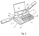
- Fig. 2 die Aufbewahrungsbox nach Fig. 1 beim Herausnehmen und Einstecken des Kupplungsschaftes und
- Fig. 3 die geschlossene Aufbewahrungsbox nach Fig. 1 mit an einer Schmalseite eingestecktem Kupplungsschaft.
- 1 is a perspective view of the storage box with the lid open and the screwdriver bits partially removed,
- Fig. 2 shows the storage box of FIG. 1 when removing and inserting the coupling shaft and
- Fig. 3 shows the closed storage box of FIG. 1 with a coupling shaft inserted on a narrow side.
In den Figuren ist in unterschiedlichen Handhabungsstellungen eine Aufbewahrungsbox 1 veranschaulicht, die dazu dient, mehrere, im gezeigten Beispiel sechs Schraubendreherklingen oder Schraubendrehereinsätzen 2, beispielsweise nach DIN 2126 aufzuheben. Diese Schraubendrehereinsätze werden auch als Bits bezeichnet. Ferner läßt sich in der Aufbewahrungsbox 1 auch ein zugehöriger entsprechender Kupplungsschaft oder Magnethalter 3 unterbringen. Die Aufbewahrungsbox 1 hat etwa quaderförmige Gestalt mit zwei parallel und im Abstand zueinander verlaufenden Flachseiten 4 und 5, zwei parallel und im Abstand zueinander verlaufenden kurzen Schmalseiten 6 und 7 sowie zwei ebenfalls parallel und im Abstand zueinander verlaufenden langen Schmalseiten 8 und 9. Die langen Schmalseiten 8 und 9 sind, wie aus den Figuren ersichtlich, teilzylindrisch abgerundet, während die anderen beiden Schmalseiten 6 und 7, abgesehen von einer kleinen Fase, im wesentlichen flach sind. Im Bereich der langen Schmalseite 9 ist die Aufbewahrungsbox 1 aus den weiter unten erläuterten Gründen unter Ausbildung einer zylindrischen Aufwölbung an der Oberseite verdickt.In the figures, a
Die Aufbewahrungsbox 1 besteht aus einem etwa schalenförmigen Unterteil 11, an dem ein Deckel 12 mittels eines Filmscharniers 13 einstückig angeformt ist. Sie ist ein einziges Kunststofformteil. Der Deckel 12 bildet zusammen mit einer Grifffläche 14 die Oberseite 4 sowie jeweils einen Teil der beiden langen Schmalseiten 8 und 9. Im geschlossenen Zustand ist der Deckel 12 bündig mit der Grifffläche 14 und der Deckel 12 setzt sich auch glatt und bündig in die Kontur der beiden Schmalseiten 8 und 9 fort.The
Das Filmscharnier 13 befindet sich etwa auf halber Höhe der langen Schmalseite 9 und erstreckt sich zu dieser parallel, so daß ein Teil der Schmalseite 9 Bestandteil des Unterteiles 11 und der andere Teil, bezogen auf die Dickenerstreckung, Bestandteil des Deckels 12 ist.The
An der von dem Filmscharnier 13 abliegenden Seite ist der Deckel 12 mit einem der Kontur der Aufbewahrungsbox 1 folgenden Fortsatz 15 versehen. Dieser Fortsatz 15 bildet einen Teil der Schmalseite 8. Der andere Teil der Schmalseite 8 ist ein ein Stück von unten her aufragender Rand 16 des Unterteils, der an einer geraden Kante 17 endet. Zwischen dem Rand 17 und dem Fortsatz 15 des Deckels ist ein gerader in Längsrichtung der Schmalseite 8 sich erstreckender Schlitz 18 begrenzt, in den zum Öffnen des Deckels 12 die Fingerkuppe leicht eindringen soll. Der Schlitz 18 verläuft etwa längs der Mitte der Schmalseite 8 zwischen der Grifffläche 14 und der Schmalseite 7.On the side remote from the
Die Grifffläche 14 ist die Ober- bzw. die Unterseite eines neben dem Deckel 12 liegenden Griffstückes 19, in dem das Unterteil 11 massiv ausgeführt ist. Im Bereich dieses massiven Stückes 19 ist die obere Flachseite 4 bzw. die untere Flachseite 5 mit einer Struktur, beispielsweise in Gestalt kleiner Noppen 21, versehen, damit die Grifffläche 14 weitgehend rutschfest wird.The
Der Deckel 12 sowie das Unterteil 11 begrenzen zusammen eine Kammer 22, die sich innerhalb des Unterteils 11 zwischen den Innenseiten der beiden Schmalseiten 8 und 9 sowie den Innenseiten der Schmalseite 7 und einer entsprechenden Wand 23 des Griffstückes 19 erstreckt. Die Kammer 23 enthält mehrere, im gezeigten Ausführungsbeispiel insgesamt sechse parallel zu den Schmalseiten 6 und 7 ausgerichtete Fächer 24 für die Schraubendrehereinsätze 2. Jedes der Fächer 24 ist ein sacklochartiges Gebilde, dessen Boden 25 in Richtung auf das Filmscharnier 13 und dessen Entnahmeöffnung 26 in Richtung auf die Schmalseite 8 orientiert ist. Die Fächer 24 sind untereinander durch Mittelstege 27 voneinander getrennt, die einstückig mit der Innenfläche der Unterseite 5 verbunden sind. Jedes Fach 24 enthält an seiner dem Deckel 12 zugekehrten Seite einen Schlitz 28, der vom Boden 25 bis hin zu der Entnahmeöffnung 26 reicht und an dieser Stelle ebenfalls offen ist. Die Breite des Schlitzes 28 ist so bemessen, daß einerseits die Schraubendrehereinsätze 2 nicht durch den Schlitz 28 hindurchtreten können, andererseits aber wenigstens so weit, daß sie ein Stück weit mit ihrem Einspannschaft 29 über eine Begrenzungsfläche 31 überstehen können, in der sich die Schlitze 28 befinden. Da die Einspannschäfte 29 sechskantig sind, ist die Weite des Schlitzes 28 etwas größer als die Breitenerstreckung jeder der Sechskantflächen.The
Die Begrenzungsfläche 31 verläuft parallel zu der Flachseite 4, und zwar mit einem Abstand von dieser, der der Dicke des Deckels 12 etwa entspricht.The
Um die Schraubendrehereinsätze 2 reibschlüssig in jedem Fach 24 zu halten, und die entsprechende Seite durch den Schlitz 28 ein Stück weit nach außen drücken zu können, befindet sich in jedem Fach 24 eine Blattfeder 32, die sich, ausgehend von der Innenfläche der dem Deckel 12 gegenüberliegenden unteren Flachseite 5 in das Innere des entsprechenden Faches 24 erhebt, und zwar ausgehend von der Entnahmeöffnung 26 in Richtung auf den Boden 25. Hierdurch entsteht ein etwa trichterförmiges Gebilde, dessen größte Weite in der Nähe der Entnahmeöffnung 26 liegt.In order to hold the
Die Blattfedern 32 sind mit dem Unterteil 11 einstückig, und zwar sind sie zum Zweck der Vereinfachung des Spritzwerkzeuges nach Art einer Ausklinkung ausgebildet, d.h. die untere Flachseite 5 enthält dort, wo sich die Blattfeder 32 befindet, eine gleichgeformte Öffnung. Beim Einschieben eines Schraubendrehereinsatzes 2 in das entsprechende Fach 24 wird die Blattfeder 32 in diese Öffnung weitgehend zurückgedrückt. Die untere Flachseite 5 ist dann bei gefüllten Fächern 24 im wesentlichen glatt. Das Entstehen einer Öffnung durch die nach innen geschwenkte Blattfeder 32 signalisiert ohne Öffnen der Aufbewahrungsbox 1,daß in dem entsprechenden Fach 24 ein Schraubendrehereinsatz 2 fehlt.The leaf springs 32 are in one piece with the
Die Querschnittsgestalt der Fächer 24 ist aus Gründen der Materialersparnis quadratisch. Die Tiefe der Fächer 24, gemessen als Abstand zwischen der Entnahmeöffnung 26, also der der Schmalseite 8 benachbarten Kante der Fläche 31 zu dem Boden 25 entspricht der Länge des Einspannschaftes 29 der Schraubendrehereinsätze 2.The cross-sectional shape of the
Zwischen den Böden 25 der Fächer 24 und der Schmalseite 9, die das Filmscharnier 13 enthält, befindet sich ein weiteres Fach 33, das in seiner Gestalt an den Kupplungsschaft 3 angepaßt ist. Dementsprechend ist der in dem Unterteil 11 befindliche Teil des Faches 33 teilzylindrisch und, da der Durchmesser des Kupplungsschaftes 3 wesentlich größer ist als der Durchmesser der Einspannschäfte 29, ist der Deckel 12 im Bereich des Faches 33 unter Ausbildung eines länglichen teilzylindrischen Wulstes 34 nach außen zu konvex.Between the
An der einen Stirnseite des Faches 33 ist die dort befindliche kurze Schmalseite 7 geteilt, und zwar in einen mit dem Unterteil 11 verbundenen Abschnitt 35 sowie einen an der entsprechenden Stelle an dem Deckel 12 angeformten Abschnitt 36. Die beiden Abschnitte 35 und 36 gehen bei geschlossenem Deckel 12 bündig ineinander über.On one end of the
In Verlängerung des Faches 33 ist auch das Griffstück 19 verdickt ausgeführt, und zwar der Kontur des Deckels 12 folgend, wie dies Fig. 3 erkennen läßt. In diesem verdickten Abschnitt 37 befindet sich eine Durchgangsöffnung 38, deren Achse mit der Längsachse des zylindrischen Faches 33 fluchtet. Der Querschnitt der Durchgangsöffnung 38 ist an einen Einspannschaft 39 der Kupplung 3 im Querschnitt angepaßt und nimmt den Einspannschaft 39 auf, wenn der Kupplungsschaft 3 in das Fach 33 eingelegt ist.In extension of the
Weil die Öffnung 38 als Durchgangsöffnung ausgebildet ist, kann der Kupplungsschaft 3 auch bei geschlossener Aufbewahrungsbox 1, wie dies Fig. 3 zeigt, von außen her eingesteckt werden, um die Aufbewahrungsbox 1 als Behelfshandgriff eines Schraubendrehers zu verwenden. Gleichzeitig sichert die Durchgangsöffnung 38 den Kupplungsschaft 3 gegen versehentliches Herausfallen aus dem Fach 33, wenn der Schaft 39 mit strammem Sitz in die Durchgangsöffnung 38 paßt.Because the
Die Handhabung der Aufbewahrungsbox 1 geschieht folgendermaßen: Zum Entnehmen eines Schraubendrehereinsatzes 2 und des Kupplungsschaftes 3 wird mit einer Hand das Griffstück 19 an den beiden Griffflächen 14 und mit der anderen Hand der Deckel 12 im Bereich des Längsschlitzes 18 angefaßt. Der Deckel 12 kann dann um das Filmscharnier 13 geschwenkt und geöffnet werden, wobei gleichzeitig sämtliche Fächer 24 und das Fach 33 freigegeben werden, da der Abschnitt 36 ebenfalls von der entsprechenden Stirnseite des Faches 33, die der Durchgangsöffnung 38 gegenüberliegt, weggeschwenkt wird. Es läßt sich nun in Längsrichtung des Faches 33 der Kupplungsschaft 3 aus dem Fach 33 herausziehen, wobei der Einspannschaft 39 aus der Durchgangsöffnung 38 herausgezogen wird. Infolge des federnden Anpressens der Schraubendrehereinsätze 2 an die Ränder der Schlitze 28 werden die Schraubendrehereinsätze 2 reibschlüssig festgehalten und können nicht herausfallen, selbst wenn die Aufbewahrungsbox 1 bei geöffnetem Deckel 15 mit den Entnahmeöffnungen 26 nach unten gehalten wird.The handling of the
Das Entnehmen eines Schraubendrehereinsatzes 2 geschieht, indem mit einem Finger der über die Fläche 31 durch den Schlitz 28 hindurch überstehende Sechskantfläche des entsprechenden Schraubendrehereinsatzes 2 erfaßt wird und der Schraubendrehereinsatz 2 durch die Entnahmeöffnung 26 in Richtung auf die Schmalseiten 8 zu vorgeschoben wird. Die Entnahmeöffnung 26 liegt gegenüber der Kante 17 etwas zurückversetzt.A
Da der Rand 16 ein Stück weit über die Innenfläche der unteren Flachseite 5 übersteht, kann auch bei schräg gehaltener Aufbewahrungsbox 1 der Schraubendrehereinsatz 2 nicht herausfallen, wenn er von der Blattfeder 32 freigekommen ist. Er verhakt sich vielmehr mit seinder Schulter an der Kante 17 und muß durch Anfassen an der eigentlichen Klinge herausgenommen werden.Since the
Das Einsetzen geschieht in umgekehrter Reihenfolge, wobei beim Einstecken des Schraubendrehereinsatzes 2 mit seinem Einspannschaft 29 voraus die Blattfeder 32 des entsprechenden Faches in die zugehörige Öffnung der unteren Flachseite 5 zurückgedrückt wird.The insertion takes place in reverse order, whereby when the
Um den Deckel 12 in der geschlossenen Stellung zu halten, in der die Kammer 22 verschlossen ist, sind randseitig an dem Deckel 12 bzw. der Innenseite der Schmalseite 7 sowie der Seitenfläche 23 Vorsprünge und Ausnehmungen vorgesehen, die bei geschlossenem Deckel 12 ineinander verrasten und den Deckel festhalten. Diese Verrastungen sind der Übersichtlichkeit halber nicht dargestellt.In order to keep the
Claims (26)
Priority Applications (1)
| Application Number | Priority Date | Filing Date | Title |
|---|---|---|---|
| AT90100057T ATE81048T1 (en) | 1989-03-03 | 1990-01-03 | STORAGE BOX FOR SCREWDRIVER SOCKETS. |
Applications Claiming Priority (2)
| Application Number | Priority Date | Filing Date | Title |
|---|---|---|---|
| DE3906716A DE3906716A1 (en) | 1989-03-03 | 1989-03-03 | STORAGE BOX FOR SCREWDRIVER INSERTS |
| DE3906716 | 1989-03-03 |
Publications (2)
| Publication Number | Publication Date |
|---|---|
| EP0385055A1 true EP0385055A1 (en) | 1990-09-05 |
| EP0385055B1 EP0385055B1 (en) | 1992-09-30 |
Family
ID=6375383
Family Applications (1)
| Application Number | Title | Priority Date | Filing Date |
|---|---|---|---|
| EP90100057A Expired - Lifetime EP0385055B1 (en) | 1989-03-03 | 1990-01-03 | Storage box for screw driver bits |
Country Status (4)
| Country | Link |
|---|---|
| EP (1) | EP0385055B1 (en) |
| AT (1) | ATE81048T1 (en) |
| DE (2) | DE3906716A1 (en) |
| ES (1) | ES2036058T3 (en) |
Cited By (4)
| Publication number | Priority date | Publication date | Assignee | Title |
|---|---|---|---|---|
| DE29705732U1 (en) * | 1997-04-01 | 1997-08-28 | Mursch Michael Dipl Ing | Containers for the storage and selective dispensing of objects |
| WO1997044163A1 (en) * | 1996-05-22 | 1997-11-27 | Wera Werk Hermann Werner Gmbh & Co. | Storage device for screwdriver bits or the like and chuck therefor |
| DE202014100306U1 (en) | 2014-01-24 | 2014-02-18 | Hazet-Werk Hermann Zerver Gmbh & Co. Kg | Bitbox with optimized storage space utilization |
| CN107199543A (en) * | 2017-07-12 | 2017-09-26 | 昆山义成工具有限公司 | Portable screwdriver head covers box with magnetic extension bar group |
Families Citing this family (8)
| Publication number | Priority date | Publication date | Assignee | Title |
|---|---|---|---|---|
| DE9202838U1 (en) * | 1992-03-04 | 1992-05-27 | Fa. Robert Schroeder, 5600 Wuppertal, De | |
| DE9205913U1 (en) * | 1992-05-01 | 1993-08-26 | Lux Gmbh & Co Kg Emil | Storage box |
| DE9205914U1 (en) * | 1992-05-01 | 1993-08-26 | Lux Gmbh & Co Kg Emil | suitcase |
| DE4300396C2 (en) * | 1993-01-09 | 1997-01-09 | Schuenke & Bockmuehl Gmbh | Tool or wrench set arranged in a housing |
| DE19724974A1 (en) * | 1997-06-13 | 1998-12-17 | Eckhardt Abform Und Giestechni | Box to hold number of screwdriver bits |
| DE10156459A1 (en) | 2001-01-19 | 2002-07-25 | Werner Hermann Wera Werke | Storage device for one or more tools |
| CA2783455A1 (en) | 2011-07-20 | 2013-01-20 | Milwaukee Electric Tool Corporation | Hand tool |
| US8464869B2 (en) | 2011-11-14 | 2013-06-18 | Milwaukee Electric Tool Corporation | Tool case |
Citations (7)
| Publication number | Priority date | Publication date | Assignee | Title |
|---|---|---|---|---|
| BE648191A (en) * | 1963-09-25 | 1964-09-16 | ||
| US4032008A (en) * | 1976-06-07 | 1977-06-28 | Vecchiarelli Richard N | Tool holder guide indicia for tap and drill sets |
| FR2557489A1 (en) * | 1984-01-03 | 1985-07-05 | Holland Letz Felo Werkzeug | Screwdriver bit storing operating handle |
| US4598822A (en) * | 1985-02-19 | 1986-07-08 | Megatool Inc. | Drill bit carrying case |
| DE8801947U1 (en) * | 1988-02-16 | 1988-03-24 | Baum, Peter, 5912 Hilchenbach, De | |
| DE8802681U1 (en) * | 1988-03-01 | 1988-05-11 | Ush Schraubwerkzeugfabrik Ulrich Schmidt, 5912 Hilchenbach, De | |
| EP0270845A2 (en) * | 1986-12-09 | 1988-06-15 | Hans Mesenhöller | Shop-storage means for tools with a clamping shaft, in particular screw-driver bits |
Family Cites Families (7)
| Publication number | Priority date | Publication date | Assignee | Title |
|---|---|---|---|---|
| DE7230306U (en) * | 1973-04-05 | Dreusicke W & Co Kg | Tool case with adjustable tool mounting plates | |
| DE6909398U (en) * | 1969-05-30 | 1969-08-21 | Oswald Burkschat | SCREW HOLDING CLIP FOR SCREWDRIVER |
| DE2906098A1 (en) * | 1979-02-17 | 1980-09-04 | Henckels Zwillingswerk Ag | Manicure case with intermediate tiers - has friction coupling allowing lid to move independently of tier when required |
| DE7918274U1 (en) * | 1979-06-26 | 1979-11-29 | Fa. Haso Philipp Happ, 5207 Ruppichteroth | TOOL BOX, IN PARTICULAR FOR TWIST DRILLS |
| US4644831A (en) * | 1985-07-05 | 1987-02-24 | Miriam Yang | Adaptor sleeve |
| DE8531422U1 (en) * | 1985-11-07 | 1986-01-02 | Fa. Georg Knoblauch, 7928 Giengen | Cassette for storing elongated objects, in particular tools |
| DE8716023U1 (en) * | 1987-12-04 | 1988-01-21 | Wupperfeld, Norbert, 5600 Wuppertal, De |
-
1989
- 1989-03-03 DE DE3906716A patent/DE3906716A1/en active Granted
-
1990
- 1990-01-03 DE DE9090100057T patent/DE59000324D1/en not_active Expired - Lifetime
- 1990-01-03 AT AT90100057T patent/ATE81048T1/en not_active IP Right Cessation
- 1990-01-03 EP EP90100057A patent/EP0385055B1/en not_active Expired - Lifetime
- 1990-01-03 ES ES199090100057T patent/ES2036058T3/en not_active Expired - Lifetime
Patent Citations (7)
| Publication number | Priority date | Publication date | Assignee | Title |
|---|---|---|---|---|
| BE648191A (en) * | 1963-09-25 | 1964-09-16 | ||
| US4032008A (en) * | 1976-06-07 | 1977-06-28 | Vecchiarelli Richard N | Tool holder guide indicia for tap and drill sets |
| FR2557489A1 (en) * | 1984-01-03 | 1985-07-05 | Holland Letz Felo Werkzeug | Screwdriver bit storing operating handle |
| US4598822A (en) * | 1985-02-19 | 1986-07-08 | Megatool Inc. | Drill bit carrying case |
| EP0270845A2 (en) * | 1986-12-09 | 1988-06-15 | Hans Mesenhöller | Shop-storage means for tools with a clamping shaft, in particular screw-driver bits |
| DE8801947U1 (en) * | 1988-02-16 | 1988-03-24 | Baum, Peter, 5912 Hilchenbach, De | |
| DE8802681U1 (en) * | 1988-03-01 | 1988-05-11 | Ush Schraubwerkzeugfabrik Ulrich Schmidt, 5912 Hilchenbach, De |
Cited By (4)
| Publication number | Priority date | Publication date | Assignee | Title |
|---|---|---|---|---|
| WO1997044163A1 (en) * | 1996-05-22 | 1997-11-27 | Wera Werk Hermann Werner Gmbh & Co. | Storage device for screwdriver bits or the like and chuck therefor |
| DE29705732U1 (en) * | 1997-04-01 | 1997-08-28 | Mursch Michael Dipl Ing | Containers for the storage and selective dispensing of objects |
| DE202014100306U1 (en) | 2014-01-24 | 2014-02-18 | Hazet-Werk Hermann Zerver Gmbh & Co. Kg | Bitbox with optimized storage space utilization |
| CN107199543A (en) * | 2017-07-12 | 2017-09-26 | 昆山义成工具有限公司 | Portable screwdriver head covers box with magnetic extension bar group |
Also Published As
| Publication number | Publication date |
|---|---|
| DE3906716A1 (en) | 1990-09-13 |
| DE3906716C2 (en) | 1991-05-08 |
| EP0385055B1 (en) | 1992-09-30 |
| ES2036058T3 (en) | 1993-05-01 |
| ATE81048T1 (en) | 1992-10-15 |
| DE59000324D1 (en) | 1992-11-05 |
Similar Documents
| Publication | Publication Date | Title |
|---|---|---|
| DE3734937C2 (en) | ||
| EP1777042B1 (en) | Device for receiving bits | |
| DE2545049C3 (en) | Container for holding several miniature button cell batteries | |
| EP0385055B1 (en) | Storage box for screw driver bits | |
| AT513898B1 (en) | Device for guiding a ink pad container and self-inking stamp | |
| DE2802460A1 (en) | STACKING DEVICE | |
| DE2113434C3 (en) | Container for holding and individual dispensing of pencil leads | |
| DE3716710A1 (en) | DISPENSER FOR LIGHT-CURING SUBSTANCES | |
| DE2840709A1 (en) | LOCKING UNIT FOR A CONTAINER | |
| DE602004013083T2 (en) | Container that forms a stand in the open position | |
| DE60018914T2 (en) | MULTIPURPOSE PERSONAL HYGIENE DEVICE | |
| DE3638696A1 (en) | Disposable tooth brush | |
| EP0312775A1 (en) | Tool arranged with a blade and a handle | |
| DE102007035475A1 (en) | Compact cosmetics box | |
| EP0270845B1 (en) | Shop-storage means for tools with a clamping shaft, in particular screw-driver bits | |
| EP0818296B1 (en) | Injection moulded object and apparatus for manufacturing the same | |
| DE8521739U1 (en) | Container with a cap that can be opened or closed | |
| DE3127306C2 (en) | ||
| DE19706413A1 (en) | Carrier for single- and stacked-cases | |
| DE1486274A1 (en) | Distribution box for tablets and similar products | |
| DE102018203457B4 (en) | Paint tray, cradle and paint box for paint trays | |
| DE102023204395A1 (en) | CONTAINER FOR FREE-FLOWING POWDER | |
| DE4316941C2 (en) | Device for handling or transferring pipette tips | |
| DE202007016664U1 (en) | Bitbox | |
| DE202008010182U1 (en) | bottles Safe |
Legal Events
| Date | Code | Title | Description |
|---|---|---|---|
| PUAI | Public reference made under article 153(3) epc to a published international application that has entered the european phase |
Free format text: ORIGINAL CODE: 0009012 |
|
| AK | Designated contracting states |
Kind code of ref document: A1 Designated state(s): AT BE CH DE DK ES FR GB GR IT LI LU NL SE |
|
| 17P | Request for examination filed |
Effective date: 19900817 |
|
| GBC | Gb: translation of claims filed (gb section 78(7)/1977) | ||
| 17Q | First examination report despatched |
Effective date: 19920302 |
|
| GRAA | (expected) grant |
Free format text: ORIGINAL CODE: 0009210 |
|
| AK | Designated contracting states |
Kind code of ref document: B1 Designated state(s): AT BE CH DE DK ES FR GB GR IT LI LU NL SE |
|
| PG25 | Lapsed in a contracting state [announced via postgrant information from national office to epo] |
Ref country code: IT Free format text: LAPSE BECAUSE OF FAILURE TO SUBMIT A TRANSLATION OF THE DESCRIPTION OR TO PAY THE FEE WITHIN THE PRE;WARNING: LAPSES OF ITALIAN PATENTS WITH EFFECTIVE DATE BEFORE 2007 MAY HAVE OCCURRED AT ANY TIME BEFORE 2007. THE CORRECT EFFECTIVE DATE MAY BE DIFFERENT FROM THE ONE RECORDED.SCRIBED TIME-LIMIT Effective date: 19920930 Ref country code: GR Free format text: LAPSE BECAUSE OF FAILURE TO SUBMIT A TRANSLATION OF THE DESCRIPTION OR TO PAY THE FEE WITHIN THE PRESCRIBED TIME-LIMIT Effective date: 19920930 Ref country code: DK Effective date: 19920930 Ref country code: SE Effective date: 19920930 |
|
| REF | Corresponds to: |
Ref document number: 81048 Country of ref document: AT Date of ref document: 19921015 Kind code of ref document: T |
|
| REF | Corresponds to: |
Ref document number: 59000324 Country of ref document: DE Date of ref document: 19921105 |
|
| PGFP | Annual fee paid to national office [announced via postgrant information from national office to epo] |
Ref country code: LU Payment date: 19921217 Year of fee payment: 4 |
|
| ET | Fr: translation filed | ||
| GBT | Gb: translation of ep patent filed (gb section 77(6)(a)/1977) |
Effective date: 19930106 |
|
| EPTA | Lu: last paid annual fee | ||
| REG | Reference to a national code |
Ref country code: ES Ref legal event code: FG2A Ref document number: 2036058 Country of ref document: ES Kind code of ref document: T3 |
|
| PLBE | No opposition filed within time limit |
Free format text: ORIGINAL CODE: 0009261 |
|
| STAA | Information on the status of an ep patent application or granted ep patent |
Free format text: STATUS: NO OPPOSITION FILED WITHIN TIME LIMIT |
|
| 26N | No opposition filed | ||
| PG25 | Lapsed in a contracting state [announced via postgrant information from national office to epo] |
Ref country code: LU Free format text: LAPSE BECAUSE OF NON-PAYMENT OF DUE FEES Effective date: 19940103 |
|
| PGFP | Annual fee paid to national office [announced via postgrant information from national office to epo] |
Ref country code: GB Payment date: 20001120 Year of fee payment: 12 |
|
| REG | Reference to a national code |
Ref country code: GB Ref legal event code: IF02 |
|
| PG25 | Lapsed in a contracting state [announced via postgrant information from national office to epo] |
Ref country code: GB Free format text: LAPSE BECAUSE OF NON-PAYMENT OF DUE FEES Effective date: 20020103 |
|
| GBPC | Gb: european patent ceased through non-payment of renewal fee |
Effective date: 20020103 |
|
| PGFP | Annual fee paid to national office [announced via postgrant information from national office to epo] |
Ref country code: AT Payment date: 20061116 Year of fee payment: 18 |
|
| PGFP | Annual fee paid to national office [announced via postgrant information from national office to epo] |
Ref country code: BE Payment date: 20061120 Year of fee payment: 18 |
|
| PGFP | Annual fee paid to national office [announced via postgrant information from national office to epo] |
Ref country code: ES Payment date: 20061211 Year of fee payment: 18 |
|
| PGFP | Annual fee paid to national office [announced via postgrant information from national office to epo] |
Ref country code: NL Payment date: 20070115 Year of fee payment: 18 |
|
| PGFP | Annual fee paid to national office [announced via postgrant information from national office to epo] |
Ref country code: CH Payment date: 20070410 Year of fee payment: 18 |
|
| PGFP | Annual fee paid to national office [announced via postgrant information from national office to epo] |
Ref country code: DE Payment date: 20080130 Year of fee payment: 19 |
|
| BERE | Be: lapsed |
Owner name: STEPHAN *WITTE G.M.B.H. & CO. K.G. Effective date: 20080131 |
|
| REG | Reference to a national code |
Ref country code: CH Ref legal event code: PL |
|
| NLV4 | Nl: lapsed or anulled due to non-payment of the annual fee |
Effective date: 20080801 |
|
| PG25 | Lapsed in a contracting state [announced via postgrant information from national office to epo] |
Ref country code: NL Free format text: LAPSE BECAUSE OF NON-PAYMENT OF DUE FEES Effective date: 20080801 Ref country code: LI Free format text: LAPSE BECAUSE OF NON-PAYMENT OF DUE FEES Effective date: 20080131 Ref country code: CH Free format text: LAPSE BECAUSE OF NON-PAYMENT OF DUE FEES Effective date: 20080131 |
|
| PGFP | Annual fee paid to national office [announced via postgrant information from national office to epo] |
Ref country code: FR Payment date: 20061025 Year of fee payment: 18 |
|
| PG25 | Lapsed in a contracting state [announced via postgrant information from national office to epo] |
Ref country code: AT Free format text: LAPSE BECAUSE OF NON-PAYMENT OF DUE FEES Effective date: 20080103 |
|
| REG | Reference to a national code |
Ref country code: FR Ref legal event code: ST Effective date: 20081029 |
|
| PG25 | Lapsed in a contracting state [announced via postgrant information from national office to epo] |
Ref country code: BE Free format text: LAPSE BECAUSE OF NON-PAYMENT OF DUE FEES Effective date: 20080131 |
|
| REG | Reference to a national code |
Ref country code: ES Ref legal event code: FD2A Effective date: 20080104 |
|
| PG25 | Lapsed in a contracting state [announced via postgrant information from national office to epo] |
Ref country code: FR Free format text: LAPSE BECAUSE OF NON-PAYMENT OF DUE FEES Effective date: 20080131 |
|
| PG25 | Lapsed in a contracting state [announced via postgrant information from national office to epo] |
Ref country code: ES Free format text: LAPSE BECAUSE OF NON-PAYMENT OF DUE FEES Effective date: 20080104 |
|
| PG25 | Lapsed in a contracting state [announced via postgrant information from national office to epo] |
Ref country code: DE Free format text: LAPSE BECAUSE OF NON-PAYMENT OF DUE FEES Effective date: 20090801 |