EP0385035B1 - High-pressure crystallographic observation apparatus - Google Patents
High-pressure crystallographic observation apparatus Download PDFInfo
- Publication number
- EP0385035B1 EP0385035B1 EP89312958A EP89312958A EP0385035B1 EP 0385035 B1 EP0385035 B1 EP 0385035B1 EP 89312958 A EP89312958 A EP 89312958A EP 89312958 A EP89312958 A EP 89312958A EP 0385035 B1 EP0385035 B1 EP 0385035B1
- Authority
- EP
- European Patent Office
- Prior art keywords
- pressure
- sample
- crystallographic
- observation apparatus
- transparent
- Prior art date
- Legal status (The legal status is an assumption and is not a legal conclusion. Google has not performed a legal analysis and makes no representation as to the accuracy of the status listed.)
- Expired - Lifetime
Links
- 239000002775 capsule Substances 0.000 claims description 23
- 230000004927 fusion Effects 0.000 description 24
- 239000013078 crystal Substances 0.000 description 16
- 238000002425 crystallisation Methods 0.000 description 13
- 230000008025 crystallization Effects 0.000 description 13
- 230000001965 increasing effect Effects 0.000 description 13
- 239000007788 liquid Substances 0.000 description 13
- 239000000126 substance Substances 0.000 description 13
- 238000000034 method Methods 0.000 description 10
- 230000008569 process Effects 0.000 description 9
- 230000003247 decreasing effect Effects 0.000 description 7
- 230000003287 optical effect Effects 0.000 description 7
- 239000012780 transparent material Substances 0.000 description 7
- 238000005259 measurement Methods 0.000 description 6
- 230000007246 mechanism Effects 0.000 description 6
- 238000010438 heat treatment Methods 0.000 description 5
- 239000007787 solid Substances 0.000 description 5
- 238000010276 construction Methods 0.000 description 4
- 238000003825 pressing Methods 0.000 description 4
- 230000009467 reduction Effects 0.000 description 4
- 239000002002 slurry Substances 0.000 description 4
- 230000008033 biological extinction Effects 0.000 description 3
- 239000000463 material Substances 0.000 description 3
- 229920002379 silicone rubber Polymers 0.000 description 3
- 238000005406 washing Methods 0.000 description 3
- 230000008901 benefit Effects 0.000 description 2
- 230000005540 biological transmission Effects 0.000 description 2
- 239000013013 elastic material Substances 0.000 description 2
- 230000002708 enhancing effect Effects 0.000 description 2
- 238000004519 manufacturing process Methods 0.000 description 2
- 238000002844 melting Methods 0.000 description 2
- 230000008018 melting Effects 0.000 description 2
- 239000000203 mixture Substances 0.000 description 2
- 230000001105 regulatory effect Effects 0.000 description 2
- 229910052594 sapphire Inorganic materials 0.000 description 2
- 239000010980 sapphire Substances 0.000 description 2
- 238000007711 solidification Methods 0.000 description 2
- 230000008023 solidification Effects 0.000 description 2
- 230000033228 biological regulation Effects 0.000 description 1
- 238000009530 blood pressure measurement Methods 0.000 description 1
- 230000008859 change Effects 0.000 description 1
- 230000006866 deterioration Effects 0.000 description 1
- 238000005286 illumination Methods 0.000 description 1
- 239000007791 liquid phase Substances 0.000 description 1
- 239000005304 optical glass Substances 0.000 description 1
- 239000002245 particle Substances 0.000 description 1
- 230000000704 physical effect Effects 0.000 description 1
- 239000004033 plastic Substances 0.000 description 1
- 229920003023 plastic Polymers 0.000 description 1
- 229920013716 polyethylene resin Polymers 0.000 description 1
- 238000007789 sealing Methods 0.000 description 1
- 238000000926 separation method Methods 0.000 description 1
- 239000007790 solid phase Substances 0.000 description 1
Images

Classifications
-
- G—PHYSICS
- G01—MEASURING; TESTING
- G01N—INVESTIGATING OR ANALYSING MATERIALS BY DETERMINING THEIR CHEMICAL OR PHYSICAL PROPERTIES
- G01N21/00—Investigating or analysing materials by the use of optical means, i.e. using sub-millimetre waves, infrared, visible or ultraviolet light
- G01N21/01—Arrangements or apparatus for facilitating the optical investigation
- G01N21/03—Cuvette constructions
- G01N21/0317—High pressure cuvettes
-
- G—PHYSICS
- G01—MEASURING; TESTING
- G01N—INVESTIGATING OR ANALYSING MATERIALS BY DETERMINING THEIR CHEMICAL OR PHYSICAL PROPERTIES
- G01N25/00—Investigating or analyzing materials by the use of thermal means
- G01N25/14—Investigating or analyzing materials by the use of thermal means by using distillation, extraction, sublimation, condensation, freezing, or crystallisation
- G01N25/147—Investigating or analyzing materials by the use of thermal means by using distillation, extraction, sublimation, condensation, freezing, or crystallisation by cristallisation
-
- G—PHYSICS
- G01—MEASURING; TESTING
- G01N—INVESTIGATING OR ANALYSING MATERIALS BY DETERMINING THEIR CHEMICAL OR PHYSICAL PROPERTIES
- G01N21/00—Investigating or analysing materials by the use of optical means, i.e. using sub-millimetre waves, infrared, visible or ultraviolet light
- G01N21/84—Systems specially adapted for particular applications
- G01N2021/8477—Investigating crystals, e.g. liquid crystals
-
- Y—GENERAL TAGGING OF NEW TECHNOLOGICAL DEVELOPMENTS; GENERAL TAGGING OF CROSS-SECTIONAL TECHNOLOGIES SPANNING OVER SEVERAL SECTIONS OF THE IPC; TECHNICAL SUBJECTS COVERED BY FORMER USPC CROSS-REFERENCE ART COLLECTIONS [XRACs] AND DIGESTS
- Y10—TECHNICAL SUBJECTS COVERED BY FORMER USPC
- Y10T—TECHNICAL SUBJECTS COVERED BY FORMER US CLASSIFICATION
- Y10T117/00—Single-crystal, oriented-crystal, and epitaxy growth processes; non-coating apparatus therefor
- Y10T117/10—Apparatus
- Y10T117/1024—Apparatus for crystallization from liquid or supercritical state
- Y10T117/1096—Apparatus for crystallization from liquid or supercritical state including pressurized crystallization means [e.g., hydrothermal]
Definitions
- the present invention relates to a high-pressure crystallographic observation apparatus for observing the crystals of substances under a high pressure and, more specifically, to a high-pressure crystallographic observation apparatus such as for observing the forms of crystals and physical variations including processes of growth and extinction of crystals and for measuring the pressure of fusion of a solid by varying pressure at a constant temperature.
- Crystals are observed under pressure to obtain data representing the physical variations of the crystals under pressure.
- FIG. 6 Shown in Fig. 6 is a typical, conventional crystallographic observation apparatus for the observation of crystals under pressure.
- This crystallographic observation apparatus comprises a pressure vessel 3 provided with opposite, transparent observation window blocks 1 and 2 formed of a transparent material, and a pressurizing device 4 for enhancing the internal pressure of the pressure vessel 3.
- a pipe 5 is connected to the pressurizing device 4 to inject a sample to be observed into the pressurizing device 4.
- the pressurizing device 4 is connected to the pressure vessel 3 by a pressure pipe 6.
- the internal pressure of the pressure vessel 3 is measured by a pressure gage 19 of an optional type connected to the pressure pipe 6.
- This crystallographic observation apparatus is operated for the observation of crystals in the following manner.
- a sample is injected through the pipe 5 into the pressurizing device 4.
- the pressurizing device 4 supplies the sample through the pressure pipe 6 into the sample chamber 7 of the pressure vessel, and then the sample filled in the sample changer 7 is illuminated through the transparent observation window block 2 by a light source 8 to enable the observation of the sample with a microscope through the transparent observation window block 1.
- the pressurizing device 4 increases the internal pressure of the pressure vessel 3 to pressurize the sample filling the sample chamber 7. Crystallization progresses as the internal pressure is increased. The form of the crystals and the process of growth of the crystals are observed while the internal pressure of the sample chamber 7 is being increased. The process of extinction of the crystals is observed as the internal pressure of the sample chamber is decreased.
- This conventional crystallographic observation apparatus has the following disadvantages.
- a comparatively large amount of sample is necessary to fill up the sample chamber of the pressure vessel by injecting the sample into the pressurizing device and supplying the sample through the pressure pipe to the sample chamber, because the pressurizing device and the pressure pipe must be filled up with the sample as well as the sample chamber.
- the sample for observation is a new substance, and it is difficult to prepare a large amount of such a new substance.
- only a small amount of sample is available even if the sample is not a new substance. Accordingly, requiring a large amount of sample is a significant disadvantage.
- a pipe having a very small inside diameter is used as the pressure pipe particularly when the crystallographic observation apparatus is used for observation under a high pressure. Therefore, a solid sample is unable to be introduced in to the sample chamber. It is particularly difficult to introduce a slurry sample containing nonsoluble solid particles into the sample chamber due to the high viscosity of the slurry sample.
- a liquid sample of a substance having a comparatively high melting point is liable to be caused to solidify within the pressure pipe even by slight decrease in temperature or by increase in pressure while the liquid sample is being injected through the pressure pipe, and often clogs the pressure pipe. Consequently, the pressurizing device is unable to increase the internal pressure of the sample chamber to a predetermined pressure.
- the solidification of the liquid sample may be obviated by heating the pressure pipe, which, however, may possibly entail excessive heating of the liquid sample. Accordingly, the pressure pipe must be heated for such a purpose under strict temperature control, which is very difficult. Heating the pressure pipe also heats the pressure gage to make accurate pressure measurement impossible.
- the interior of the pressurizing device, the pressure vessel and the pressure pipe must be washed perfectly after the completion of observation of a sample prior to the supply of another sample into the sample chamber of the pressure vessel, which requires much time because many parts must be washed. Washing the interior of the pressure pipe, in particular, is very difficult and requires much time because the pressure pipe has a very small inside diameter. Finish washing using the next sample requires an additional amount of sample for washing.
- the transparent observation window blocks of the conventional crystallographic observation apparatus is cylindrical and each transparent observation window block is seated on a flat seat, and hence the thickness of the transparent observation window blocks must be comparatively large to secure a sufficient strength against pressure. Accordingly, the objective lens of the microscope is disposed inevitably at a comparatively long distance from the sample, so that the microscope is unable to be focused at a high magnification and hence the sample cannot sufficiently be magnified for observation.
- the pressure of fusion of crystals is another very important data for the use and manufacture of a solid obtained by crystallization.
- Fig. 7 Shown in Fig. 7 is an essential portion of another conventional crystallographic observation apparatus capable of measuring the pressure of fusion.
- This crystallographic observation apparatus comprises, as principal components, a pressure vessel 17 having a sample chamber 18, a plunger 16 fitting the sample chamber 18, pressure measuring means, not shown, for measuring the internal pressure of the sample chamber 18, and pressing means, not shown, for pressing the plunger 16.
- a liquid sample is poured into the sample chamber 18, the liquid sample is compressed by the plunger 16 for solidification, and then the internal pressure of the sample chamber 18 is reduced and, at the same time, the volume variation ⁇ V of the sample chamber 18 and the internal pressure P of the sample chamber 18 are measured to determine the relation between ⁇ V and P.
- This conventional crystallographic observation apparatus has the following disadvantages.
- the crystallographic observation apparatus Indirectly measuring the pressure of fusion from the ⁇ V-P relation, the crystallographic observation apparatus is unable to determine the pressure of fusion accurately, and hence this crystallographic observation apparatus has a basic problem that the accuracy of measurement is not high enough.
- a discontinuous point appears on the ⁇ V-P curve at the pressure of fusion, however, practically, the gradient of the ⁇ V-P curve in the vicinity of the pressure of fusion changes gradually instead of sharp change and, at the worst, it occurs, with some substances, that the determination of the pressure of fusion is entirely impossible.
- French Patent Specification No 2 566 903 discloses an apparatus for the analysis of samples which are contained in an enclosure.
- the present invention is based on the finding that crystallographic observation can be advantageously carried out under high pressure when the sample is introduced into the pressure vessel in a small elastic container.
- a high-pressure crystallographic observation apparatus comprising: a pressure vessel having a cavity and provided with a transparent observation window block in the vessel wall; and pressurizing means for pressuring the cavity of the pressure vessel; characterised by a feed channel in the vessel wall connecting said pressurizing means to said vessel cavity, and a small elastic sample containing means for containing a sample, sealed within the cavity of the pressure vessel.
- the apparatus of the invention enables a relatively small amount of sample to be required for observation.
- the apparatus is capable of being charged with the sample comparatively easily and in a short time, capable of constantly regulating the pressure of the sample at a set value, eliminating the need of heating of the pressure pipe, capable of keeping the sample at a set temperature, and capable of comparatively easily being washed perfectly.
- a further advantage is that the apparatus is capable of accurately measuring the pressure of fusion of a substance using a comparatively small amount of sample even if the substance does not have a distinct point of discontinuity on the ⁇ V-P curve.
- the pressure increasing means may be arranged to supply a pressure medium through a pressure pipe to the cavity of the pressure vessel and may pressurize the pressure medium to a set pressure to pressurize the small elastic vessel, so that the internal pressure of the sample chamber is increased to apply the set pressure to the sample contained in the sample chamber.
- a set pressure can be applied to the sample by decreasing the internal pressure of the cavity to the set pressure after increasing the internal pressure to a higher set pressure.
- a crystallographic observation apparatus comprises a pressure vessel having a cavity and provided with transparent observation window blocks respectively in opposite walls thereof, a small elastic vessel defining a sample chamber in the cavity together with one of the transparent observation window blocks to seal a sample in a pressure-tight fashion, and pressurizing means for enhancing the internal pressure of the cavity of the pressure vessel.
- the sample may be illuminated from outside the sample chamber through the transparent observation window block defining the sample chamber.
- the elastic vessel is formed of a transparent material or is provided with a transparent window, the sample can be illuminated through one of the transparent observation window blocks and can be observed through the other transparent observation window block.
- the sample Since the sample is sealed in a pressure-tight fashion in the sample chamber, the sample is not contaminated by the pressure medium and the purity of the sample can be kept at the initial purity.
- the crystallographic observation apparatus needs only a very small amount of sample for observation.
- the small elastic vessel containing the sample is placed in the cavity of the pressure vessel in charging the pressure vessel with the sample. Accordingly, even solid samples and slurry samples, which are difficult to put in the sample chamber through the pressure pipe, can readily be placed in the sample chamber in a short time similarly to liquid samples.
- This manner of placing a sample in the sample chamber solves a problem that a sample having a high melting point may solidify in th pressure pipe and clog the pressure pipe to make the application of a test pressure to the sample impossible, because the sample is contained beforehand in the sample chamber and a pressure medium hard to solidify can be used. Accordingly, the pressure pipe need not be heated, there is the least apprehension of the physical properties of the sample being changed by heat and deterioration of the accuracy of the pressure gage by heat, so that the pressure acting on the sample can accurately be measured.
- the sample is sealed in the sample chamber defined by the transparent observation window block and the small elastic vessel, only the transparent observation window block and the small elastic vessel need to be washed, or another small elastic vessel is used and only the transparent observation window block is washed for the observation of another sample.
- a crystallographic observation apparatus comprises a pressure vessel having a cavity and provided with a transparent observation window block in one side wall thereof, a small, sealed elastic capsule for containing a sample, provided with a transparent window at least in its side wall facing the transparent observation window block and to be placed in the cavity of the pressure vessel, and pressurizing means for pressurizing the cavity of the pressure vessel. Accordingly, only the small, sealed elastic capsule must be washed or another small, sealed elastic capsule is used for the observation of another sample.
- the sample is illuminated through the transparent observation window block and the transparent wall of the small, sealed elastic capsule for observation.
- the pressure vessel may be provided with another transparent observation window block in a wall opposite the wall in which the former transparent observation window block is provided.
- the small, sealed elastic capsule is formed of a transparent material or both the side walls respectively facing the transparent observation window blocks are formed of a transparent material.
- Such a small, sealed elastic capsule enables the illumination of the sample through one of the transparent observation window blocks and the observation of the sample through the other transparent observation window block.
- the transparent observation window blocks may be formed of any material in any shape provided that a sufficiently high transmissivity and a sufficient strength are secured.
- the transparent observation window blocks for example, are semispherical or cylindrical blocks of sapphire, a hard optical glass or a hard optical plastic.
- the transparent observation window blocks are semispherical blocks placed in the pressure vessel with their circular flat surfaces on the inner side of the pressure vessel. The thickness of such a semispherical transparent observation window block to ensure the strength of the transparent observation window block to withstand an operating pressure is comparatively small, so that the microscope can be disposed with its objective lens at a comparatively short distance from the sample, and hence the microscope can be focused at a high magnification to observe the sample at a sufficiently high magnification.
- the small elastic capsule need not entirely be formed of an elastic material, but may be such as having an elastic portion which extends or contracts elastically to vary the volume of the small elastic capsule.
- Shown in Fig. 2 is a sample chamber defined by a cylindrical transparent window block 16 and a small, bottomed cylindrical container formed by connecting a transparent bottom member 18 to an elastic cylindrical member 17.
- the elastic cylindrical member 17 expands or contracts according to pressure that acts thereon.
- the bottom member 18 need not necessarily be formed of a transparent material.
- the small elastic capsule must be elastic and transparent. However, the small elastic capsule need not entirely be formed of a transparent material.
- a small capsule as shown in Fig. 4 may be employed. This small capsule comprises a cylindrical elastic member 17, a bottom member 18 joined to the lower end of the cylindrical elastic member 17, and a transparent disk 20 joined to the upper end of the cylindrical elastic member 17.
- the cylindrical elastic member 17 and the bottom member 18 may be either transparent or opaque.
- the elastic portion of the small, elastic capsule may be formed, for example, of silicon rubber or a polyethylene resin. There is no particular restriction on the material of the elastic portion provided that the material is elastic.
- the shape of the elastic vessel may be a flanged rectangular parallelepiped or a flanged semisphere.
- the elastic vessel may be provided partially with a bellows.
- the shape of the elastic capsule may be a rectangular parallelepiped or a sphere. However, there is no particular restriction on the shapes of the elastic vessel and the elastic capsule.
- the internal pressure of the pressure vessel is increased to solidify the sample, and then the sample is observed as the internal pressure of the pressure vessel is decreased gradually.
- a pressure at the completion of fusion of the solidified sample i.e., the pressure of fusion
- the pressure of fusion can surely be measured at a high accuracy even if the ⁇ V-P curve of the sample does not have a sharp point of discontinuity.
- the crystallographic observation apparatus is provided with photographing means, such as a TV camera, and display means, such as a TV monitor, capable of displaying the image of the sample and numerical data indicating the temperature and the pressure within the pressure vessel to facilitate the observation of the sample and to achieve the observation of the sample at a satisfactory accuracy.
- photographing means such as a TV camera
- display means such as a TV monitor
- Such means magnifies the sample and enables the observation in an easy position.
- the crystallographic observation apparatus is provided with recording means, such as a video tape recorder, for recording the image of the sample.
- recording means such as a video tape recorder
- the record enables the review of the results of observation and the automatic measurement of the pressure of fusion.
- the crystallographic observation apparatus may be provided with transmissivity measuring means near one of the transparent observation window blocks.
- a crystallographic observation apparatus comprises a pressure vessel 3 in the form of a block having a cavity 7, a pressurizing device 4 for pressurizing the pressure vessel 3, and a pressure pipe 6 connecting the pressurizing device 4 to the pressure vessel 3.
- a pipe 5 is connected to the pressurizing device 4 to supply a pressure medium 15 to the pressurizing device 4.
- the pressure vessel 3 is provided with a first semispherical observation window block 1 and a second semispherical observation window block 2 respectively in the upper and lower side walls thereof.
- the first and second observation window blocks 1 and 2 are formed of sapphire and are held in place by observation window block holding members 12 with their flat circular surfaces facing the cavity 7 of the pressure vessel 3.
- the observation window block holding members 12 are screwed in the pressure vessel 3.
- O rings 13 are provided to seal the interfaces between the observation window block holding members 12 and the pressure vessel 3.
- the central portions of the spherical surfaces of the first and second observation window blocks 1 and 2 are flattened to enable the exact observation of a sample.
- a small, transparent elastic vessel 10 is formed entirely of silicon rubber.
- the flange of the elastic vessel 10 is pressed firmly against the periphery of the flat circular surface of the first observation window block 1 and the lower end of the observation window block holding member 12 by a fastening ring 11 screwed on the lower portion of the observation window block holding member 12 to form a pressure-tight sample chamber 9 defined by the first observation window block 1 and the elastic vessel 10.
- the sample is sealed in the sample chamber.
- the pressurizing device 4 is connected by a pressure pipe 6 and a channel in the vessel wall to the interior of the pressure vessel 3, and a strain gage pressure sensor 19 is provided on the pressure pipe 6.
- the process of crystallization of a liquid sample was observed by the crystallographic observation apparatus.
- the pressure medium 15 was supplied by the pressurizing device 4 to the pressure vessel 3 to fill up the cavity 7.
- the liquid sample was illuminated through the second observation window block 2 by a light source 8 for observation by an optical microscope, not shown, disposed outside the pressure vessel 3 near the first observation window block 1.
- the cavity 7 was pressurized by increasing the pressure of the pressure medium 15 filled in the cavity 7 by the pressurizing device 4 to apply increasing pressure to the liquid sample.
- the elastic vessel 10 was caused to contract gradually and crystals began to form in the liquid sample when the internal pressure of the cavity 7 reached the crystallization pressure.
- the crystallization pressure measured by the crystallographic observation apparatus was equal to that measured by the conventional crystallographic observation apparatus.
- a sample having a pressure of fusion was subjected to the measurement of the pressure of fusion by the crystallographic observation apparatus.
- the pressure medium 15 was supplied through the pressure pipe 6 to the pressure vessel 3 by the pressurizing device 4 to fill up the cavity 7 of the pressure vessel 3 with the pressure medium 15 and the sample was illuminated through the second observation window block 2 by the light source 8. The condition of the sample was observed through the first observation window block 1.
- the pressure of the pressure medium 15 filled in the cavity 7 was increased gradually by the pressurizing device 4 to apply pressure to the sample.
- the elastic vessel 10 contracted gradually as the pressure of the pressure medium 15 was increased.
- the internal pressure of the sample chamber 9 was measured by the strain gage pressure sensor 19 provided on the pressure pipe 6.
- the internal pressure of the sample chamber 9 was increased to a level where the sample was solidified, and then the internal pressure of the sample chamber 9 was decreased gradually. While the internal pressure of the sample chamber 9 was being decreased, the internal pressure of the sample chamber was measured continuously by the strain gage pressure sensor 19 and the condition of the sample was observed.
- the measured pressure of fusion thus determined was higher than the reference value only by 0.2% of the reference value. This measured pressure of fusion is very accurate as compared with that measured by the conventional crystallographic observation apparatus, which is higher than the reference value by 2.5% of the reference value.
- a crystallographic observation apparatus in a second embodiment according to the present invention is substantially the same in construction and function as the crystallographic observation apparatus in the first embodiment, except that a pressure vessel employed in the second embodiment is provided with only one observation window block 1, and an opaque elastic vessel 10 is employed.
- the crystallographic observation apparatus in the second embodiment employs a reflection optical microscope instead of a transmission optical microscope for the observation of the sample. The performance of this crystallographic observation apparatus was the same as that of the foregoing crystallographic observation apparatus in the first embodiment.
- a crystallographic observation apparatus in a third embodiment according to the present invention is substantially the same in construction and function as the crystallographic observation apparatus in the first embodiment, except that a pressure vessel 3 employed in the third embodiment is provided with only one observation window block 1, and a small, transparent elastic capsule 10 is employed for containing a sample.
- the crystallographic observation apparatus in the third embodiment employs a reflection optical microscope instead of a transmission optical microscope for the observation of the sample.
- the upper wall of the elastic capsule 10 facing the observation window block 1 is formed of a transparent material and the rest of the walls are formed of an opaque elastic material.
- a crystallographic observation apparatus in a fourth embodiment comprises a pressure vessel 3 having a cavity 7, and a pressurizing device 4 directly connected to the pressure vessel 3.
- the pressure vessel 3 is substantially the same in construction and configuration as that of the crystallographic observation apparatus in the third embodiment, and hence the description thereof will be omitted to avoid duplication.
- the pressurizing device 4 comprises a plunger 17 fitted in a through hole 16 formed in one side wall 14 of the pressure vessel 3 so as to communicate with the cavity 7 of the pressure vessel 3, and a driving mechanism 20 for driving the plunger 17.
- Indicated at 24 is a pressure-tight sealing member.
- the driving mechanism 20 comprises an electric motor 23, a worm reduction gear 22 having a worm fixedly mounted on the output shaft of the electric motor 23 and a worm wheel engaging the worm and fixedly mounted on one end of a driving shaft, and a screw-nut pressing mechanism comprising an internally threaded rotary member 21 attached to the other end of the driving shaft, and a screw rod 18 engaging the internal thread 25 of the rotary member 21 and joined to the plunger 17.
- the plunger 17 is driven for movement toward or away from the cavity 7 through the worm reduction gear 22 and the screw-nut pressing mechanism by the electric motor 23 to apply pressure to or to relieve pressure from a pressure medium 15 filling up the cavity 7 and the through hole 16.
- a small, elastic capsule 10 for containing a sample is formed entirely of transparent silicon rubber. A sample is contained in the sample chamber 9 of the elastic capsule 10.
- the sample In observing the condition of the sample contained in the elastic capsule 10 placed in the cavity 7 of the pressure vessel 3, the sample is illuminated through the observation window block 1 by a light source 8, the pressure medium 15 is filled in the cavity 7 and the through hole 16, and then the plunger 17 is advanced by the electric motor 23 to apply pressure to the sample contained in the sample chamber 9 of the elastic capsule 10 by pressurizing the pressure medium 15 filled in the cavity 7 and the through hole 16.
- the condition of the sample under pressure is observed with an optical microscope, not shown, through the observation window block 1.
- a pressure at which crystallization occurs is determined while the pressure in the cavity 4 is increased to a high pressure level where the sample is solidified, and the pressure of fusion is determined while the pressure is decreased gradually from the high pressure level.
- the worm reduction gear 22 may be driven by a manual driving mechanism instead of the electric motor 23.
- the use of the electric motor 23 for driving the worm reduction gear 22 makes possible discretionary pressure control, pressurization at a constant rate and employment of a computer for complicated pressure regulation.
- This crystallographic observation apparatus needs a comparatively small amount of pressure medium necessary for filling up only the cavity 7 and the through hole 16, so that the pressurizing device 4 may be of a comparatively small capacity or the pressure medium can be pressurized or the pressure applied to the pressure medium can be decreased in a comparatively short time.
- the pressurizing device 4 is connected directly to the pressure vessel 3 omitting a pressure pipe and the pressurizing system employing the plunger 17 is inherently resistant to the leakage of the pressure medium, there is the least possibility of the leakage of the pressure medium.
- the pressurizing device 4 is connected directly to the pressure vessel 3 without using any pipe, the plunger 17 is fitted in the through hole 16 formed in the side wall 14 of the pressure vessel 3, and only the driving mechanism is disposed outside the pressure vessel 3, the crystallographic observation apparatus including the pressuring device can be formed in a compact construction.
- the crystallographic observation apparatus in accordance with the present invention requires a comparatively small amount of sample, facilitates the placement of the sample in the cavity of the pressure vessel, enables the placement of the sample in the cavity of the pressure vessel in a comparatively short time, is capable of accurately regulating the pressure applied to the sample, eliminates heating the sample in introducing the sample in the cavity of the pressure vessel, is capable of being washed comparatively easily for the subsequent observation of the next sample, and enables the microscope to be disposed with the objective lens thereof at a comparatively short distance from the sample for the observation of the sample at a high magnification.
Landscapes
- Physics & Mathematics (AREA)
- Health & Medical Sciences (AREA)
- Life Sciences & Earth Sciences (AREA)
- Chemical & Material Sciences (AREA)
- Analytical Chemistry (AREA)
- Biochemistry (AREA)
- General Health & Medical Sciences (AREA)
- General Physics & Mathematics (AREA)
- Immunology (AREA)
- Pathology (AREA)
- Investigating Or Analysing Materials By Optical Means (AREA)
- Sampling And Sample Adjustment (AREA)
Description
- The present invention relates to a high-pressure crystallographic observation apparatus for observing the crystals of substances under a high pressure and, more specifically, to a high-pressure crystallographic observation apparatus such as for observing the forms of crystals and physical variations including processes of growth and extinction of crystals and for measuring the pressure of fusion of a solid by varying pressure at a constant temperature.
- Elucidation of forms of crystals and physical variations including processes of growth and extinction of crystals under pressure is very important for the manufacture or use of chemical substances under pressure.
- For example, knowledge of such physical variations of crystals is an indispensable requirement of the pressure crystallization process, which has been a remarkable technique of separating a specified substance from a mixture and purifying the specified substance, because the pressure crystallization process is a separating and purifying process of producing a specified substance of high purity by separating the specified substance by crystallization from a liquid or slurry mixture by the agency of a high pressure. Accordingly, it is necessary to know previously the pressure necessary for the separation and growth of crystals and a pressure condition for satisfactory crystallization.
- Crystals are observed under pressure to obtain data representing the physical variations of the crystals under pressure.
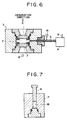
- Shown in Fig. 6 is a typical, conventional crystallographic observation apparatus for the observation of crystals under pressure. This crystallographic observation apparatus comprises a
pressure vessel 3 provided with opposite, transparentobservation window blocks 1 and 2 formed of a transparent material, and a pressurizingdevice 4 for enhancing the internal pressure of thepressure vessel 3. Apipe 5 is connected to the pressurizingdevice 4 to inject a sample to be observed into the pressurizingdevice 4. The pressurizingdevice 4 is connected to thepressure vessel 3 by apressure pipe 6. The internal pressure of thepressure vessel 3 is measured by apressure gage 19 of an optional type connected to thepressure pipe 6. - This crystallographic observation apparatus is operated for the observation of crystals in the following manner. A sample is injected through the
pipe 5 into the pressurizingdevice 4. The pressurizingdevice 4 supplies the sample through thepressure pipe 6 into thesample chamber 7 of the pressure vessel, and then the sample filled in thesample changer 7 is illuminated through the transparentobservation window block 2 by alight source 8 to enable the observation of the sample with a microscope through the transparent observation window block 1. - Then, the pressurizing
device 4 increases the internal pressure of thepressure vessel 3 to pressurize the sample filling thesample chamber 7. Crystallization progresses as the internal pressure is increased. The form of the crystals and the process of growth of the crystals are observed while the internal pressure of thesample chamber 7 is being increased. The process of extinction of the crystals is observed as the internal pressure of the sample chamber is decreased. - This conventional crystallographic observation apparatus, however, has the following disadvantages.
- A comparatively large amount of sample is necessary to fill up the sample chamber of the pressure vessel by injecting the sample into the pressurizing device and supplying the sample through the pressure pipe to the sample chamber, because the pressurizing device and the pressure pipe must be filled up with the sample as well as the sample chamber.
- In most cases, the sample for observation, as a matter of course, is a new substance, and it is difficult to prepare a large amount of such a new substance. In some cases, only a small amount of sample is available even if the sample is not a new substance. Accordingly, requiring a large amount of sample is a significant disadvantage.
- A pipe having a very small inside diameter is used as the pressure pipe particularly when the crystallographic observation apparatus is used for observation under a high pressure. Therefore, a solid sample is unable to be introduced in to the sample chamber. It is particularly difficult to introduce a slurry sample containing nonsoluble solid particles into the sample chamber due to the high viscosity of the slurry sample.
- Particularly, a liquid sample of a substance having a comparatively high melting point is liable to be caused to solidify within the pressure pipe even by slight decrease in temperature or by increase in pressure while the liquid sample is being injected through the pressure pipe, and often clogs the pressure pipe. Consequently, the pressurizing device is unable to increase the internal pressure of the sample chamber to a predetermined pressure. The solidification of the liquid sample may be obviated by heating the pressure pipe, which, however, may possibly entail excessive heating of the liquid sample. Accordingly, the pressure pipe must be heated for such a purpose under strict temperature control, which is very difficult. Heating the pressure pipe also heats the pressure gage to make accurate pressure measurement impossible.
- The interior of the pressurizing device, the pressure vessel and the pressure pipe must be washed perfectly after the completion of observation of a sample prior to the supply of another sample into the sample chamber of the pressure vessel, which requires much time because many parts must be washed. Washing the interior of the pressure pipe, in particular, is very difficult and requires much time because the pressure pipe has a very small inside diameter. Finish washing using the next sample requires an additional amount of sample for washing.
- Furthermore, as shown in Fig. 6, the transparent observation window blocks of the conventional crystallographic observation apparatus is cylindrical and each transparent observation window block is seated on a flat seat, and hence the thickness of the transparent observation window blocks must be comparatively large to secure a sufficient strength against pressure. Accordingly, the objective lens of the microscope is disposed inevitably at a comparatively long distance from the sample, so that the microscope is unable to be focused at a high magnification and hence the sample cannot sufficiently be magnified for observation.
- The pressure of fusion of crystals is another very important data for the use and manufacture of a solid obtained by crystallization.
- Shown in Fig. 7 is an essential portion of another conventional crystallographic observation apparatus capable of measuring the pressure of fusion. This crystallographic observation apparatus comprises, as principal components, a
pressure vessel 17 having asample chamber 18, aplunger 16 fitting thesample chamber 18, pressure measuring means, not shown, for measuring the internal pressure of thesample chamber 18, and pressing means, not shown, for pressing theplunger 16. - In measuring the pressure of fusion by the crystallographic observation apparatus, a liquid sample is poured into the
sample chamber 18, the liquid sample is compressed by theplunger 16 for solidification, and then the internal pressure of thesample chamber 18 is reduced and, at the same time, the volume variation ΔV of thesample chamber 18 and the internal pressure P of thesample chamber 18 are measured to determine the relation between ΔV and P. The value of P corresponding to a point on the ΔV-P curve where the volume of the sample chamber varies sharply with respect to the variation of pressure, namely, a discontinuous point on the ΔV-P curve, corresponds to the pressure of fusion. - This conventional crystallographic observation apparatus, however, has the following disadvantages.
- Indirectly measuring the pressure of fusion from the ΔV-P relation, the crystallographic observation apparatus is unable to determine the pressure of fusion accurately, and hence this crystallographic observation apparatus has a basic problem that the accuracy of measurement is not high enough. Theoretically, a discontinuous point appears on the ΔV-P curve at the pressure of fusion, however, practically, the gradient of the ΔV-P curve in the vicinity of the pressure of fusion changes gradually instead of sharp change and, at the worst, it occurs, with some substances, that the determination of the pressure of fusion is entirely impossible.
- Reference is made to the Review of Scientific Instruments, Vol 59,
No 9, September 1988, New York, U S A: M Spitzer, "Compact, transportable, and multipurpose high-pressure unit for UV-VIS spectroscopic measurements at pressures of up to 200 MPa", pages 2092-2093 which discloses apparatus consisting of a high pressure observation apparatus with a pressure vessel having a cavity provided with at least one transparent observation window block. Pressurising means are provided for pressurizing the cavity. - French
Patent Specification No 2 566 903 discloses an apparatus for the analysis of samples which are contained in an enclosure. - The present invention is based on the finding that crystallographic observation can be advantageously carried out under high pressure when the sample is introduced into the pressure vessel in a small elastic container.
- According to the invention there is provided a high-pressure crystallographic observation apparatus comprising: a pressure vessel having a cavity and provided with a transparent observation window block in the vessel wall; and pressurizing means for pressuring the cavity of the pressure vessel; characterised by a feed channel in the vessel wall connecting said pressurizing means to said vessel cavity, and a small elastic sample containing means for containing a sample, sealed within the cavity of the pressure vessel.
- Using the apparatus of the invention enables a relatively small amount of sample to be required for observation. The apparatus is capable of being charged with the sample comparatively easily and in a short time, capable of constantly regulating the pressure of the sample at a set value, eliminating the need of heating of the pressure pipe, capable of keeping the sample at a set temperature, and capable of comparatively easily being washed perfectly.
- A further advantage is that the apparatus is capable of accurately measuring the pressure of fusion of a substance using a comparatively small amount of sample even if the substance does not have a distinct point of discontinuity on the ΔV-P curve.
- The pressure increasing means may be arranged to supply a pressure medium through a pressure pipe to the cavity of the pressure vessel and may pressurize the pressure medium to a set pressure to pressurize the small elastic vessel, so that the internal pressure of the sample chamber is increased to apply the set pressure to the sample contained in the sample chamber. Similarly, a set pressure can be applied to the sample by decreasing the internal pressure of the cavity to the set pressure after increasing the internal pressure to a higher set pressure.
- In a first aspect of the present invention, a crystallographic observation apparatus comprises a pressure vessel having a cavity and provided with transparent observation window blocks respectively in opposite walls thereof, a small elastic vessel defining a sample chamber in the cavity together with one of the transparent observation window blocks to seal a sample in a pressure-tight fashion, and pressurizing means for enhancing the internal pressure of the cavity of the pressure vessel.
- The sample may be illuminated from outside the sample chamber through the transparent observation window block defining the sample chamber. When the elastic vessel is formed of a transparent material or is provided with a transparent window, the sample can be illuminated through one of the transparent observation window blocks and can be observed through the other transparent observation window block.
- Since the sample is sealed in a pressure-tight fashion in the sample chamber, the sample is not contaminated by the pressure medium and the purity of the sample can be kept at the initial purity.
- Since the volume of the sample chamber can be far smaller that that of the cavity of the pressure vessel corresponding to the sample chamber of the pressure vessel of the conventional crystallographic observation apparatus, the crystallographic observation apparatus needs only a very small amount of sample for observation.
- The small elastic vessel containing the sample is placed in the cavity of the pressure vessel in charging the pressure vessel with the sample. Accordingly, even solid samples and slurry samples, which are difficult to put in the sample chamber through the pressure pipe, can readily be placed in the sample chamber in a short time similarly to liquid samples. This manner of placing a sample in the sample chamber solves a problem that a sample having a high melting point may solidify in th pressure pipe and clog the pressure pipe to make the application of a test pressure to the sample impossible, because the sample is contained beforehand in the sample chamber and a pressure medium hard to solidify can be used. Accordingly, the pressure pipe need not be heated, there is the least apprehension of the physical properties of the sample being changed by heat and deterioration of the accuracy of the pressure gage by heat, so that the pressure acting on the sample can accurately be measured.
- Since the sample is sealed in the sample chamber defined by the transparent observation window block and the small elastic vessel, only the transparent observation window block and the small elastic vessel need to be washed, or another small elastic vessel is used and only the transparent observation window block is washed for the observation of another sample.
- In a second aspect of the present invention, a crystallographic observation apparatus comprises a pressure vessel having a cavity and provided with a transparent observation window block in one side wall thereof, a small, sealed elastic capsule for containing a sample, provided with a transparent window at least in its side wall facing the transparent observation window block and to be placed in the cavity of the pressure vessel, and pressurizing means for pressurizing the cavity of the pressure vessel. Accordingly, only the small, sealed elastic capsule must be washed or another small, sealed elastic capsule is used for the observation of another sample. The sample is illuminated through the transparent observation window block and the transparent wall of the small, sealed elastic capsule for observation. The pressure vessel may be provided with another transparent observation window block in a wall opposite the wall in which the former transparent observation window block is provided. In such a case, the small, sealed elastic capsule is formed of a transparent material or both the side walls respectively facing the transparent observation window blocks are formed of a transparent material. Such a small, sealed elastic capsule enables the illumination of the sample through one of the transparent observation window blocks and the observation of the sample through the other transparent observation window block.
- The transparent observation window blocks may be formed of any material in any shape provided that a sufficiently high transmissivity and a sufficient strength are secured. The transparent observation window blocks, for example, are semispherical or cylindrical blocks of sapphire, a hard optical glass or a hard optical plastic. Preferably, the transparent observation window blocks are semispherical blocks placed in the pressure vessel with their circular flat surfaces on the inner side of the pressure vessel. The thickness of such a semispherical transparent observation window block to ensure the strength of the transparent observation window block to withstand an operating pressure is comparatively small, so that the microscope can be disposed with its objective lens at a comparatively short distance from the sample, and hence the microscope can be focused at a high magnification to observe the sample at a sufficiently high magnification.
- The small elastic capsule need not entirely be formed of an elastic material, but may be such as having an elastic portion which extends or contracts elastically to vary the volume of the small elastic capsule. Shown in Fig. 2 is a sample chamber defined by a cylindrical
transparent window block 16 and a small, bottomed cylindrical container formed by connecting atransparent bottom member 18 to an elasticcylindrical member 17. The elasticcylindrical member 17 expands or contracts according to pressure that acts thereon. Thebottom member 18 need not necessarily be formed of a transparent material. - The small elastic capsule must be elastic and transparent. However, the small elastic capsule need not entirely be formed of a transparent material. For example, a small capsule as shown in Fig. 4 may be employed. This small capsule comprises a cylindrical
elastic member 17, abottom member 18 joined to the lower end of the cylindricalelastic member 17, and atransparent disk 20 joined to the upper end of the cylindricalelastic member 17. The cylindricalelastic member 17 and thebottom member 18 may be either transparent or opaque. - The elastic portion of the small, elastic capsule may be formed, for example, of silicon rubber or a polyethylene resin. There is no particular restriction on the material of the elastic portion provided that the material is elastic. The shape of the elastic vessel may be a flanged rectangular parallelepiped or a flanged semisphere. The elastic vessel may be provided partially with a bellows. The shape of the elastic capsule may be a rectangular parallelepiped or a sphere. However, there is no particular restriction on the shapes of the elastic vessel and the elastic capsule.
- In measuring the pressure of fusion of the sample, the internal pressure of the pressure vessel is increased to solidify the sample, and then the sample is observed as the internal pressure of the pressure vessel is decreased gradually. Thus, a pressure at the completion of fusion of the solidified sample, i.e., the pressure of fusion, can surely be measured at a high accuracy even if the ΔV-P curve of the sample does not have a sharp point of discontinuity.
- Although the sample may be observed with the eye, desirably, the crystallographic observation apparatus is provided with photographing means, such as a TV camera, and display means, such as a TV monitor, capable of displaying the image of the sample and numerical data indicating the temperature and the pressure within the pressure vessel to facilitate the observation of the sample and to achieve the observation of the sample at a satisfactory accuracy. Such means magnifies the sample and enables the observation in an easy position.
- Desirably, the crystallographic observation apparatus is provided with recording means, such as a video tape recorder, for recording the image of the sample. The record enables the review of the results of observation and the automatic measurement of the pressure of fusion.
- Since the transmissivity of the sample changes sharply when the sample changes from a solid phase to a liquid phase, the pressure of fusion can be determined from the measurement of the internal pressure at which the transmissivity of the sample changes sharply. Therefore, the crystallographic observation apparatus may be provided with transmissivity measuring means near one of the transparent observation window blocks.
- The above and other objects, features and advantages of the present invention will become more apparent from the following description taken in conjunction with the accompanying drawings, in which:
- Figure 1 is a sectional view of a crystallographic observation apparatus in a first embodiment according to the present invention;
- Figure 2 is a sectional view of an elastic vessel which may be employed in the crystallographic observation apparatus of Figure 1;
- Figure 3 is a sectional view of a crystallographic observation apparatus in a third embodiment according to the present invention;
- Figure 4 is a sectional view of a small elastic capsule which may be employed in the crystallographic observation apparatus of Figure 3;
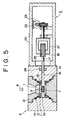
- Figure 5 is a sectional view of a crystallographic observation apparatus in a fourth embodiment according to the present invention;
- Figure 6 is a sectional view of a conventional crystallographic observation apparatus; and
- Figure 7 is a sectional view of an essential portion of another conventional crystallographic observation apparatus.
- Referring to Figure 1, a crystallographic observation apparatus comprises a
pressure vessel 3 in the form of a block having acavity 7, apressurizing device 4 for pressurizing thepressure vessel 3, and apressure pipe 6 connecting thepressurizing device 4 to thepressure vessel 3. Apipe 5 is connected to thepressurizing device 4 to supply apressure medium 15 to thepressurizing device 4. - The
pressure vessel 3 is provided with a first semispherical observation window block 1 and a second semisphericalobservation window block 2 respectively in the upper and lower side walls thereof. The first and second observation window blocks 1 and 2 are formed of sapphire and are held in place by observation windowblock holding members 12 with their flat circular surfaces facing thecavity 7 of thepressure vessel 3. The observation windowblock holding members 12 are screwed in thepressure vessel 3. O rings 13 are provided to seal the interfaces between the observation windowblock holding members 12 and thepressure vessel 3. The central portions of the spherical surfaces of the first and second observation window blocks 1 and 2 are flattened to enable the exact observation of a sample. - A small, transparent
elastic vessel 10 is formed entirely of silicon rubber. The flange of theelastic vessel 10 is pressed firmly against the periphery of the flat circular surface of the first observation window block 1 and the lower end of the observation windowblock holding member 12 by a fastening ring 11 screwed on the lower portion of the observation windowblock holding member 12 to form a pressure-tight sample chamber 9 defined by the first observation window block 1 and theelastic vessel 10. The sample is sealed in the sample chamber. The pressurizingdevice 4 is connected by apressure pipe 6 and a channel in the vessel wall to the interior of thepressure vessel 3, and a straingage pressure sensor 19 is provided on thepressure pipe 6. - The process of crystallization of a liquid sample was observed by the crystallographic observation apparatus. In observing the process of the crystallization of the liquid sample, the
pressure medium 15 was supplied by the pressurizingdevice 4 to thepressure vessel 3 to fill up thecavity 7. The liquid sample was illuminated through the secondobservation window block 2 by alight source 8 for observation by an optical microscope, not shown, disposed outside thepressure vessel 3 near the first observation window block 1. Then, thecavity 7 was pressurized by increasing the pressure of thepressure medium 15 filled in thecavity 7 by the pressurizingdevice 4 to apply increasing pressure to the liquid sample. As the internal pressure of thecavity 7 increased, theelastic vessel 10 was caused to contract gradually and crystals began to form in the liquid sample when the internal pressure of thecavity 7 reached the crystallization pressure. The crystallization pressure measured by the crystallographic observation apparatus was equal to that measured by the conventional crystallographic observation apparatus. - A sample having a pressure of fusion, the accurate value of which (hereinafter referred to as "reference value") is known, was subjected to the measurement of the pressure of fusion by the crystallographic observation apparatus. The
pressure medium 15 was supplied through thepressure pipe 6 to thepressure vessel 3 by the pressurizingdevice 4 to fill up thecavity 7 of thepressure vessel 3 with thepressure medium 15 and the sample was illuminated through the secondobservation window block 2 by thelight source 8. The condition of the sample was observed through the first observation window block 1. - Then, the pressure of the
pressure medium 15 filled in thecavity 7 was increased gradually by the pressurizingdevice 4 to apply pressure to the sample. Theelastic vessel 10 contracted gradually as the pressure of thepressure medium 15 was increased. The internal pressure of thesample chamber 9 was measured by the straingage pressure sensor 19 provided on thepressure pipe 6. The internal pressure of thesample chamber 9 was increased to a level where the sample was solidified, and then the internal pressure of thesample chamber 9 was decreased gradually. While the internal pressure of thesample chamber 9 was being decreased, the internal pressure of the sample chamber was measured continuously by the straingage pressure sensor 19 and the condition of the sample was observed. The measured pressure of fusion thus determined was higher than the reference value only by 0.2% of the reference value. This measured pressure of fusion is very accurate as compared with that measured by the conventional crystallographic observation apparatus, which is higher than the reference value by 2.5% of the reference value. - A crystallographic observation apparatus in a second embodiment according to the present invention is substantially the same in construction and function as the crystallographic observation apparatus in the first embodiment, except that a pressure vessel employed in the second embodiment is provided with only one observation window block 1, and an opaque
elastic vessel 10 is employed. The crystallographic observation apparatus in the second embodiment employs a reflection optical microscope instead of a transmission optical microscope for the observation of the sample. The performance of this crystallographic observation apparatus was the same as that of the foregoing crystallographic observation apparatus in the first embodiment. - A crystallographic observation apparatus in a third embodiment according to the present invention is substantially the same in construction and function as the crystallographic observation apparatus in the first embodiment, except that a
pressure vessel 3 employed in the third embodiment is provided with only one observation window block 1, and a small, transparentelastic capsule 10 is employed for containing a sample. The crystallographic observation apparatus in the third embodiment employs a reflection optical microscope instead of a transmission optical microscope for the observation of the sample. The upper wall of theelastic capsule 10 facing the observation window block 1 is formed of a transparent material and the rest of the walls are formed of an opaque elastic material. - The satisfactory performance of the crystallographic observation apparatus in the observation of the sample and in the measurement of the pressure of fusion of the sample was the same as that of the crystallographic apparatus in the first embodiment.
- Referring to Fig. 5, a crystallographic observation apparatus in a fourth embodiment according to the present invention comprises a
pressure vessel 3 having acavity 7, and apressurizing device 4 directly connected to thepressure vessel 3. Thepressure vessel 3 is substantially the same in construction and configuration as that of the crystallographic observation apparatus in the third embodiment, and hence the description thereof will be omitted to avoid duplication. - The pressurizing
device 4 comprises aplunger 17 fitted in a throughhole 16 formed in oneside wall 14 of thepressure vessel 3 so as to communicate with thecavity 7 of thepressure vessel 3, and adriving mechanism 20 for driving theplunger 17. Indicated at 24 is a pressure-tight sealing member. - The
driving mechanism 20 comprises anelectric motor 23, aworm reduction gear 22 having a worm fixedly mounted on the output shaft of theelectric motor 23 and a worm wheel engaging the worm and fixedly mounted on one end of a driving shaft, and a screw-nut pressing mechanism comprising an internally threadedrotary member 21 attached to the other end of the driving shaft, and ascrew rod 18 engaging theinternal thread 25 of therotary member 21 and joined to theplunger 17. Theplunger 17 is driven for movement toward or away from thecavity 7 through theworm reduction gear 22 and the screw-nut pressing mechanism by theelectric motor 23 to apply pressure to or to relieve pressure from apressure medium 15 filling up thecavity 7 and the throughhole 16. - A small,
elastic capsule 10 for containing a sample is formed entirely of transparent silicon rubber. A sample is contained in thesample chamber 9 of theelastic capsule 10. - In observing the condition of the sample contained in the
elastic capsule 10 placed in thecavity 7 of thepressure vessel 3, the sample is illuminated through the observation window block 1 by alight source 8, thepressure medium 15 is filled in thecavity 7 and the throughhole 16, and then theplunger 17 is advanced by theelectric motor 23 to apply pressure to the sample contained in thesample chamber 9 of theelastic capsule 10 by pressurizing thepressure medium 15 filled in thecavity 7 and the throughhole 16. The condition of the sample under pressure is observed with an optical microscope, not shown, through the observation window block 1. - In determining the crystallization pressure and pressure of fusion of the sample, a pressure at which crystallization occurs is determined while the pressure in the
cavity 4 is increased to a high pressure level where the sample is solidified, and the pressure of fusion is determined while the pressure is decreased gradually from the high pressure level. - The practical operation of the crystallographic observation apparatus showed that the performance of the crystallographic observation apparatus in the fourth embodiment in determining the crystallization pressure and the pressure of fusion is the same as those of the foregoing embodiments.
- The
worm reduction gear 22 may be driven by a manual driving mechanism instead of theelectric motor 23. However, the use of theelectric motor 23 for driving theworm reduction gear 22 makes possible discretionary pressure control, pressurization at a constant rate and employment of a computer for complicated pressure regulation. - This crystallographic observation apparatus needs a comparatively small amount of pressure medium necessary for filling up only the
cavity 7 and the throughhole 16, so that the pressurizingdevice 4 may be of a comparatively small capacity or the pressure medium can be pressurized or the pressure applied to the pressure medium can be decreased in a comparatively short time. - Since the
pressurizing device 4 is connected directly to thepressure vessel 3 omitting a pressure pipe and the pressurizing system employing theplunger 17 is inherently resistant to the leakage of the pressure medium, there is the least possibility of the leakage of the pressure medium. - Since the
pressurizing device 4 is connected directly to thepressure vessel 3 without using any pipe, theplunger 17 is fitted in the throughhole 16 formed in theside wall 14 of thepressure vessel 3, and only the driving mechanism is disposed outside thepressure vessel 3, the crystallographic observation apparatus including the pressuring device can be formed in a compact construction. - As is apparent from the foregoing description, the crystallographic observation apparatus in accordance with the present invention requires a comparatively small amount of sample, facilitates the placement of the sample in the cavity of the pressure vessel, enables the placement of the sample in the cavity of the pressure vessel in a comparatively short time, is capable of accurately regulating the pressure applied to the sample, eliminates heating the sample in introducing the sample in the cavity of the pressure vessel, is capable of being washed comparatively easily for the subsequent observation of the next sample, and enables the microscope to be disposed with the objective lens thereof at a comparatively short distance from the sample for the observation of the sample at a high magnification.
Claims (12)
- A high-pressure crystallographic observation apparatus comprising:
a pressure vessel (3) having a cavity (7) and provided with a transparent observation window block (1) in the vessel wall; and
pressurizing means (4) for pressurizing the cavity of the pressure vessel;
characterised by a feed channel in the vessel wall connecting said pressurizing means to said vessel cavity,
and a small elastic sample containing means (10) for containing a sample, sealed within the cavity (7) of the pressure vessel (3). - A high-pressure crystallographic observation apparatus according to Claim 1, characterised in that the pressure vessel is provided with transparent observation window blocks (1,2) respectively in opposite walls thereof.
- A high-pressure crystallographic observation apparatus according to claim 2, characterised in that two window blocks (1, 2) are provided in oppositely facing walls of the cavity (7) and the small elastic sample containing means is transparent or provided with two respective transparent windows, and photometric means is provided near one of the window blocks to measure the intensity of light transmitted through the sample from a light source provided at the other window block.
- A high-pressure crystallographic observation according to Claim 1, characterised in that the pressure vessel is provided with a transparent observation window block in one side.
- A high-pressure crystallographic observation apparatus according to claim 4, characterised in that said small elastic sample containing means is provided with a transparent window in the wall thereof facing the transparent observation window block of said pressure vessel.
- A high-pressure crystallographic observation apparatus according to any one of claims 1 to 5, characterised in that said sample containing means defines the sample chamber together with one of the transparent window blocks.
- A high-pressure crystallographic observation apparatus according to any one of claims 1 to 5, characterised in that said sample containing means is a capsule completely enclosing the sample.
- A high-pressure crystallographic observation apparatus according to any one of claims 1 to 7, characterised by pressure measuring means (19) for measuring the pressure acting on the sample contained in the small elastic sample containing means.
- A high-pressure crystallographic observation apparatus according to any one of claims 1 to 8, characterised in that each transparent observation window block has a semispherical shape and is disposed with the flat circular surface thereof facing the cavity of the pressure vessel.
- A high-pressure crystallographic observation apparatus according to any one of claims 1 to 9, characterised in that said pressurizing means comprises a plunger fitted in a through hole formed in the side wall of said pressure vessel so as to communicate with the cavity, and driving means for driving the plunger for axial movement toward or away from the cavity.
- A high-pressure crystallographic observation apparatus according to any one of claims 1 to 10, characterised by image pickup means disposed near the transparent observation window block, display means for displaying the image of the sample taken by the image pickup means, and indicating means for indicating numerical data representing the pressure acting on the sample and the temperature of the sample on the display means.
- A high-pressure crystallographic observation apparatus according to claim 10, characterised by recording means for recording the image of the sample taken by said image pickup means.
Applications Claiming Priority (6)
| Application Number | Priority Date | Filing Date | Title |
|---|---|---|---|
| JP4907589A JP2502361B2 (en) | 1989-01-10 | 1989-02-28 | Melting pressure measuring device and melting pressure measuring method |
| JP49075/89 | 1989-02-28 | ||
| JP49074/88 | 1989-02-28 | ||
| JP1049074A JPH0833341B2 (en) | 1988-12-15 | 1989-02-28 | Simple container type crystal observation device |
| JP24780089A JP2655917B2 (en) | 1989-09-22 | 1989-09-22 | Crystal observation device |
| JP247800/89 | 1989-09-22 |
Publications (3)
| Publication Number | Publication Date |
|---|---|
| EP0385035A2 EP0385035A2 (en) | 1990-09-05 |
| EP0385035A3 EP0385035A3 (en) | 1992-01-02 |
| EP0385035B1 true EP0385035B1 (en) | 1994-05-11 |
Family
ID=27293511
Family Applications (1)
| Application Number | Title | Priority Date | Filing Date |
|---|---|---|---|
| EP89312958A Expired - Lifetime EP0385035B1 (en) | 1989-02-28 | 1989-12-12 | High-pressure crystallographic observation apparatus |
Country Status (3)
| Country | Link |
|---|---|
| US (1) | US5082635A (en) |
| EP (1) | EP0385035B1 (en) |
| DE (1) | DE68915264T2 (en) |
Families Citing this family (14)
| Publication number | Priority date | Publication date | Assignee | Title |
|---|---|---|---|---|
| US5277746A (en) * | 1992-07-27 | 1994-01-11 | Texas Instruments Incorporated | High pressure liquid phase epitaxy reactor chamber and method with direct see through capability |
| JP2818533B2 (en) * | 1993-08-10 | 1998-10-30 | 動力炉・核燃料開発事業団 | Separation and purification method of spent solvent generated from nuclear fuel cycle |
| JPH0834699A (en) * | 1994-07-25 | 1996-02-06 | Fujitsu Ltd | Biopolymer crystallizer |
| FR2724457B1 (en) * | 1994-09-09 | 1996-12-13 | Inst Francais Du Petrole | DEVICE FOR TAKING THERMODYNAMIC MEASUREMENTS ON POLYPHASIC FLUIDS AT VERY HIGH PRESSURES AND TEMPERATURES |
| DE10059751B4 (en) * | 2000-11-30 | 2004-09-30 | Leuze Lumiflex Gmbh + Co. Kg | Method and circuit arrangement for checking an output of an electrical component |
| US6604852B1 (en) * | 2000-12-09 | 2003-08-12 | Halliburton Energy Services, Inc. | High pressure brine crystallization point apparatus |
| BE1015081A3 (en) * | 2002-08-26 | 2004-09-07 | Orfit Ind | Determining crystallisation characteristics of polymer material objects e.g. oriented films or fibres, by measuring internal crimp force exerted on holder used to stretch molten object |
| US7224475B2 (en) * | 2004-04-29 | 2007-05-29 | Battelle Energy Alliance, Llc | Methods and apparatus for measurement of a dimensional characteristic and methods of predictive modeling related thereto |
| GB2438838A (en) * | 2006-06-08 | 2007-12-12 | Patricia Lebre Alireza | Miniature High Pressure Cell for Sample Characterization. |
| US20080202215A1 (en) * | 2007-02-22 | 2008-08-28 | M-I L.L.C. | Pressurized crystallization point automated test apparatus |
| US20080202214A1 (en) * | 2007-02-22 | 2008-08-28 | M-I L.L.C. | Crystallization point automated test apparatus |
| GB2527545B (en) * | 2014-06-25 | 2018-02-07 | International Moisture Analysers Ltd | Sight glass apparatus |
| DE102014018858B3 (en) * | 2014-12-15 | 2015-10-15 | Alfred-Wegener-Institut Helmholtz-Zentrum für Polar- und Meeresforschung | High-pressure resistant sample chamber for transmitted light microscopy and method for its production |
| AT527117B1 (en) * | 2023-07-25 | 2024-11-15 | Hot Microfluidics Gmbh | high-pressure viewing cell for microfluid applications |
Family Cites Families (13)
| Publication number | Priority date | Publication date | Assignee | Title |
|---|---|---|---|---|
| NL63276C (en) * | 1941-04-04 | |||
| LU37663A1 (en) * | 1955-08-29 | |||
| US3206279A (en) * | 1961-09-18 | 1965-09-14 | Eastman Kodak Co | Lanthanum fluoride infrared transmitting optical elements |
| US3291575A (en) * | 1965-01-27 | 1966-12-13 | Sawyer Res Products Inc | Method for growth of pegmatitic quartz crystals in a controlled axial direction |
| US3741656A (en) * | 1971-05-27 | 1973-06-26 | Bendix Corp | Fill level measuring device |
| US3825242A (en) * | 1971-08-05 | 1974-07-23 | Little Inc A | Apparatus for direct melt syhthesis of intermetallic compounds |
| US4074939A (en) * | 1973-12-19 | 1978-02-21 | Max-Planck-Gesellschaft Zur Foerderung Der Wissenschaften E.V. | Apparatus for investigating fast chemical reactions by optical detection |
| US4512846A (en) * | 1982-01-26 | 1985-04-23 | The United States Of America As Represented By The Administrator Of The National Aeronautics And Space Administration | Method for growth of crystals by pressure reduction of supercritical or subcritical solution |
| DE3424108A1 (en) * | 1984-06-29 | 1986-01-09 | Bernhard Prof. Dr.-Ing. 4300 Essen Schrader | SPECTROMETRY SAMPLE ARRANGEMENT, METHOD FOR MEASURING LUMINESCENCE AND SCATTERING AND USE OF THE SAMPLE ARRANGEMENT |
| US4715711A (en) * | 1985-10-18 | 1987-12-29 | Chevron Research Company | Miniature sapphire anvil cell for reservoir fluid property studies |
| JPS63182003A (en) * | 1987-01-21 | 1988-07-27 | Kobe Steel Ltd | Pressure crystallization system for raw material of high concentration and pressure crystallization method |
| JPS63218105A (en) * | 1987-03-05 | 1988-09-12 | 三菱電線工業株式会社 | Aerial insulated wire |
| JPH0640923B2 (en) * | 1987-03-05 | 1994-06-01 | 軽質留分新用途開発技術研究組合 | Pressure cooling crystallization method and equipment |
-
1989
- 1989-12-11 US US07/448,287 patent/US5082635A/en not_active Expired - Lifetime
- 1989-12-12 DE DE68915264T patent/DE68915264T2/en not_active Expired - Fee Related
- 1989-12-12 EP EP89312958A patent/EP0385035B1/en not_active Expired - Lifetime
Also Published As
| Publication number | Publication date |
|---|---|
| US5082635A (en) | 1992-01-21 |
| DE68915264D1 (en) | 1994-06-16 |
| EP0385035A2 (en) | 1990-09-05 |
| DE68915264T2 (en) | 1994-09-08 |
| EP0385035A3 (en) | 1992-01-02 |
Similar Documents
| Publication | Publication Date | Title |
|---|---|---|
| US5082635A (en) | High-pressure crystallographic observation apparatus | |
| Randzio et al. | An isothermal scanning calorimeter controlled by linear pressure variations from 0.1 to 400 MPa. Calibration and comparison with the piezothermal technique | |
| US4644782A (en) | Spinning rod interfacial tensiometer | |
| Gregg et al. | A variable-volume optical pressure-volume-temperature cell for high-pressure cloud points, densities, and infrared spectra, applicable to supercritical fluid solutions of polymers up to 2 kbar | |
| GB2267577A (en) | Capillary viscosimeter. | |
| US3518875A (en) | Osmometer | |
| JP2502361B2 (en) | Melting pressure measuring device and melting pressure measuring method | |
| US6675643B2 (en) | Container volume measuring device and method | |
| US5172977A (en) | Isobaric dilatometer | |
| JPH0833341B2 (en) | Simple container type crystal observation device | |
| KR20030061746A (en) | Blood cell rheometer | |
| US4658637A (en) | Cell for analyzing a fluid which is condensable, at least in part | |
| Mazuruk et al. | Viscosity of Hg0. 84Zn0. 16Te pseudobinary melt | |
| Buisine et al. | Phase transition under pressure of two disc-like liquid crystals studied with an accurate automated metabolemeter | |
| US2448768A (en) | Method and apparatus for measuring surface tension | |
| RU2858411C1 (en) | Device for controlling piston positioning within pvt unit | |
| JPH04102046A (en) | Optical measuring apparatus | |
| WO2006115601A2 (en) | Nanoliter osmometer and method of operation | |
| JP2655917B2 (en) | Crystal observation device | |
| SU887890A1 (en) | Cruostat for investigating shape memoryg effect | |
| Wahl | IV. Physico-chemical determinations at high pressures by optical methods | |
| US3417622A (en) | Pressure gauge | |
| EP1693488B1 (en) | Lens and optical electronic device | |
| JP2025101923A (en) | Swelling test device and swelling test method | |
| Vinš et al. | Improvements of the experimental apparatus for measurement of the surface tension of supercooled liquids using horizontal capillary tube |
Legal Events
| Date | Code | Title | Description |
|---|---|---|---|
| PUAI | Public reference made under article 153(3) epc to a published international application that has entered the european phase |
Free format text: ORIGINAL CODE: 0009012 |
|
| 17P | Request for examination filed |
Effective date: 19891221 |
|
| AK | Designated contracting states |
Kind code of ref document: A2 Designated state(s): DE FR GB |
|
| PUAL | Search report despatched |
Free format text: ORIGINAL CODE: 0009013 |
|
| AK | Designated contracting states |
Kind code of ref document: A3 Designated state(s): DE FR GB |
|
| 17Q | First examination report despatched |
Effective date: 19920225 |
|
| GRAA | (expected) grant |
Free format text: ORIGINAL CODE: 0009210 |
|
| AK | Designated contracting states |
Kind code of ref document: B1 Designated state(s): DE FR GB |
|
| REF | Corresponds to: |
Ref document number: 68915264 Country of ref document: DE Date of ref document: 19940616 |
|
| ET | Fr: translation filed | ||
| PLBE | No opposition filed within time limit |
Free format text: ORIGINAL CODE: 0009261 |
|
| STAA | Information on the status of an ep patent application or granted ep patent |
Free format text: STATUS: NO OPPOSITION FILED WITHIN TIME LIMIT |
|
| 26N | No opposition filed | ||
| REG | Reference to a national code |
Ref country code: GB Ref legal event code: IF02 |
|
| PGFP | Annual fee paid to national office [announced via postgrant information from national office to epo] |
Ref country code: GB Payment date: 20031210 Year of fee payment: 15 Ref country code: FR Payment date: 20031210 Year of fee payment: 15 |
|
| PGFP | Annual fee paid to national office [announced via postgrant information from national office to epo] |
Ref country code: DE Payment date: 20031229 Year of fee payment: 15 |
|
| PG25 | Lapsed in a contracting state [announced via postgrant information from national office to epo] |
Ref country code: GB Free format text: LAPSE BECAUSE OF NON-PAYMENT OF DUE FEES Effective date: 20041212 |
|
| PG25 | Lapsed in a contracting state [announced via postgrant information from national office to epo] |
Ref country code: DE Free format text: LAPSE BECAUSE OF NON-PAYMENT OF DUE FEES Effective date: 20050701 |
|
| GBPC | Gb: european patent ceased through non-payment of renewal fee |
Effective date: 20041212 |
|
| PG25 | Lapsed in a contracting state [announced via postgrant information from national office to epo] |
Ref country code: FR Free format text: LAPSE BECAUSE OF NON-PAYMENT OF DUE FEES Effective date: 20050831 |
|
| REG | Reference to a national code |
Ref country code: FR Ref legal event code: ST |