EP0383894B1 - Ventilation valve - Google Patents
Ventilation valve Download PDFInfo
- Publication number
- EP0383894B1 EP0383894B1 EP89909770A EP89909770A EP0383894B1 EP 0383894 B1 EP0383894 B1 EP 0383894B1 EP 89909770 A EP89909770 A EP 89909770A EP 89909770 A EP89909770 A EP 89909770A EP 0383894 B1 EP0383894 B1 EP 0383894B1
- Authority
- EP
- European Patent Office
- Prior art keywords
- louvre
- component
- ventilation valve
- flow
- valve according
- Prior art date
- Legal status (The legal status is an assumption and is not a legal conclusion. Google has not performed a legal analysis and makes no representation as to the accuracy of the status listed.)
- Revoked
Links
- 238000009423 ventilation Methods 0.000 title claims abstract description 57
- 230000003467 diminishing effect Effects 0.000 claims abstract description 8
- 230000003068 static effect Effects 0.000 claims description 3
- 238000011144 upstream manufacturing Methods 0.000 claims description 3
- 238000005259 measurement Methods 0.000 description 7
- 230000033001 locomotion Effects 0.000 description 4
- 238000000926 separation method Methods 0.000 description 3
- 238000007789 sealing Methods 0.000 description 2
- 239000003566 sealing material Substances 0.000 description 2
- 230000005540 biological transmission Effects 0.000 description 1
- 238000010586 diagram Methods 0.000 description 1
- 230000003670 easy-to-clean Effects 0.000 description 1
- 235000000396 iron Nutrition 0.000 description 1
- 238000004519 manufacturing process Methods 0.000 description 1
- 239000000463 material Substances 0.000 description 1
- 239000002184 metal Substances 0.000 description 1
- 238000005192 partition Methods 0.000 description 1
- 230000001360 synchronised effect Effects 0.000 description 1
Images


Classifications
-
- F—MECHANICAL ENGINEERING; LIGHTING; HEATING; WEAPONS; BLASTING
- F24—HEATING; RANGES; VENTILATING
- F24F—AIR-CONDITIONING; AIR-HUMIDIFICATION; VENTILATION; USE OF AIR CURRENTS FOR SCREENING
- F24F13/00—Details common to, or for air-conditioning, air-humidification, ventilation or use of air currents for screening
- F24F13/08—Air-flow control members, e.g. louvres, grilles, flaps or guide plates
- F24F13/10—Air-flow control members, e.g. louvres, grilles, flaps or guide plates movable, e.g. dampers
Definitions
- the present invention concerns a ventilation valve, comprising a first louvre component and a second louvre component, at least one of them being movable linearly for diminishing or enlarging the flow gap between said louvre components.
- US 4653384 shows an air supply adjusting mechanism for an air conditioner, in which two louvre components are provided with an air flow gap defined between them.
- the louvre components are mounted for independent pivotal motion to adjust the flow gap geometry.
- Ventilation valves are known in the art in which the ventilation valve is composed of two section parts, that is, of adjustment louvres which can be moved relative to one another.
- the flow cross-section between the louvre components increases in the flow direction. The best possible passage for the air is not guaranteed by said arrangement.
- GB 1537167 shows an air exhaust ventilating device comprising two louvre components with a flow gap defined between them which increases in flow cross-section in the direction of the air flow.
- the aim of the invention is a ventilation valve comprising an extensive adjustment area, enabling the use of a device of the same order for different targets.
- the objective of the invention is specifically a ventilation valve in which measurement and adjustment are easy.
- the aim of the invention is a ventilation valve in which the aerodynamic properties are advantageous and resonance phenomena have been avoided.
- the present invention provides a ventilation valve, comprising a first louvre component and a second louvre component, each louvre component comprising a first curved surface portion upstream of the flow and a second surface portion downstream of the first curved surface portion, at least the second louvre component being moveable for altering the size of a flow gap between the louvre components, characterized in that said second surface portion is at an angle relative to the central axis of the flow gap of the ventilation valve, the second curved surface portion of each louvre component being connected to a curved surface section adjacent the trailing part of the flow, and to the first surface portion, and in that the flow gap comprises an elongate gap defined between the louvre components, the flow gap diminishing in flow cross-sectional area in the direction of flow and the movable louvre component being moveable linearly for diminishing or enlarging the flow gap.
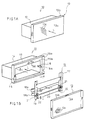
- Fig. 1A presents in axonometric image the ventilation valve of the invention when assembled.
- Fig. 1B presents in axonometric image the ventilation valve of the invention with the detachable basic components depicted in separation.
- Fig. 2 presents in axonometric image the ventilation valve of the invention with the front cover plate removed.
- Fig. 3A presents in principle view the ventilation valve of the invention.
- the image is taken primarily along the section line I-I of Fig. 2, and the image has been simplified with reference to Fig. 2.
- the operational position of a valve implementing the maximal air flow is presented.
- Fig. 3B presents the valve of Fig. 3a in the operational position implementing the minimal air flow.
- Fig. 4 presents the operational graphs of the ventilation valve.
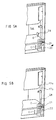
- Fig. 5A presents a first advantageous location of the adjustment scale.
- Fig. 5B presents a second advantageous location of the adjustment scale.
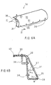
- Fig. 6A presents the louvre component in axonometric image.
- Fig. 6B presents section II-II of Fig. 6A.
- Fig. 1A is presented the ventilation valve 10 of the invention in assembled form.
- the direction of the air flow is indicated by arrow L.
- the ventilation valve 10 comprises an envelope part 11 to which the front cover 13 has been attached.
- the front cover comprises the front part 13a and edges 13b.
- the entire front cover 13 has advantageously been constructed of a similar structure and comprises flow apertures 13c being in shape e.g. gaps, slots, holes, etc.
- the front cover 13 may also be composed of a structure which comprises a planar, non-apertured plate section in front of the louvre components.
- the flow gap or gaps are hereby defined between the edges of the plate part and the collar of the envelope part 11.
- the front cover 13 may be attached to the envelope part 11 by projecting irons or by equivalent arrangements.
- Fig. 1B a ventilation valve with the detachable central components being depicted in separation.
- the ventilation valve comprises an envelope part 11 and an adjustment component 12 attachable thereto, and furthermore, a detachable front cover part 13.
- the envelope part 11 comprises a duct part 14, enclosing thereinside a flow duct A1.
- the flow passage direction is indicated also in Figs 1A and 1B by arrow L.
- the envelope 11 comprises a collar part 15 at one end of the duct part 14.
- the collar part comprises an edge 15a, its plane being in the direction of the longitudinal axis X of the duct.
- the collar part 15 also comprises a bottom part 15b which in plane is perpendicular to the longitudinal axis X of the duct portion 14.
- On top of the bottom part 15b is placed a sealing material layer 15c.
- the inner surface 14a of the duct part 14 comprises attaching means 16 attached thereto.
- attaching means 16 There are two pieces of said attaching means 16 and they form a hook-like endface part 16a with the aid of which the bodyparts 17 of the adjustment part 12 are compressed against the sealing material layer 15c.
- the attaching means 16 may be made of an elastic plate material and they may be advantageously attached to the duct part 14 with rivets.
- the adjustment part 12 As shown in Fig. 1B, the adjustment part 12 attached to the envelope part 11 with the attaching means 16 has been placed in separation from the envelope part 11.
- the adjustment part 12 comprises two bodyparts 17.
- the bodypart 17 is advantageously an L-shaped section, comprising, when the adjustment part 12 is set in place, a plate component 17a in the direction of the X axis of the envelope part 11 and a plate component 17b at 90° angle relative to the plate component 17a connected thereto.
- the plate component 17b is perpendicular in plane to the X axis.
- the adjustment part 12 comprises a first louvre component, that is, section 18a, and a second component, that is, section 18b.
- a first louvre component that is, section 18a
- a second component that is, section 18b.
- the louvre component 18b is movable, as shown in Fig. 1B, by arrow C.
- the louvre component 18b is movable linearly.
- only one of the louvre components 18 can be moved.
- both of the louvre components are movable relative to one another.
- the location adjustment means 19 of the movable louvre component 18b comprises a rod 20 provided at both ends with drive wheels 21, advantageously gears.
- the rod 20 may be a hexagonal section rod, whereby it can be turned with a spanner.
- the drive wheels 21 are engaged on the abutment surface 22 of the louvre part 18b.
- the drive wheel 21 is a gear and the abutment surface 22 is together with the gear 21 an interacting serration 22.
- the purpose of the rod 20 is to act as a synchronizing rod. With the aid of the rod 20 both ends of the movable louvre component 18b are moved simultaneously.
- a flow gap A2 Between the first louvre component 18a and the second louvre component 18b is defined a flow gap A2. Said flow gap tapers relative to the incoming direction L of the air flow. Said flow gap A2 is adjusted by moving the louvre component 18b linearly with the location adjustment means 19 as is shown by arrow c.
- Fig. 2 is presented more in detail the ventilation valve of the invention.
- Fig. 2 is presented the movable louvre component 18b and the devices engaged thereto in order to implement the linear adjustment movement.
- the location adjustment means 19 comprises an attachment plate 23 attached to the bodypart 17, on its plate section 17a.
- the plate 23 has a hole 24 through which the rod 20 has been disposed to pass.
- the attachment plate 23 serves at the same time as the bearing point for the rod 20.
- the ends of the rod 20 have been disposed to pass in the body 17 through the hole 25 located in its plate section 17a.
- the end of the rod 20 is provided with a notch 26 into which an end of a tool, such as of a screw driver, can be fitted for turning the rod 20 and for moving the section 18b.
- the envelope part 11 has furthermore a notch 27 on the edge part 15a of the collar 15 through which a tool may be fixed to the rod 20.
- the drive wheel 21 By turning the rod 20 the drive wheel 21 is rotated, this being operationally connected to the abutment surface 22 being fixedly attached to the louvre 18b, said abutment surface being advantageously a straight abutment surface.
- the drive wheel 21 is a gear and the abutment surface 22 is a gearrack. Said parts are advantageously made of plastic.
- the abutment stop face 22 is furthermore pressed against the plate section 17b of the body 17 and it can be moved in conformance to said even plate part.
- the abutment stop part 22 may furthermore comprise a separate plate part engaged to the other side of the plate section 17b of the body 17, ensuring the maintaining of the louvre component 18b on the body 17 in all circumstances of use.
- the adjustment part 12 is connected to the body 17 with an attaching member 16.
- the attaching member 16 presses the body 17 fast to the envelope part 11.
- the louvre component 18a is in a fixed position on the body 17.
- the louvre component 18a comprises a fixing plate 29 through which a fixing member 30, for instance a rivet, has been taken and which fixing member is furthermore fixed to the body 17, to its plate section 17b.
- the louvre component 18b is moved linearly and the location of said louvre component can be read on the scale 28, which is advantageously a millimetre scale.
- the scale has been disposed on the inner surface 14a of the duct portion 14.
- a reduced image is presented of the ventilation valve of the invention and included primarily along the section line I-I of the figure.
- the louvre component 18b can be moved linearly.
- the louvre component 18b comprises a portion 31 with a straight surface guiding the air flow, said portion being in plane in angle ⁇ relative to the central axis X of the ventilation valve flow duct A2.
- the duct A2 tapers relative to the progression direction L of the air flow.
- the louvre component 18 comprises a smoothly curving preguiding surface 32 of the flow, which later joins the straight flange section 33, said flange section 33 being approximately perpendicular to the axis X.
- the flange section 33 acts as a mobile sealing component and enables the adjustment movement of the section and allows the passage of the air flow merely between the louvres 18b and 18a.
- Fig. 3A is presented an on-position of the ventilation valve in which the flow passage A2 is maximal.
- Fig. 3A the mobile louvre component 18b has been moved to a position implementing a minimal air flow, that is to a position in which the flow cross-section area A2 is minimal.
- arrow c presents the transfer of the mobile section 18b into the position of the ventilation valve implementing said minimal air flow.
- the louvres 18a and 18b are equivalent, and therefore, there is no need to manufacture more than one kind of louvres.
- the louvre components 18a and 18b have respectively been so attached to the structure that the main surfaces of the louvre components, or the surface portions 31, deviating the flow are at respective angle ⁇ relative to the central axis X of the flow duct A2.
- Angle ⁇ is advantageously in the range 3-15°.
- the surface portions 31 are advantageously straight surfaces, and hereby, the surface plane is at angle ⁇ relative to the central axis X of the flow duct A2.
- ⁇ is within the range 3-15°, advantageously about 7°.
- Fig. 4 the operation curves of the ventilation valves of the invention are presented. As taught by the invention, the operation diagram is used in Fig. 4 as follows. On the measurement scale is read the opening position and at the same time, the pressure across the ventilation valve is measured with a pressure connector to be described later. Thereafter, the volumetric flow corresponding to the opening position may be read on the curves.
- Fig. 5A is presented an advantageous positioning of the scale 28.
- the scale 28 is located on the inner wall 14a of the duct 14.
- the opening position is read at the edge E of the louvre 18b.
- the scale 28 has been disposed on the surface of the plate portion 17b of the body 17.
- the opening position may be read at the edge E.
- Fig. 6A is presented an embodiment of the louvre 18 in axonometric image.
- the louvre 18 comprises a hollow interior space 34. Into said space 34 the flow passages open through apertures 35 for transmitting the flow pressure to the measuring instrument. Several apertures 35 are provided in the adjacency of the trailing edge of the flow. They are located linearly in the section 18, and therefore, a reliable measurement result and average are obtained throughout the whole flow passage. From the distributing chamber 34 is arranged a connector 36 on to the pressure gauge. The connector 36 is normally closed and it is only in a measuring situation when the connector 36 is connected to the measuring instrument.
- Fig. 6B is presented a section II-II of Fig. 6A.
- Fig. 6A is presented moreover an embodiment in which the louvre 18 comprises an interior space 34 divided by a partition 37.
- a pressure connector 38 to a sensor.
- the pressure in a pressure measuring event is conducted directly through the apertures 35 to the collecting connector 36, and further to a measurement sensor. No distributing chamber is used here.
- the ventilation valve comprises a louvre portion 18 which is provided with a surface 32 guiding the flow, located foremost relative to the flow, and a second flow-guiding surface 31, advantageously a straight surface connected thereto.
- the flow gap A2 tapers, as taught by the invention, more sharply at the foremost flow surface.
- the louvre component of the invention comprises further a curved trailing edge 39 joining to the flow surface 31 of the centremost louvre.
- the ventilation valve of the invention may be installed on a ceiling or on a wall.
- the means may also be connected to pressure distributing boxes known in the art.
- the means of the invention is silent even at high volumetric flow ranges. No resonance occurs.
- the means is simple to dismantle and, therefore, it is easy to clean.
- the front plate 13 of the means is architectonically advantageous.
- the ends 40 of the louvres 18 form a sealing, whereby the variations of longitudinal measuring or setting tolerances are eliminated.
- the ventilation valve of the invention serves both as a ventilation valve and as a control part for the air flow.
- the air speed increases, and at the same time, due to the surface friction between the air flow and the louvre surface, an adequate static duct pressure is achieved, as regards the measurement. Therefore, when a sufficient measurement of the static pressure of the air flow is achieved, the adjustment can be accomplished for the means, and at the same time, the measurement of the air flow quantity of the room space. Consequently, no separate adjustment component is needed.
- Such ventilation valve is described above that is suitable for an exhaust air means.
- air is drawn off from the room space.
- the ventilation valve is used as an incoming air means.
- the louvres are so positioned relative to one another that the flow gap between the louvres in the flow direction of the air is again tapered.
- the front cover plate 13 in said embodiment is positioned in the air travelling direction after the tapering flow gap.
Landscapes
- Engineering & Computer Science (AREA)
- Chemical & Material Sciences (AREA)
- Combustion & Propulsion (AREA)
- Mechanical Engineering (AREA)
- General Engineering & Computer Science (AREA)
- Air-Flow Control Members (AREA)
Abstract
Description
- The present invention concerns a ventilation valve, comprising a first louvre component and a second louvre component, at least one of them being movable linearly for diminishing or enlarging the flow gap between said louvre components.
- US 4653384 shows an air supply adjusting mechanism for an air conditioner, in which two louvre components are provided with an air flow gap defined between them. The louvre components are mounted for independent pivotal motion to adjust the flow gap geometry.
- Ventilation valves are known in the art in which the ventilation valve is composed of two section parts, that is, of adjustment louvres which can be moved relative to one another. In prior art ventilation valves, the flow cross-section between the louvre components increases in the flow direction. The best possible passage for the air is not guaranteed by said arrangement.
- For example, GB 1537167 shows an air exhaust ventilating device comprising two louvre components with a flow gap defined between them which increases in flow cross-section in the direction of the air flow.
- The aim of the invention is a ventilation valve comprising an extensive adjustment area, enabling the use of a device of the same order for different targets. The objective of the invention is specifically a ventilation valve in which measurement and adjustment are easy. The aim of the invention is a ventilation valve in which the aerodynamic properties are advantageous and resonance phenomena have been avoided.
- The present invention provides a ventilation valve, comprising a first louvre component and a second louvre component, each louvre component comprising a first curved surface portion upstream of the flow and a second surface portion downstream of the first curved surface portion, at least the second louvre component being moveable for altering the size of a flow gap between the louvre components, characterized in that said second surface portion is at an angle relative to the central axis of the flow gap of the ventilation valve, the second curved surface portion of each louvre component being connected to a curved surface section adjacent the trailing part of the flow, and to the first surface portion, and in that the flow gap comprises an elongate gap defined between the louvre components, the flow gap diminishing in flow cross-sectional area in the direction of flow and the movable louvre component being moveable linearly for diminishing or enlarging the flow gap.
- The invention is described now referring to some advantageous embodiments of the invention presented in the figures of the accompanying drawings, to which, however, the invention is not intended to be exclusively confined.
- Fig. 1A presents in axonometric image the ventilation valve of the invention when assembled.
- Fig. 1B presents in axonometric image the ventilation valve of the invention with the detachable basic components depicted in separation.
- Fig. 2 presents in axonometric image the ventilation valve of the invention with the front cover plate removed.
- Fig. 3A presents in principle view the ventilation valve of the invention. The image is taken primarily along the section line I-I of Fig. 2, and the image has been simplified with reference to Fig. 2. The operational position of a valve implementing the maximal air flow is presented.
- Fig. 3B presents the valve of Fig. 3a in the operational position implementing the minimal air flow.
- Fig. 4 presents the operational graphs of the ventilation valve.
- Fig. 5A presents a first advantageous location of the adjustment scale.
- Fig. 5B presents a second advantageous location of the adjustment scale.
- Fig. 6A presents the louvre component in axonometric image.
- Fig. 6B presents section II-II of Fig. 6A.
- In Fig. 1A is presented the
ventilation valve 10 of the invention in assembled form. The direction of the air flow is indicated by arrow L. As shown in the figure, theventilation valve 10 comprises anenvelope part 11 to which thefront cover 13 has been attached. The front cover comprises thefront part 13a andedges 13b. Theentire front cover 13 has advantageously been constructed of a similar structure and comprisesflow apertures 13c being in shape e.g. gaps, slots, holes, etc. Thefront cover 13 may also be composed of a structure which comprises a planar, non-apertured plate section in front of the louvre components. The flow gap or gaps are hereby defined between the edges of the plate part and the collar of theenvelope part 11. In said design thefront cover 13 may be attached to theenvelope part 11 by projecting irons or by equivalent arrangements. - In Fig. 1B is presented a ventilation valve with the detachable central components being depicted in separation. The ventilation valve comprises an
envelope part 11 and anadjustment component 12 attachable thereto, and furthermore, a detachablefront cover part 13. - The
envelope part 11 comprises aduct part 14, enclosing thereinside a flow duct A₁. The flow passage direction is indicated also in Figs 1A and 1B by arrow L. Theenvelope 11 comprises acollar part 15 at one end of theduct part 14. The collar part comprises anedge 15a, its plane being in the direction of the longitudinal axis X of the duct. Thecollar part 15 also comprises abottom part 15b which in plane is perpendicular to the longitudinal axis X of theduct portion 14. On top of thebottom part 15b is placed a sealingmaterial layer 15c. - The
inner surface 14a of theduct part 14 comprises attaching means 16 attached thereto. There are two pieces of said attachingmeans 16 and they form a hook-like endface part 16a with the aid of which thebodyparts 17 of theadjustment part 12 are compressed against the sealingmaterial layer 15c. The attaching means 16 may be made of an elastic plate material and they may be advantageously attached to theduct part 14 with rivets. - As shown in Fig. 1B, the
adjustment part 12 attached to theenvelope part 11 with theattaching means 16 has been placed in separation from theenvelope part 11. Theadjustment part 12 comprises twobodyparts 17. Thebodypart 17 is advantageously an L-shaped section, comprising, when theadjustment part 12 is set in place, aplate component 17a in the direction of the X axis of theenvelope part 11 and aplate component 17b at 90° angle relative to theplate component 17a connected thereto. Theplate component 17b is perpendicular in plane to the X axis. - The
adjustment part 12 comprises a first louvre component, that is,section 18a, and a second component, that is,section 18b. In the embodiment of Figs 1A-1B thelouvre component 18b is movable, as shown in Fig. 1B, by arrow C. Thelouvre component 18b is movable linearly. - In this embodiment of the invention, only one of the
louvre components 18 can be moved. Within the scope of the invention also such an embodiment is conceivable in which both of the louvre components are movable relative to one another. - The location adjustment means 19 of the
movable louvre component 18b comprises arod 20 provided at both ends withdrive wheels 21, advantageously gears. By rotating therod 20, thedrive wheels 21 coupled fixedly to therod 20 are rotated. Therod 20 may be a hexagonal section rod, whereby it can be turned with a spanner. Thedrive wheels 21 are engaged on theabutment surface 22 of thelouvre part 18b. In the most advantageous embodiment of the invention, thedrive wheel 21 is a gear and theabutment surface 22 is together with thegear 21 an interactingserration 22. The purpose of therod 20 is to act as a synchronizing rod. With the aid of therod 20 both ends of themovable louvre component 18b are moved simultaneously. Hereby, the transmission movement is made to be so synchronized that both ends of the louvre component are moved an equivalent length. The flow gap defined between thelouvre components - Between the
first louvre component 18a and thesecond louvre component 18b is defined a flow gap A₂. Said flow gap tapers relative to the incoming direction L of the air flow. Said flow gap A₂ is adjusted by moving thelouvre component 18b linearly with the location adjustment means 19 as is shown by arrow c. - In Fig. 2 is presented more in detail the ventilation valve of the invention. In Fig. 2 is presented the
movable louvre component 18b and the devices engaged thereto in order to implement the linear adjustment movement. The location adjustment means 19 comprises anattachment plate 23 attached to thebodypart 17, on itsplate section 17a. Theplate 23 has ahole 24 through which therod 20 has been disposed to pass. Theattachment plate 23 serves at the same time as the bearing point for therod 20. Furthermore, the ends of therod 20 have been disposed to pass in thebody 17 through thehole 25 located in itsplate section 17a. The end of therod 20 is provided with anotch 26 into which an end of a tool, such as of a screw driver, can be fitted for turning therod 20 and for moving thesection 18b. - The
envelope part 11 has furthermore anotch 27 on theedge part 15a of thecollar 15 through which a tool may be fixed to therod 20. - By turning the
rod 20 thedrive wheel 21 is rotated, this being operationally connected to theabutment surface 22 being fixedly attached to thelouvre 18b, said abutment surface being advantageously a straight abutment surface. In the embodiment of Fig. 2 thedrive wheel 21 is a gear and theabutment surface 22 is a gearrack. Said parts are advantageously made of plastic. - The
abutment stop face 22 is furthermore pressed against theplate section 17b of thebody 17 and it can be moved in conformance to said even plate part. Theabutment stop part 22 may furthermore comprise a separate plate part engaged to the other side of theplate section 17b of thebody 17, ensuring the maintaining of thelouvre component 18b on thebody 17 in all circumstances of use. - As shown in Fig. 2, the
adjustment part 12 is connected to thebody 17 with an attachingmember 16. The attachingmember 16 presses thebody 17 fast to theenvelope part 11. - In the embodiment of the figure, the
louvre component 18a is in a fixed position on thebody 17. Thelouvre component 18a comprises a fixingplate 29 through which a fixingmember 30, for instance a rivet, has been taken and which fixing member is furthermore fixed to thebody 17, to itsplate section 17b. - With the adjustment means 19 the
louvre component 18b is moved linearly and the location of said louvre component can be read on thescale 28, which is advantageously a millimetre scale. In the embodiment presented in Fig. 2 the scale has been disposed on theinner surface 14a of theduct portion 14. - In Fig. 3A, a reduced image is presented of the ventilation valve of the invention and included primarily along the section line I-I of the figure. As shown in the figure, the
louvre component 18b can be moved linearly. Thelouvre component 18b comprises aportion 31 with a straight surface guiding the air flow, said portion being in plane in angle α relative to the central axis X of the ventilation valve flow duct A₂. As shown in Fig. 3A, the duct A₂ tapers relative to the progression direction L of the air flow. In addition, thelouvre component 18 comprises a smoothly curvingpreguiding surface 32 of the flow, which later joins thestraight flange section 33, saidflange section 33 being approximately perpendicular to the axis X. Theflange section 33 acts as a mobile sealing component and enables the adjustment movement of the section and allows the passage of the air flow merely between thelouvres - In Fig. 3A the
mobile louvre component 18b has been moved to a position implementing a minimal air flow, that is to a position in which the flow cross-section area A₂ is minimal. In Fig. 3B, arrow c presents the transfer of themobile section 18b into the position of the ventilation valve implementing said minimal air flow. - The
louvres louvre components surface portions 31, deviating the flow are at respective angle α relative to the central axis X of the flow duct A₂. Angle α is advantageously in the range 3-15°. Thesurface portions 31 are advantageously straight surfaces, and hereby, the surface plane is at angle α relative to the central axis X of the flow duct A₂. Hereby, α is within the range 3-15°, advantageously about 7°. - In Fig. 4, the operation curves of the ventilation valves of the invention are presented. As taught by the invention, the operation diagram is used in Fig. 4 as follows. On the measurement scale is read the opening position and at the same time, the pressure across the ventilation valve is measured with a pressure connector to be described later. Thereafter, the volumetric flow corresponding to the opening position may be read on the curves.
- In Fig. 5A is presented an advantageous positioning of the
scale 28. In the embodiment of Fig. 5A thescale 28 is located on theinner wall 14a of theduct 14. By moving thelouvre 18b the opening position is read at the edge E of thelouvre 18b. - In the embodiment of Fig. 5B the
scale 28 has been disposed on the surface of theplate portion 17b of thebody 17. By moving thelouvre component 18b, as shown by arrow c, the opening position may be read at the edge E. - In Fig. 6A is presented an embodiment of the
louvre 18 in axonometric image. Thelouvre 18 comprises a hollowinterior space 34. Into saidspace 34 the flow passages open throughapertures 35 for transmitting the flow pressure to the measuring instrument.Several apertures 35 are provided in the adjacency of the trailing edge of the flow. They are located linearly in thesection 18, and therefore, a reliable measurement result and average are obtained throughout the whole flow passage. From the distributingchamber 34 is arranged aconnector 36 on to the pressure gauge. Theconnector 36 is normally closed and it is only in a measuring situation when theconnector 36 is connected to the measuring instrument. - In Fig. 6B is presented a section II-II of Fig. 6A. In Fig. 6A is presented moreover an embodiment in which the
louvre 18 comprises aninterior space 34 divided by apartition 37. Hereby, from the space 34a is provided apressure connector 38 to a sensor. - It is feasible to produce within the scope of the invention also the other structures of the
louvre components 18. A section component made of sheet metal may also be used. - Hereby, the pressure in a pressure measuring event is conducted directly through the
apertures 35 to the collectingconnector 36, and further to a measurement sensor. No distributing chamber is used here. - The trailing
edges 39 of thelouvres 18 are rounded. Said trailingedge 39 must not be sharp because that will cause turbulence, neither is excessive rounding desirable because that also causes turbulence. Therefore, as taught by the invention, the ventilation valve comprises alouvre portion 18 which is provided with asurface 32 guiding the flow, located foremost relative to the flow, and a second flow-guidingsurface 31, advantageously a straight surface connected thereto. The flow gap A₂ tapers, as taught by the invention, more sharply at the foremost flow surface. The louvre component of the invention comprises further acurved trailing edge 39 joining to theflow surface 31 of the centremost louvre. - The ventilation valve of the invention may be installed on a ceiling or on a wall. The means may also be connected to pressure distributing boxes known in the art. The means of the invention is silent even at high volumetric flow ranges. No resonance occurs. The means is simple to dismantle and, therefore, it is easy to clean. The
front plate 13 of the means is architectonically advantageous. - The ends 40 of the
louvres 18 form a sealing, whereby the variations of longitudinal measuring or setting tolerances are eliminated. - The ventilation valve of the invention serves both as a ventilation valve and as a control part for the air flow. As taught by the invention, with the tapering duct, and particularly, with said tapering in the air flow direction are obtained the following advantages. The air speed increases, and at the same time, due to the surface friction between the air flow and the louvre surface, an adequate static duct pressure is achieved, as regards the measurement. Therefore, when a sufficient measurement of the static pressure of the air flow is achieved, the adjustment can be accomplished for the means, and at the same time, the measurement of the air flow quantity of the room space. Consequently, no separate adjustment component is needed.
- Such ventilation valve is described above that is suitable for an exhaust air means. Thus, through said ventilation valve, as shown in the figures related to the embodiments described, air is drawn off from the room space. Such embodiment is also feasible within the scope of the invention in which the ventilation valve is used as an incoming air means. In said embodiment the louvres are so positioned relative to one another that the flow gap between the louvres in the flow direction of the air is again tapered. The
front cover plate 13 in said embodiment is positioned in the air travelling direction after the tapering flow gap.
Claims (15)
- A ventilation valve (10), comprising a first louvre component (18a) and a second louvre component (18b), each louvre component (18a, 18b) comprising a first curved surface portion (32) upstream of the flow and a second surface portion (31) downstream of the first curved surface portion (32), at least the second louvre component (18b) being moveable for altering the size of a flow gap (A₂) between the louvre components (18a, 18b), characterized in that said second surface portion (31) is at an angle (α) relative to the central axis (X) of the flow gap (A₂) of the ventilation valve (10), the second surface portion (31) of each louvre component (18) being connected to a curved surface section (39) adjacent the trailing part of the flow, and to the first surface portion (32), and in that the flow gap (A₂) comprises an elongate gap (A₂) defined between the louvre components (18a, 18b), the flow gap (A₂) diminishing in flow cross-sectional area in the direction of flow and the movable louvre component (18b) being moveable linearly for diminishing or enlarging the flow gap (A₂).
- Ventilation valve according to Claim 1, characterized in that the ventilation valve (10) comprises an elongated gap (A₂) formed between the louvre components (18a, 18b) which diminishes in cross-section at a greater rate upstream of the flow than downstream of the flow.
- Ventilation valve according to Claim 1 or 2, characterized in that the ventilation valve (10) comprises a front cover part (13) placed in front of the louvre components (18a, 18b) through which or around which the air flow may enter the flow gap (A₂) between said louvre components (18a, 18b).
- Ventilation valve according to any one of the preceding Claims, characterized in that the ventilation valve (10) comprises adjustment means (19) comprising rotatable means (20), by rotating which the valve component (18b) may be moved.
- Ventilation valve according to Claim 4, characterized in that the rotatable means (20) comprises at least one drive wheel (21) engaging an abutment surface (22) of the movable louvre component (18b), whereby, by rotating the rotatable means (20), the louvre component (18b) may be moved linearly.
- Ventilation valve according to Claim 5, characterized in that the drive wheel (21) comprises a gear and the abutment surface (22) comprises an abutment gearing or gear track.
- Ventilation valve according to any one of Claims 4 to 6, characterized in that the rotatable means (20) comprises a rod having equivalent actuating means on both its ends for moving the louvre component (18b) to the desired location.
- Ventilation valve according to any one of Claims 4 to 7, characterized in that the rotatable means (20) comprises means in the form of identations or a hexagonal profile for moving the rotatable means (20) and the louvre component (18b).
- Ventilation valve according to any one of the preceding claims, characterized in that the ventilation valve (10) comprises a detachable adjustment part (12) composed of two bodyparts (17), to which a first louvre component (18a) and a second louvre component (18b) are attached, whereby when the ventilation valve (10) is cleaned, the adjustment part (12) can be detached using attaching means (16).
- Ventilation valve according to any of the preceding Claims, characterized in that each louvre component (18a, 18b) comprises a substantially straight surface portion (31) which is at angle (α) relative to the central axis (X) of the flow gap (A₂) between the louvre components (18a, 18b) of the valve (10).
- Ventilation valve according to any one of the preceding Claims, characterized in that at least one of the louvre components (18b) comprises at least one aperture (35) adjacent the trailing part of the flow (39) so that the static pressure of the air flow can be measured for measuring the air flow quantity.
- Ventilation valve according to any of the preceding Claims, characterized in that the movable louvre component is moved by the straight flange part (33).
- Ventilation valve according to Claim 12, characterized in that the aperture (35) opens into an internal distributing chamber (34) of the louvre component (18), communicating via a connector (36) to a pressure gauge.
- Ventilation valve according to any one of the preceding Claims, characterized in that the ventilation valve comprises a scale (28), whereby the valve opening can be read by the edge (E) of the moveable louvre component (18b).
- Ventilation valve according to any of the preceding Claims, characterized in that both the first louvre component (18a) and the second louvre component (18b) can be moved linearly relative to the body (17).
Priority Applications (1)
| Application Number | Priority Date | Filing Date | Title |
|---|---|---|---|
| AT89909770T ATE95912T1 (en) | 1988-08-30 | 1989-08-25 | VENTILATION VALVE. |
Applications Claiming Priority (2)
| Application Number | Priority Date | Filing Date | Title |
|---|---|---|---|
| FI883984A FI90140C (en) | 1988-08-30 | 1988-08-30 | The ventilation valve |
| FI883984 | 1988-08-30 |
Publications (2)
| Publication Number | Publication Date |
|---|---|
| EP0383894A1 EP0383894A1 (en) | 1990-08-29 |
| EP0383894B1 true EP0383894B1 (en) | 1993-10-13 |
Family
ID=8526969
Family Applications (1)
| Application Number | Title | Priority Date | Filing Date |
|---|---|---|---|
| EP89909770A Revoked EP0383894B1 (en) | 1988-08-30 | 1989-08-25 | Ventilation valve |
Country Status (4)
| Country | Link |
|---|---|
| EP (1) | EP0383894B1 (en) |
| DE (1) | DE68909918T2 (en) |
| FI (1) | FI90140C (en) |
| WO (1) | WO1990002296A1 (en) |
Families Citing this family (2)
| Publication number | Priority date | Publication date | Assignee | Title |
|---|---|---|---|---|
| US6837436B2 (en) | 1996-09-05 | 2005-01-04 | Symbol Technologies, Inc. | Consumer interactive shopping system |
| DE10323686A1 (en) * | 2003-05-22 | 2004-12-09 | Ludger Lange | Ventilation control sensor for controlling opening and closing of windows and doors, has contact e.g. magnet that is provided in case which is installed on window or door |
Family Cites Families (5)
| Publication number | Priority date | Publication date | Assignee | Title |
|---|---|---|---|---|
| SE390566B (en) * | 1975-05-23 | 1976-12-27 | Stifab Ab | FRANLUFTSDON |
| FR2328164A1 (en) * | 1975-10-13 | 1977-05-13 | Panol | Metal grille for ventilation and air conditioning - has frame formed by U-section vertical bars with slots and lips to locate blades |
| IT1118938B (en) * | 1979-10-05 | 1986-03-03 | Fiat Ricerche | VENTILATION SHUTTER INCLUDING A PLURALITY OF PROFILED BLINDS |
| US4653384A (en) * | 1985-12-31 | 1987-03-31 | Kabushiki Kaisha Toshiba | Air supply adjusting mechanism for air conditioner |
| DE3638616A1 (en) * | 1986-11-12 | 1988-05-26 | Happel Gmbh & Co | DEVICE FOR CONDUCTING AN AIRFLOW |
-
1988
- 1988-08-30 FI FI883984A patent/FI90140C/en not_active IP Right Cessation
-
1989
- 1989-08-25 EP EP89909770A patent/EP0383894B1/en not_active Revoked
- 1989-08-25 DE DE89909770T patent/DE68909918T2/en not_active Revoked
- 1989-08-25 WO PCT/FI1989/000156 patent/WO1990002296A1/en not_active Ceased
Also Published As
| Publication number | Publication date |
|---|---|
| FI883984A0 (en) | 1988-08-30 |
| WO1990002296A1 (en) | 1990-03-08 |
| FI90140B (en) | 1993-09-15 |
| EP0383894A1 (en) | 1990-08-29 |
| FI90140C (en) | 1993-12-27 |
| DE68909918D1 (en) | 1993-11-18 |
| FI883984L (en) | 1990-03-01 |
| DE68909918T2 (en) | 1994-02-24 |
Similar Documents
| Publication | Publication Date | Title |
|---|---|---|
| EP1711750B1 (en) | Multi-valve damper for controlling airflow and method for controlling airflow | |
| CA2710739C (en) | Back draft damper | |
| US3938430A (en) | Air vents | |
| US3358577A (en) | Air diffusing register | |
| US3495521A (en) | Manual adjustable control for air valve dampers | |
| US2400044A (en) | Damper structure | |
| US4815362A (en) | Diffuser unit for air conditioning system | |
| US3967642A (en) | Air volume regulator for air conditioning systems | |
| US5251665A (en) | Mechanism for operating multiple air flow control valves | |
| WO1990002296A1 (en) | Ventilation valve | |
| US3613548A (en) | Air-mixing valve assembly | |
| JPH0842913A (en) | Air volume adjustment device | |
| US5103869A (en) | Piezoelectric on-off valve for air conditioning | |
| US3191615A (en) | Automatic fluid controller | |
| US4148333A (en) | Fluid diverting assembly | |
| US2397672A (en) | Air duct control for heating systems | |
| EP3517852B1 (en) | Diffuser for air conditioning installations | |
| USRE31471E (en) | Multiple blade damper assembly | |
| US2630054A (en) | Grille | |
| US3389649A (en) | Valve for supplied or exhausted room air | |
| JPS62127447U (en) | ||
| US12061009B2 (en) | Magnetic vent cover | |
| JPH1114132A (en) | Damper with air volume adjustment mechanism for duct | |
| CN223384279U (en) | Air conditioning device and air conditioning system | |
| FI70636B (en) | SPJAELSPAELL |
Legal Events
| Date | Code | Title | Description |
|---|---|---|---|
| PUAI | Public reference made under article 153(3) epc to a published international application that has entered the european phase |
Free format text: ORIGINAL CODE: 0009012 |
|
| 17P | Request for examination filed |
Effective date: 19900501 |
|
| AK | Designated contracting states |
Kind code of ref document: A1 Designated state(s): AT BE CH DE FR GB IT LI LU NL SE |
|
| 17Q | First examination report despatched |
Effective date: 19910612 |
|
| GRAA | (expected) grant |
Free format text: ORIGINAL CODE: 0009210 |
|
| AK | Designated contracting states |
Kind code of ref document: B1 Designated state(s): AT BE CH DE FR GB IT LI LU NL SE |
|
| PG25 | Lapsed in a contracting state [announced via postgrant information from national office to epo] |
Ref country code: IT Free format text: LAPSE BECAUSE OF FAILURE TO SUBMIT A TRANSLATION OF THE DESCRIPTION OR TO PAY THE FEE WITHIN THE PRE;WARNING: LAPSES OF ITALIAN PATENTS WITH EFFECTIVE DATE BEFORE 2007 MAY HAVE OCCURRED AT ANY TIME BEFORE 2007. THE CORRECT EFFECTIVE DATE MAY BE DIFFERENT FROM THE ONE RECORDED.SCRIBED TIME-LIMIT Effective date: 19931013 Ref country code: LI Effective date: 19931013 Ref country code: BE Effective date: 19931013 Ref country code: CH Effective date: 19931013 Ref country code: AT Effective date: 19931013 Ref country code: NL Effective date: 19931013 |
|
| REF | Corresponds to: |
Ref document number: 95912 Country of ref document: AT Date of ref document: 19931015 Kind code of ref document: T |
|
| REF | Corresponds to: |
Ref document number: 68909918 Country of ref document: DE Date of ref document: 19931118 |
|
| REG | Reference to a national code |
Ref country code: CH Ref legal event code: PL |
|
| ET | Fr: translation filed | ||
| NLV1 | Nl: lapsed or annulled due to failure to fulfill the requirements of art. 29p and 29m of the patents act | ||
| PLBI | Opposition filed |
Free format text: ORIGINAL CODE: 0009260 |
|
| PG25 | Lapsed in a contracting state [announced via postgrant information from national office to epo] |
Ref country code: LU Free format text: LAPSE BECAUSE OF NON-PAYMENT OF DUE FEES Effective date: 19940831 |
|
| 26 | Opposition filed |
Opponent name: LAPINLEIMU OY Effective date: 19940713 |
|
| EAL | Se: european patent in force in sweden |
Ref document number: 89909770.3 |
|
| RDAH | Patent revoked |
Free format text: ORIGINAL CODE: EPIDOS REVO |
|
| PGFP | Annual fee paid to national office [announced via postgrant information from national office to epo] |
Ref country code: FR Payment date: 19960730 Year of fee payment: 8 |
|
| PGFP | Annual fee paid to national office [announced via postgrant information from national office to epo] |
Ref country code: GB Payment date: 19960816 Year of fee payment: 8 |
|
| PGFP | Annual fee paid to national office [announced via postgrant information from national office to epo] |
Ref country code: SE Payment date: 19960819 Year of fee payment: 8 |
|
| PGFP | Annual fee paid to national office [announced via postgrant information from national office to epo] |
Ref country code: DE Payment date: 19960930 Year of fee payment: 8 |
|
| RDAG | Patent revoked |
Free format text: ORIGINAL CODE: 0009271 |
|
| STAA | Information on the status of an ep patent application or granted ep patent |
Free format text: STATUS: PATENT REVOKED |
|
| GBPR | Gb: patent revoked under art. 102 of the ep convention designating the uk as contracting state |
Free format text: 960718 |
|
| 27W | Patent revoked |
Effective date: 19960718 |