EP0382797B1 - Bar code remote recognition system for process carriers of wafer disks - Google Patents
Bar code remote recognition system for process carriers of wafer disks Download PDFInfo
- Publication number
- EP0382797B1 EP0382797B1 EP89902909A EP89902909A EP0382797B1 EP 0382797 B1 EP0382797 B1 EP 0382797B1 EP 89902909 A EP89902909 A EP 89902909A EP 89902909 A EP89902909 A EP 89902909A EP 0382797 B1 EP0382797 B1 EP 0382797B1
- Authority
- EP
- European Patent Office
- Prior art keywords
- bar code
- carrier
- tag
- code tag
- light beam
- Prior art date
- Legal status (The legal status is an assumption and is not a legal conclusion. Google has not performed a legal analysis and makes no representation as to the accuracy of the status listed.)
- Expired - Lifetime
Links
Images

Classifications
-
- G—PHYSICS
- G06—COMPUTING OR CALCULATING; COUNTING
- G06K—GRAPHICAL DATA READING; PRESENTATION OF DATA; RECORD CARRIERS; HANDLING RECORD CARRIERS
- G06K7/00—Methods or arrangements for sensing record carriers, e.g. for reading patterns
- G06K7/10—Methods or arrangements for sensing record carriers, e.g. for reading patterns by electromagnetic radiation, e.g. optical sensing; by corpuscular radiation
-
- G—PHYSICS
- G06—COMPUTING OR CALCULATING; COUNTING
- G06K—GRAPHICAL DATA READING; PRESENTATION OF DATA; RECORD CARRIERS; HANDLING RECORD CARRIERS
- G06K19/00—Record carriers for use with machines and with at least a part designed to carry digital markings
- G06K19/02—Record carriers for use with machines and with at least a part designed to carry digital markings characterised by the selection of materials, e.g. to avoid wear during transport through the machine
-
- G—PHYSICS
- G07—CHECKING-DEVICES
- G07C—TIME OR ATTENDANCE REGISTERS; REGISTERING OR INDICATING THE WORKING OF MACHINES; GENERATING RANDOM NUMBERS; VOTING OR LOTTERY APPARATUS; ARRANGEMENTS, SYSTEMS OR APPARATUS FOR CHECKING NOT PROVIDED FOR ELSEWHERE
- G07C3/00—Registering or indicating the condition or the working of machines or other apparatus, other than vehicles
-
- Y—GENERAL TAGGING OF NEW TECHNOLOGICAL DEVELOPMENTS; GENERAL TAGGING OF CROSS-SECTIONAL TECHNOLOGIES SPANNING OVER SEVERAL SECTIONS OF THE IPC; TECHNICAL SUBJECTS COVERED BY FORMER USPC CROSS-REFERENCE ART COLLECTIONS [XRACs] AND DIGESTS
- Y10—TECHNICAL SUBJECTS COVERED BY FORMER USPC
- Y10S—TECHNICAL SUBJECTS COVERED BY FORMER USPC CROSS-REFERENCE ART COLLECTIONS [XRACs] AND DIGESTS
- Y10S414/00—Material or article handling
- Y10S414/135—Associated with semiconductor wafer handling
- Y10S414/14—Wafer cassette transporting
Definitions
- This invention relates to a system for identification, tracking and monitoring of the progress of process carriers containing batches of semiconductor wafers or memory disks through a variety of different processing operations at various locations within a plant facility and between different plant facilities using a bar code remote recognition system.
- the semiconductor manufacturing industry requires that process carriers containing semiconductor wafers be moved through a manufacturing plant to a number of different locations where the semiconductor wafers are subjected to a variety of processing operations. Such operations include etching, cleaning, processing using photolithography operations, and subjecting to various other manufacturing, testing and processing operations.
- the manufacturing of memory disks similarly involves processing through a sequence of manufacturing operations within a manufacturing facility and between different facilities.
- the wafers or memory disks are commonly handled in batches contained within carriers which are specifically designed to support the wafers or memory disks in the proper position for the manufacturing and processing machinery to either handle the disks or wafers while they remain in the carriers or alternatively remove them for a processing operation and then return them to the carrier.
- a batch as defined and used hereinafter, means one or more (up to the capacity of the carrier) of the semiconductor wafers or memory disks.
- Bar code indicia conventionally consist of a number of spaced apart parallel lines of varying widths. Data is coded in the width and spacing of the lines, so that when an optical probe is scanned across the code in a direction normal to the lines, a light beam in the probe is modulated in a manner which is unique to the particular code. The modulated light beam is directed and detected by an electro-optical detector and thereafter the resulting signal is processed and stored in an electronic computer.
- bar code identifying, tracking and inventorying techniques to monitoring the location and progress of process carriers containing semiconductor wafers or memory disks through processing and manufacturing operations has not heretofore occurred.
- the application of bar coded systems to wafer or disk process carriers has not been implemented because of the harsh chemical and temperature processing environments to which these carriers are subjected under normal use conditions, which conditions would be destructive to most currently available bar code tags.
- Most currently available bar code tags are adhered to the substrate surface by adhesives. These tags and/or their adhesives would be readily deteriorated by the action of harsh chemicals.
- the EP-A-0 151 533 discloses to use bar codes in connection with metal beer kegs as means of identification.
- the bar code strip is adhered to the back surface of a transparent plate which is surrounded by an overlapping peripheral metal frame welded to the beer keg.
- the plate is made of a material which cannot be shattered by blows from a hammer. It is also caustic resistant, scratch proof and acid proof.
- This invention presents an encapsulation system for attaching a bar code tag to a process carrier, so that the tag is protected from the harsh chemical environment to which the carrier is to be subjected, while at the same time allowing the bar code indicia to be readily and accurately readable by conventionally available bar code scanners, preferably laser scanners.
- the invention is as specified in claim 1.
- the present invention provides a method for monitoring the location and progress of a plurality of process carriers containing batches of semiconductor wafers or memory disks through a multiplicity of processing operations.
- the method includes inserting each of the batches of wafers or memory disks into a carrier constructed and arranged for supporting the wafers or disks in parallel, axially arranged spaced arrays.
- the carrier is adapted to permit the carrying out of processing operations at various locations within the plant without removal of the batch of semiconductor wafers and memory disks from the carrier.
- Each carrier is provided with a coded bar code indicia tag, attached to the carrier in such a way as to effect optimum protection of the tag from the harsh chemical environments to which the process carrier is to be subjected.
- the bar code tag is coded to uniquely identify the carrier and the associated batch of wafers or disks contained therein.
- the proximity of each carrier to various locations within the processing facility is detected by a multiplicity of bar code indicia reader units, each of which is positioned at one of various locations and is constructed and arranged for determining the unique identification of any carrier within its detection range by means of the uniquely coded bar code indicia tag attached to a particular carrier.
- the progress of process carriers containing batches through processing operations is monitored by storing and updating carrier identification information from the bar code indicia reader units.
- a typical wafer or disk carrier suitable for transporting and supporting a plurality of semiconductor wafers or memory disks 17 in a parallel axially arranged and spaced array is identified generally with reference character 12.
- the term "disk” hereinafter is used to designate either a semiconductor wafer or a computer memory disk, since the technology described here may suitably be used for either type of product as well as any other generally similar product having a thickness which is substantially less than the width.
- Such carriers are currently commercially available from Fluoroware, Inc., 102 Jonathan Boulevard North, Chaska, Minnesota 55318 and are in wide spread use generally in the semiconductor manufacturing industry. Conventionally, such carriers have been tracked through manufacturing operations by associating paper records with particular carriers and the batches of wafers or disks therein or by some semi-automated system such as manual keyboard entry.
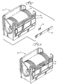
- Molded carrier 12 is provided with a recessed area 14, which is sized to receive bar code tag 16 in one of the planar side walls thereof near the lip 15 at the top open disk-receiving end of the carrier.
- the cover 18 is formed of the same material as the body of the carrier, which is generally a perfluorinated synthetic resin such as TEFLON. Encapsulation by hermetic heat sealing protects the bar code tag from attack by the various chemicals used in the processing of disks.
- Figure 4 illustrates a process carrier with an encapsulated bar code tag, according to the present invention, as shown in the embodiment of Figure 1.
- any method of encapsulation which protects the bar code tag from chemical attack while allowing it to remain visible to a bar code reader unit may suitably be used.
- the bar code tag may alternatively be mounted on any flat surface on the wafer carrier without the costly tooling required to add a recess to accept the bar code tag. Locating the bar code on any flat surface of the wafer carrier permits the choice of location for the bar code which is most advantageous for a particular scanning set-up with minimal interference with other existing procedures and equipment in individual processing operations.
- the bar code tag 54 may be attached by encapsulation on any flat surface of the carrier 50 without the need of providing a recess to receive the tag 54.
- the bar code cover 52 for attaching the tag 54 by encapsulation to the carrier's 50 flat surface may be provided with biased retention tabs 56 for positioning the tag 54 in place during the heat-sealing operation.
- the bar code cover 52 may be made of the same material as bar code cover 18, which is generally the same material as is used for carrier 50 or 12.
- Carrier 50 is generally the same type as carrier 12.
- Bar code tag substrates of anodized aluminum, stainless steel, polymide synthetic resin such as KAPTON perfluorinated synthetic resins such as TEFLON, polyester synthetic resin and ceramic demonstrated acceptable limits of resistance to harsh chemical environments under representative use conditions.
- TEDLAR polyfluorocarbon film
- the bar code indicia is photographically applied to the bar code substrate to ensure accurate readability. Testing conditions have indicated that laser bar code scanners can accurately read the present bar code tags through an optically transparent cover of hermetically heat sealed TEFLON PFA of up to a thickness of approximately .090 inches.
- the bar code tag 16 or 54 consists of a number of spaced apart parallel lines of varying widths. Usually dark lines on a light reflecting background are used but light reflective lines on a dark background also can be used. Data is coded in the width and spacing of the line so that when an optical probe is scanned across the code in a direction normal to the lines, a light beam in the probe is modulated in a manner which is unique to the particular bar code. The scanning can be affected either manually or automatically.
- the modulated light beam is directed to and detected by an electro-optical detector, such as a photodiode or phototransistor. From there the resulting signal is processed and stored in an electronic computer.
- the computer is programmed to provide inventorying, identifying and processing information associated with the carriers.
- the electro-optical probe detectors, or bar code readers 23, which are used to scan the bar codes contain at least two essential components. These are an illuminator and an optical receiver.
- the illuminator is usually a non-collimated light source, such as an incandescent lamp or light emitting diode, or more recently a non-coherent collimated laser light source.
- the illuminator is coupled to a lens which directs the light beam to the surface of the bar code from which the light beam is reflected back and collected by the optical receiver.
- the optical receiver utilizes a second lens to focus the light beam on an electro-optical detector.
- the light source and the light detector may be located adjacent the respective lenses or they may be located remotely and connected to the lenses through electronic components or optical fibers. From the electro-optical detector, the resulting signal is processed and stored by an electronic computer 38.
- bar code scanners based on laser or non-coherent light sources are considered preferable because they allow for rapid reliable non-contact scanning of the encapsulated bar code.
- Bar code readers employing a laser tube as a light source are commonly referred to as laser scanners and have a sufficient depth of field to read bar codes at a distance.
- laser scanners which are commonly known in the art, generally operate by directing a laser beam at a rotating drum or multi-faced mirror or hologram to scan the beam across the bar code. The reflective scattered light is then incident on a photo cell which generates a corresponding voltage so that a voltage pattern with respect to the distance along the length of the bar code is developed.
- the reflectivity-length relationship can be converted to a voltage-time relationship, which is then used to decode the information contained in the encapsulated coded bar code.
- the utilization of laser bar code scanning technology in the present invention enables reading the bar codes at a distance from the disk carriers as they move past a stationary or hand held reader such as on a conveyor or in a continuous processing operation.
- a stationary or hand held reader such as on a conveyor or in a continuous processing operation.
- both stationary and hand held bar code readers or scanners based on laser light sources are presently available. See for example United States Patent No. 4,560,862, Patent No. 4,500,776, Patent No. 4,460,120, Patent No. 4,450,350, Patent No. 4,431,912, Patent No.
- the computer to which the identifying bar code indicia is transmitted may be connected as well to a variety of such desirable peripheral devices as a printer, a keyboard, a communications port, audiovisual enunciators, data display, and similar peripheral devices to constitute an intelligent data acquisition terminal for the information associated with the carriers and disks.
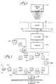
- the system block diagram in Figure 2 is provided to better illustrate the operation of the bar code tag in association with the various bar code readers or scanners.
- a single carrier 12 or 50 with attached bar code 16 or 54 is shown, but it will be readily understood that a plurality of identical or non-identical carriers will generally be used for transporting and storing numerous disk batches undergoing processing in a particular manufacturing facility or between facilities.
- a bar code reader or scanner 23 directs a light beam to the surface of the bar code tag 16 or 54.
- the identification of a bar code, and its associated carrier, by a scanner 23 can take place at distances from virtual contact up to several feet.
- the carrier 12 or 50 must be oriented so that the bar code 16 or 54 is optically visible to the scanner.
- a plurality of bar code indicia readers 23 would normally be used in a manufacturing facility, each reader being stationed at a location adjacent to the place where a particular manufacturing operation takes place.
- the bar code reader outputs are all connected to a converter or digitizer 30 which converts signals from the reader or scanner 23.
- the bar code readers have output signals which are converted from analog to digital form in the digitizer 30 or the computer 38 and decoded into a digital number uniquely identifying each of the bar code tags 16 or 54 and its associated carrier and semiconductor wafer or memory disk batch.
- the unique identification number associated with a bar code tag 16 or 54 and the output signals from a particular bar code reader that detected it allows a master computer to determine at any point and time which of the carriers is at a location of interest within the processing facility.
- FIG. 3 A typical facility application is illustrated in Figure 3 where multiple remote bar code readers designated 23 are each stationed throughout the processing facility at appropriate locations designated as stations I through VIII.
- One or more bar code readers 23 may be positioned adjacent a particular station to monitor carriers as they are received or dispatched from the station or reach an intermediate location at the particular station.
- the outputs of the bar code readers 23A through H are connected to a transmission line 28 which links them via converter 30 with a computer 38 which can be positioned at any convenient location inside or outside of the facility.
- carrier 12 or 50 bearing unique bar code tag 16 moves from station to station within the facility, the presence of the carrier at various stations can be verified and logged by computer 38 from individual readers 23A through 23H.
Landscapes
- Physics & Mathematics (AREA)
- General Physics & Mathematics (AREA)
- Engineering & Computer Science (AREA)
- Theoretical Computer Science (AREA)
- Health & Medical Sciences (AREA)
- Electromagnetism (AREA)
- General Health & Medical Sciences (AREA)
- Toxicology (AREA)
- Artificial Intelligence (AREA)
- Computer Vision & Pattern Recognition (AREA)
- Container, Conveyance, Adherence, Positioning, Of Wafer (AREA)
- Indexing, Searching, Synchronizing, And The Amount Of Synchronization Travel Of Record Carriers (AREA)
Abstract
Description
- This invention relates to a system for identification, tracking and monitoring of the progress of process carriers containing batches of semiconductor wafers or memory disks through a variety of different processing operations at various locations within a plant facility and between different plant facilities using a bar code remote recognition system.
- The semiconductor manufacturing industry requires that process carriers containing semiconductor wafers be moved through a manufacturing plant to a number of different locations where the semiconductor wafers are subjected to a variety of processing operations. Such operations include etching, cleaning, processing using photolithography operations, and subjecting to various other manufacturing, testing and processing operations. The manufacturing of memory disks similarly involves processing through a sequence of manufacturing operations within a manufacturing facility and between different facilities. In this industry, the wafers or memory disks are commonly handled in batches contained within carriers which are specifically designed to support the wafers or memory disks in the proper position for the manufacturing and processing machinery to either handle the disks or wafers while they remain in the carriers or alternatively remove them for a processing operation and then return them to the carrier. A batch, as defined and used hereinafter, means one or more (up to the capacity of the carrier) of the semiconductor wafers or memory disks.
- As a process carrier containing a batch of wafers or memory disks moves throughout the manufacturing plant, it is desirable to track its progress through the manufacturing and processing operations. This has conventionally been done on a manual basis, either by generating paper records to track the progress of process carriers containing particular batches through these various operations or by some semi-automated system such as manual keyboard entry. A method and apparatus for monitoring the location of process carriers containing wafer disks has been disclosed in related United States Patent US-A-4 827 110, published may 2, 1987, which involves the use of RF interrogation of coded surface acoustic wave transponder structures associated with the carriers for wafers or memory disks. However, it is desirable to provide a method for monitoring the location of disks and the carriers containing them which is reliable, involves low capital investment, functions cooperatively with monitoring and tracking systems utilized in other fabrication areas within the industry, allows for rapid, reliable, non-contact monitoring and is impervious to attack by the various chemicals used in the processing of wafer disks. The present invention thus provides a location monitoring system which meets these requirements.
- Methods of identifying, tracking and inventorying using coded bar code indicia have been in existence for about the past 15 years. Bar code indicia conventionally consist of a number of spaced apart parallel lines of varying widths. Data is coded in the width and spacing of the lines, so that when an optical probe is scanned across the code in a direction normal to the lines, a light beam in the probe is modulated in a manner which is unique to the particular code. The modulated light beam is directed and detected by an electro-optical detector and thereafter the resulting signal is processed and stored in an electronic computer.
- Despite the length of time that bar code identification has been available, the application of bar code identifying, tracking and inventorying techniques to monitoring the location and progress of process carriers containing semiconductor wafers or memory disks through processing and manufacturing operations has not heretofore occurred. The application of bar coded systems to wafer or disk process carriers has not been implemented because of the harsh chemical and temperature processing environments to which these carriers are subjected under normal use conditions, which conditions would be destructive to most currently available bar code tags. Most currently available bar code tags are adhered to the substrate surface by adhesives. These tags and/or their adhesives would be readily deteriorated by the action of harsh chemicals. Also, although newer adhesives have reasonably good adherence to the surface of the process carriers, typically formed of TEFLON, even these newer adhesives are soon deteriorated by the chemicals used in processing. An acceptable bar code tag for process carriers must not be affected by chemical attack during the useful life of the carrier and must not contaminate or contribute to contamination of the chemical process baths.
- The EP-A-0 151 533 discloses to use bar codes in connection with metal beer kegs as means of identification. The bar code strip is adhered to the back surface of a transparent plate which is surrounded by an overlapping peripheral metal frame welded to the beer keg. The plate is made of a material which cannot be shattered by blows from a hammer. It is also caustic resistant, scratch proof and acid proof.
- This invention presents an encapsulation system for attaching a bar code tag to a process carrier, so that the tag is protected from the harsh chemical environment to which the carrier is to be subjected, while at the same time allowing the bar code indicia to be readily and accurately readable by conventionally available bar code scanners, preferably laser scanners. The invention is as specified in claim 1.
- The present invention provides a method for monitoring the location and progress of a plurality of process carriers containing batches of semiconductor wafers or memory disks through a multiplicity of processing operations. The method includes inserting each of the batches of wafers or memory disks into a carrier constructed and arranged for supporting the wafers or disks in parallel, axially arranged spaced arrays. The carrier is adapted to permit the carrying out of processing operations at various locations within the plant without removal of the batch of semiconductor wafers and memory disks from the carrier. Each carrier is provided with a coded bar code indicia tag, attached to the carrier in such a way as to effect optimum protection of the tag from the harsh chemical environments to which the process carrier is to be subjected. The bar code tag is coded to uniquely identify the carrier and the associated batch of wafers or disks contained therein. The proximity of each carrier to various locations within the processing facility is detected by a multiplicity of bar code indicia reader units, each of which is positioned at one of various locations and is constructed and arranged for determining the unique identification of any carrier within its detection range by means of the uniquely coded bar code indicia tag attached to a particular carrier. The progress of process carriers containing batches through processing operations is monitored by storing and updating carrier identification information from the bar code indicia reader units.
-
- Figure 1, is a partially exploded pictorial drawing of a typical carrier;
- Figure 2, is a block diagram of the bar code indicia monitoring system;
- Figure 3, is a schematic layout of a typical plant facility;
- Figure 4, is a pictorial of a typical carrier according to Fig. 1 with a coded bar code indicia tag encapsulated according to the present invention;
- Figure 5, is a profile of a cover for retaining a bar code tag for encapsulation onto a surface of carrier according to an alternative embodiment of this invention; and
- Figure 6 is a pictorial of a process carrier with an encapsulated bar code on its surface using the cover of Figure 5.
- In Figure 1, a typical wafer or disk carrier suitable for transporting and supporting a plurality of semiconductor wafers or
memory disks 17 in a parallel axially arranged and spaced array is identified generally withreference character 12. The term "disk" hereinafter is used to designate either a semiconductor wafer or a computer memory disk, since the technology described here may suitably be used for either type of product as well as any other generally similar product having a thickness which is substantially less than the width. Such carriers are currently commercially available from Fluoroware, Inc., 102 Jonathan Boulevard North, Chaska, Minnesota 55318 and are in wide spread use generally in the semiconductor manufacturing industry. Conventionally, such carriers have been tracked through manufacturing operations by associating paper records with particular carriers and the batches of wafers or disks therein or by some semi-automated system such as manual keyboard entry. -
Molded carrier 12 is provided with arecessed area 14, which is sized to receivebar code tag 16 in one of the planar side walls thereof near thelip 15 at the top open disk-receiving end of the carrier. An opticallytransparent cover 18, sized to fit and close the recessed area after thebar code tag 16 has been set in place, is hermetically heat sealed tocarrier 12. Preferably, thecover 18 is formed of the same material as the body of the carrier, which is generally a perfluorinated synthetic resin such as TEFLON. Encapsulation by hermetic heat sealing protects the bar code tag from attack by the various chemicals used in the processing of disks. Placing the bar code tag in this location, immediately below the projectinglip 15 at the top open disk-receiving end of the carrier permits thecarrier 12 to be used without interference in the normal manner throughout the manufacturing and transporting processes. Figure 4 illustrates a process carrier with an encapsulated bar code tag, according to the present invention, as shown in the embodiment of Figure 1. - Alternatively, any method of encapsulation which protects the bar code tag from chemical attack while allowing it to remain visible to a bar code reader unit, may suitably be used. In addition, the bar code tag may alternatively be mounted on any flat surface on the wafer carrier without the costly tooling required to add a recess to accept the bar code tag. Locating the bar code on any flat surface of the wafer carrier permits the choice of location for the bar code which is most advantageous for a particular scanning set-up with minimal interference with other existing procedures and equipment in individual processing operations.
- For example, as shown in Figure 6, the
bar code tag 54 may be attached by encapsulation on any flat surface of the carrier 50 without the need of providing a recess to receive thetag 54. The bar code cover 52 for attaching thetag 54 by encapsulation to the carrier's 50 flat surface, may be provided withbiased retention tabs 56 for positioning thetag 54 in place during the heat-sealing operation. Thebar code cover 52 may be made of the same material asbar code cover 18, which is generally the same material as is used forcarrier 50 or 12. Carrier 50 is generally the same type ascarrier 12. - Certain specific materials have been determined according to the present invention to be particularly suitable for the bar code tags. Bar code tag substrates of anodized aluminum, stainless steel, polymide synthetic resin such as KAPTON perfluorinated synthetic resins such as TEFLON, polyester synthetic resin and ceramic demonstrated acceptable limits of resistance to harsh chemical environments under representative use conditions. Testing of encapsulated bar code tags according to the present invention was carried out using the following typical semiconductor processing chemicals:
Semiconductor Process Chemicals Used in Testing Chemical Formula Ratio Hydrofluoric Acid HF:H2O 1:1 Dilute Hydrofluoric Acid H2O:HF (50%) 15:1 Buffered Hydrofluoric Acid HF:NH4F:H2O 49:40:11 Nitric Acid HNO3:H2O 7:3 Aluminum Etch H3PO4:HNO3COOH:H2O 85:5:5:5 Aqua Regia HNO3:HCl 1:3 Piranha H2SO4:H2O2 5:1 RCA Clean H2O:NH4OH:H2O2 9:2:1 Sodium Hydroxide NaOH:H2O 1.1 Hydrochloric Acid HCl:H2O 37:63 Water H2O Hydrogen Peroxide H2O2:H2O 3:7 - Preferably, the bar code indicia is photographically applied to the bar code substrate to ensure accurate readability. Testing conditions have indicated that laser bar code scanners can accurately read the present bar code tags through an optically transparent cover of hermetically heat sealed TEFLON PFA of up to a thickness of approximately .090 inches.
- The
bar code tag - Generally, the electro-optical probe detectors, or
bar code readers 23, which are used to scan the bar codes contain at least two essential components. These are an illuminator and an optical receiver. The illuminator is usually a non-collimated light source, such as an incandescent lamp or light emitting diode, or more recently a non-coherent collimated laser light source. The illuminator is coupled to a lens which directs the light beam to the surface of the bar code from which the light beam is reflected back and collected by the optical receiver. The optical receiver utilizes a second lens to focus the light beam on an electro-optical detector. The light source and the light detector may be located adjacent the respective lenses or they may be located remotely and connected to the lenses through electronic components or optical fibers. From the electro-optical detector, the resulting signal is processed and stored by anelectronic computer 38. - For purposes of the present invention, bar code scanners based on laser or non-coherent light sources are considered preferable because they allow for rapid reliable non-contact scanning of the encapsulated bar code. Bar code readers employing a laser tube as a light source are commonly referred to as laser scanners and have a sufficient depth of field to read bar codes at a distance. Such laser scanners, which are commonly known in the art, generally operate by directing a laser beam at a rotating drum or multi-faced mirror or hologram to scan the beam across the bar code. The reflective scattered light is then incident on a photo cell which generates a corresponding voltage so that a voltage pattern with respect to the distance along the length of the bar code is developed. Because the rotational speed of the drum or mirrors or hologram is known, the reflectivity-length relationship can be converted to a voltage-time relationship, which is then used to decode the information contained in the encapsulated coded bar code. The utilization of laser bar code scanning technology in the present invention enables reading the bar codes at a distance from the disk carriers as they move past a stationary or hand held reader such as on a conveyor or in a continuous processing operation. As has been indicated, both stationary and hand held bar code readers or scanners based on laser light sources are presently available. See for example United States Patent No. 4,560,862, Patent No. 4,500,776, Patent No. 4,460,120, Patent No. 4,450,350, Patent No. 4,431,912, Patent No. 4,387,297, and Patent No. 4,333,006. In addition, portable laser scanners are available to permit reading of coded bar code indicia passed underneath or along side of the scanning head. See for example United States Patent No. 4,369,361. This allows the bar code symbols on the carrier walls to be oriented facing the operator during their passage past the scanner to facilitate sighting and registration of the bar code symbol with the laser light beam generated by the scanner head.
- The computer to which the identifying bar code indicia is transmitted, may be connected as well to a variety of such desirable peripheral devices as a printer, a keyboard, a communications port, audiovisual enunciators, data display, and similar peripheral devices to constitute an intelligent data acquisition terminal for the information associated with the carriers and disks.
- The system block diagram in Figure 2 is provided to better illustrate the operation of the bar code tag in association with the various bar code readers or scanners. For this illustration, a
single carrier 12 or 50 with attachedbar code scanner 23 directs a light beam to the surface of thebar code tag scanner 23 can take place at distances from virtual contact up to several feet. Thecarrier 12 or 50 must be oriented so that thebar code - A plurality of bar
code indicia readers 23 would normally be used in a manufacturing facility, each reader being stationed at a location adjacent to the place where a particular manufacturing operation takes place. The bar code reader outputs are all connected to a converter ordigitizer 30 which converts signals from the reader orscanner 23. In the preferred embodiment shown, the bar code readers have output signals which are converted from analog to digital form in thedigitizer 30 or thecomputer 38 and decoded into a digital number uniquely identifying each of the bar code tags 16 or 54 and its associated carrier and semiconductor wafer or memory disk batch. The unique identification number associated with abar code tag - A typical facility application is illustrated in Figure 3 where multiple remote bar code readers designated 23 are each stationed throughout the processing facility at appropriate locations designated as stations I through VIII. One or more
bar code readers 23 may be positioned adjacent a particular station to monitor carriers as they are received or dispatched from the station or reach an intermediate location at the particular station. The outputs of the bar code readers 23A through H are connected to atransmission line 28 which links them viaconverter 30 with acomputer 38 which can be positioned at any convenient location inside or outside of the facility. Ascarrier 12 or 50 bearing uniquebar code tag 16 moves from station to station within the facility, the presence of the carrier at various stations can be verified and logged bycomputer 38 from individual readers 23A through 23H. - It will be realized by those skilled in the art that various modifications and additions to the method and system disclosed herein may be made without departing from the essential features of novelty of the invention which are intended to be defined and secured by the appended claims.
Claims (4)
- A system for tracking batches of semiconductor wafer or memory disks through a plurality of operations in a chemical environment comprising:a plurality of carriers (12, 50) which are formed of perfluorinated synthetic resins, each of which is adpated for carrying a batch of at least one disk (17) and each of which carrier (12, 50) has encapsulated on the outside surface of the vertical wall an optically visible bar code tag (16, 54) including a unique array of spaced apart parallel lines of varying widths contained data coded in the width and spacing of the lines uniquely identifying a single carrier (12, 50), the bar code tag (16, 54) being formed of anodized aluminum, polymide synthetic resin, stainless steel, perfluorinated synthetic resin, ceramic or polyester synthetic resin and the bar code tag (16, 50) being attached to a surface of the carrier by hermetic heat sealing under an optically transparent cover (18, 52) also of perfluorinated synthetic resin;at leat one remote recognition bar code reader (23) constructed and arranged for directing a modulated light beam across the bar code in a direction normal to the lines and receiving back a reflective light beam uniquely characteristic of that bar code and control means (30, 38) for receiving the output from the bar code readers (23) and providing a control signal indicative of which carrier (12, 50) is within the range of which bar code reader.
- The system of claim 1, wherein each of the bar code reader units (23) directs a modulated light beam from a laser light source to the bar code tag (16, 52) within its detection range.
- The system of claim 1 or 2, wherein the bar code tag (16) is mounted on the carrier by inserting the bar code tag in a recess (14) in a surface of the carrier, the recess (14) being constructed and arranged for supporting the bar code tag (16).
- The system of claim 1 or 2, wherein the rear side of the cover (52) has retaining tabs (56) for retaining the bar code tag (54) therebetween during heat sealing of the cover (52) to the carrier.
Applications Claiming Priority (3)
| Application Number | Priority Date | Filing Date | Title |
|---|---|---|---|
| US196132 | 1988-05-18 | ||
| US07/196,132 US4833306A (en) | 1988-05-18 | 1988-05-18 | Bar code remote recognition system for process carriers of wafer disks |
| PCT/US1989/000652 WO1989011702A1 (en) | 1988-05-18 | 1989-02-17 | Bar code remote recognition system for process carriers of wafer disks |
Publications (3)
| Publication Number | Publication Date |
|---|---|
| EP0382797A1 EP0382797A1 (en) | 1990-08-22 |
| EP0382797A4 EP0382797A4 (en) | 1992-05-27 |
| EP0382797B1 true EP0382797B1 (en) | 1996-07-03 |
Family
ID=22724212
Family Applications (1)
| Application Number | Title | Priority Date | Filing Date |
|---|---|---|---|
| EP89902909A Expired - Lifetime EP0382797B1 (en) | 1988-05-18 | 1989-02-17 | Bar code remote recognition system for process carriers of wafer disks |
Country Status (8)
| Country | Link |
|---|---|
| US (1) | US4833306A (en) |
| EP (1) | EP0382797B1 (en) |
| JP (1) | JPH03500700A (en) |
| KR (1) | KR930012138B1 (en) |
| AT (1) | ATE140090T1 (en) |
| CA (1) | CA1314986C (en) |
| DE (1) | DE68926782T2 (en) |
| WO (1) | WO1989011702A1 (en) |
Families Citing this family (46)
| Publication number | Priority date | Publication date | Assignee | Title |
|---|---|---|---|---|
| US5536128A (en) * | 1988-10-21 | 1996-07-16 | Hitachi, Ltd. | Method and apparatus for carrying a variety of products |
| CA2011296A1 (en) | 1989-05-15 | 1990-11-15 | Douglas C. Bossen | Presence/absence bar code |
| US5055832A (en) * | 1989-06-09 | 1991-10-08 | Dayco Products Canada Inc. | Display element with notched disk |
| IT1235835B (en) * | 1989-08-08 | 1992-11-03 | Sgs Thomson Microelectronics | AUTOMATIC HANDLING OF DIFFERENT CONTAINERS WITH STANDARDIZED COLLECTION AND CODING POINTS |
| GB9007132D0 (en) * | 1990-03-30 | 1990-05-30 | Gen Foods Kraft Ltd | Packages containing comestibles |
| US5570293A (en) * | 1990-11-29 | 1996-10-29 | Tokyo Seimitsu Co., Ltd. | Method and device for manufacturing a semiconductor chip |
| US5399531A (en) * | 1990-12-17 | 1995-03-21 | United Micrpelectronics Corporation | Single semiconductor wafer transfer method and plural processing station manufacturing system |
| US5559398A (en) * | 1991-11-28 | 1996-09-24 | Hitachi, Ltd. | Cathode ray tube and method of making the same |
| CA2097204A1 (en) * | 1992-06-15 | 1993-12-16 | Paul William Spencer | Maintenance monitoring system for detachable ski lift carrier vehicles |
| US5300762A (en) * | 1992-06-25 | 1994-04-05 | Siemens Power Corporation | Non-contact shoe for bar code wands |
| JP2647795B2 (en) * | 1992-12-03 | 1997-08-27 | 日本バルカー工業株式会社 | Heat fusion method of mark plate |
| DE4309092C2 (en) * | 1993-03-22 | 1998-11-12 | Joachim Dr Scheerer | Method and device for handling and transporting wafers in ultra-clean rooms |
| US5521709A (en) * | 1993-05-05 | 1996-05-28 | International Business Machines Corporation | Continuous barcode marking system |
| JPH0722490A (en) * | 1993-06-30 | 1995-01-24 | Mitsubishi Electric Corp | Automatic lot forming apparatus and method |
| US5472086A (en) * | 1994-03-11 | 1995-12-05 | Holliday; James E. | Enclosed sealable purgible semiconductor wafer holder |
| US6164530A (en) * | 1994-04-08 | 2000-12-26 | Fluoroware, Inc. | Disk carrier with transponder |
| US5476176A (en) * | 1994-05-23 | 1995-12-19 | Empak, Inc. | Reinforced semiconductor wafer holder |
| US5560775A (en) * | 1994-05-23 | 1996-10-01 | Advanced Micro Devices, Inc. | Quartz marking system |
| US5537431A (en) * | 1994-06-15 | 1996-07-16 | International Business Machines Corporation | Method and apparatus for bar code reading and decoding |
| USD368802S (en) | 1994-10-13 | 1996-04-16 | Gallagher Gary M | 150 mm wafer cassette for use on 200 mm semi standard wafer handling equipment |
| US5581071A (en) * | 1994-12-06 | 1996-12-03 | International Business Machines Corporation | Barcode scanner with adjustable light source intensity |
| US5770842A (en) * | 1995-06-08 | 1998-06-23 | Dressen; Larry G. | Location monitoring of wafer batches |
| KR100207446B1 (en) * | 1995-07-08 | 1999-07-15 | 윤종용 | Cassette manufacture & cognition method for semiconductor administration |
| US5742238A (en) * | 1995-09-01 | 1998-04-21 | Emtrak, Inc. | System for communication between a central controller and items in a factory using infrared light |
| KR0182926B1 (en) * | 1996-06-29 | 1999-05-15 | 김광호 | Quality Management System and Quality Control Method Using Bar-Code System |
| DE19640425A1 (en) * | 1996-09-30 | 1998-04-02 | Siemens Ag | Process for wafer identification in chip production and device for carrying out the process |
| US5942739A (en) * | 1997-01-22 | 1999-08-24 | Advanced Micro Devices, Inc. | Process timer monitor |
| US6138058A (en) * | 1998-01-06 | 2000-10-24 | Jenoptik Infab, Inc. | Method for electronically tracking containers to avoid misprocessing of contents |
| US6136614A (en) * | 1998-03-04 | 2000-10-24 | Agilent Technologies | Apparatus and method for manufacturing integrated circuit devices |
| US7229017B2 (en) * | 1999-11-23 | 2007-06-12 | Xerox Corporation | Laser locating and tracking system for externally activated tags |
| US6669253B2 (en) * | 2000-12-18 | 2003-12-30 | David W. Benzing | Wafer boat and boat holder |
| US6451421B1 (en) * | 2001-03-19 | 2002-09-17 | Infosight Corporation | Laser markable micro-pore aluminum tags and method of their fabrication |
| US6618640B1 (en) * | 2001-04-11 | 2003-09-09 | Advanced Micro Devices, Inc. | Method and apparatus for using integrated remote identifier |
| WO2002096788A1 (en) * | 2001-05-31 | 2002-12-05 | Inventio Ag | Device for determining the position of a rail-guided elevator car with a code support |
| EP1458557A1 (en) * | 2001-11-27 | 2004-09-22 | Entegris, Inc. | Informational polymer film insert molding |
| US6641039B2 (en) * | 2002-03-21 | 2003-11-04 | Alcon, Inc. | Surgical procedure identification system |
| ATE359035T1 (en) * | 2002-03-21 | 2007-05-15 | Alcon Inc | SURGICAL SYSTEM |
| US7175026B2 (en) | 2002-05-03 | 2007-02-13 | Maxtor Corporation | Memory disk shipping container with improved contaminant control |
| US6738294B2 (en) * | 2002-09-30 | 2004-05-18 | Agere Systems Inc. | Electronic fingerprinting of semiconductor integrated circuits |
| CA2803828C (en) * | 2005-03-31 | 2015-11-24 | Alcon, Inc. | Footswitch operable to control a surgical system |
| US8011905B2 (en) | 2005-11-17 | 2011-09-06 | Novartis Ag | Surgical cassette |
| US7392144B2 (en) * | 2006-10-10 | 2008-06-24 | Alcon, Inc. | Method for data compression and encoding |
| US8465473B2 (en) * | 2007-03-28 | 2013-06-18 | Novartis Ag | Surgical footswitch with movable shroud |
| JP2011522609A (en) * | 2008-06-05 | 2011-08-04 | アルコン リサーチ, リミテッド | Wireless network and wireless communication method for an ophthalmic surgical console |
| DE102018101439B4 (en) * | 2018-01-23 | 2020-01-09 | RF360 Europe GmbH | Substrate carrier for a reflow oven and use of a substrate carrier |
| US20240189958A1 (en) * | 2022-12-07 | 2024-06-13 | Illinois Tool Works Inc. | Systems and methods to detect rotation of a vibratory polisher |
Family Cites Families (7)
| Publication number | Priority date | Publication date | Assignee | Title |
|---|---|---|---|---|
| US4263503A (en) * | 1979-09-25 | 1981-04-21 | Bianco James S | Bar code label protection device |
| AU582355B2 (en) * | 1984-01-30 | 1989-03-23 | John Gordon Bailey | Identification means |
| US4625101A (en) * | 1984-02-27 | 1986-11-25 | The Goodyear Tire & Rubber Company | Bar code configuration and method of molding |
| US4809342A (en) * | 1984-11-27 | 1989-02-28 | Kappner Helmut A | Process and arrangements for the indentification marking and recognition of objects |
| JPS61257820A (en) * | 1985-05-09 | 1986-11-15 | Fuji Facom Corp | Control system for conveyor line |
| EP0220380A2 (en) * | 1985-07-05 | 1987-05-06 | Irving N. Arnold Associates, Ltd. | Data storage and retrieval apparatus for controlling systems |
| JPS63108482A (en) * | 1986-10-27 | 1988-05-13 | Matsushita Electric Works Ltd | Method for displaying source marking |
-
1988
- 1988-05-18 US US07/196,132 patent/US4833306A/en not_active Expired - Lifetime
-
1989
- 1989-02-17 JP JP1502701A patent/JPH03500700A/en active Pending
- 1989-02-17 DE DE68926782T patent/DE68926782T2/en not_active Expired - Fee Related
- 1989-02-17 AT AT89902909T patent/ATE140090T1/en not_active IP Right Cessation
- 1989-02-17 EP EP89902909A patent/EP0382797B1/en not_active Expired - Lifetime
- 1989-02-17 WO PCT/US1989/000652 patent/WO1989011702A1/en not_active Ceased
- 1989-02-17 KR KR1019900700092A patent/KR930012138B1/en not_active Expired - Fee Related
- 1989-02-24 CA CA000592034A patent/CA1314986C/en not_active Expired - Fee Related
Also Published As
| Publication number | Publication date |
|---|---|
| DE68926782T2 (en) | 1996-10-31 |
| KR930012138B1 (en) | 1993-12-24 |
| EP0382797A1 (en) | 1990-08-22 |
| EP0382797A4 (en) | 1992-05-27 |
| CA1314986C (en) | 1993-03-23 |
| ATE140090T1 (en) | 1996-07-15 |
| DE68926782D1 (en) | 1996-08-08 |
| KR900702475A (en) | 1990-12-07 |
| US4833306A (en) | 1989-05-23 |
| JPH03500700A (en) | 1991-02-14 |
| WO1989011702A1 (en) | 1989-11-30 |
Similar Documents
| Publication | Publication Date | Title |
|---|---|---|
| US4833306A (en) | Bar code remote recognition system for process carriers of wafer disks | |
| US4827110A (en) | Method and apparatus for monitoring the location of wafer disks | |
| EP0336769B1 (en) | Hexagonal information encoding article, process and system | |
| EP0573129B1 (en) | Polygonal information encoding article | |
| GB2259631A (en) | A device for identifying a person or object | |
| US4636634A (en) | Apparatus with intelligent bins indicating the presence and identity of stored coded articles | |
| US6974782B2 (en) | Reticle tracking and cleaning | |
| JP2651357B2 (en) | Disk carrier and disk monitoring system and method using disk carrier | |
| EP0036781A1 (en) | Method of reading bar code symbols on an object | |
| US6138058A (en) | Method for electronically tracking containers to avoid misprocessing of contents | |
| FR2743194A1 (en) | POINT CARD IDENTIFICATION FOR COMPUTER-AIDED MANUFACTURING | |
| US6890759B2 (en) | System and method for universal identification of biological samples | |
| US6529154B1 (en) | Method and apparatus for reading two dimensional identification symbols using radar techniques | |
| EP0085696B1 (en) | A method and apparatus for sorting coded tagged articles | |
| EP0270634B1 (en) | System for scanning coded indicia | |
| Plain‐Jones | Data matrix identification | |
| CA2020540C (en) | Bar code reader | |
| CN218156462U (en) | Cloud control platform | |
| JPH03252891A (en) | Reader | |
| JPH03271988A (en) | Reader | |
| JPH11224315A (en) | Recognition device | |
| JPH03252889A (en) | Reader | |
| JPH06176184A (en) | Bar code reading method and production/test line | |
| JP2003058818A (en) | Bar code label and bar code detection system using the label | |
| JPH0384687A (en) | Reader |
Legal Events
| Date | Code | Title | Description |
|---|---|---|---|
| PUAI | Public reference made under article 153(3) epc to a published international application that has entered the european phase |
Free format text: ORIGINAL CODE: 0009012 |
|
| 17P | Request for examination filed |
Effective date: 19900510 |
|
| AK | Designated contracting states |
Kind code of ref document: A1 Designated state(s): AT BE CH DE FR GB IT LI LU NL SE |
|
| A4 | Supplementary search report drawn up and despatched |
Effective date: 19920406 |
|
| AK | Designated contracting states |
Kind code of ref document: A4 Designated state(s): AT BE CH DE FR GB IT LI LU NL SE |
|
| 17Q | First examination report despatched |
Effective date: 19930202 |
|
| GRAH | Despatch of communication of intention to grant a patent |
Free format text: ORIGINAL CODE: EPIDOS IGRA |
|
| GRAH | Despatch of communication of intention to grant a patent |
Free format text: ORIGINAL CODE: EPIDOS IGRA |
|
| GRAA | (expected) grant |
Free format text: ORIGINAL CODE: 0009210 |
|
| AK | Designated contracting states |
Kind code of ref document: B1 Designated state(s): AT BE CH DE FR GB IT LI LU NL SE |
|
| REF | Corresponds to: |
Ref document number: 140090 Country of ref document: AT Date of ref document: 19960715 Kind code of ref document: T |
|
| REG | Reference to a national code |
Ref country code: CH Ref legal event code: NV Representative=s name: ISLER & PEDRAZZINI AG |
|
| REF | Corresponds to: |
Ref document number: 68926782 Country of ref document: DE Date of ref document: 19960808 |
|
| ITF | It: translation for a ep patent filed | ||
| ET | Fr: translation filed |
Free format text: CORRECTIONS |
|
| PG25 | Lapsed in a contracting state [announced via postgrant information from national office to epo] |
Ref country code: AT Free format text: LAPSE BECAUSE OF NON-PAYMENT OF DUE FEES Effective date: 19970217 |
|
| PG25 | Lapsed in a contracting state [announced via postgrant information from national office to epo] |
Ref country code: SE Effective date: 19970218 |
|
| PG25 | Lapsed in a contracting state [announced via postgrant information from national office to epo] |
Ref country code: LU Free format text: LAPSE BECAUSE OF NON-PAYMENT OF DUE FEES Effective date: 19970228 Ref country code: LI Effective date: 19970228 Ref country code: CH Effective date: 19970228 Ref country code: BE Effective date: 19970228 |
|
| PLBE | No opposition filed within time limit |
Free format text: ORIGINAL CODE: 0009261 |
|
| STAA | Information on the status of an ep patent application or granted ep patent |
Free format text: STATUS: NO OPPOSITION FILED WITHIN TIME LIMIT |
|
| 26N | No opposition filed | ||
| BERE | Be: lapsed |
Owner name: FLUOROWARE INC. Effective date: 19970228 |
|
| PG25 | Lapsed in a contracting state [announced via postgrant information from national office to epo] |
Ref country code: NL Effective date: 19970901 |
|
| REG | Reference to a national code |
Ref country code: CH Ref legal event code: PL |
|
| EUG | Se: european patent has lapsed |
Ref document number: 89902909.4 |
|
| NLV4 | Nl: lapsed or anulled due to non-payment of the annual fee |
Effective date: 19970901 |
|
| PGFP | Annual fee paid to national office [announced via postgrant information from national office to epo] |
Ref country code: GB Payment date: 19990218 Year of fee payment: 11 |
|
| PG25 | Lapsed in a contracting state [announced via postgrant information from national office to epo] |
Ref country code: GB Free format text: LAPSE BECAUSE OF NON-PAYMENT OF DUE FEES Effective date: 20000217 |
|
| GBPC | Gb: european patent ceased through non-payment of renewal fee |
Effective date: 20000217 |
|
| PGFP | Annual fee paid to national office [announced via postgrant information from national office to epo] |
Ref country code: FR Payment date: 20040202 Year of fee payment: 16 |
|
| PGFP | Annual fee paid to national office [announced via postgrant information from national office to epo] |
Ref country code: DE Payment date: 20040227 Year of fee payment: 16 |
|
| PG25 | Lapsed in a contracting state [announced via postgrant information from national office to epo] |
Ref country code: IT Free format text: LAPSE BECAUSE OF NON-PAYMENT OF DUE FEES Effective date: 20050217 |
|
| PG25 | Lapsed in a contracting state [announced via postgrant information from national office to epo] |
Ref country code: DE Free format text: LAPSE BECAUSE OF NON-PAYMENT OF DUE FEES Effective date: 20050901 |
|
| PG25 | Lapsed in a contracting state [announced via postgrant information from national office to epo] |
Ref country code: FR Free format text: LAPSE BECAUSE OF NON-PAYMENT OF DUE FEES Effective date: 20051031 |
|
| REG | Reference to a national code |
Ref country code: FR Ref legal event code: ST Effective date: 20051031 |