EP0382579B1 - An effluent treatment system - Google Patents
An effluent treatment system Download PDFInfo
- Publication number
- EP0382579B1 EP0382579B1 EP19900301468 EP90301468A EP0382579B1 EP 0382579 B1 EP0382579 B1 EP 0382579B1 EP 19900301468 EP19900301468 EP 19900301468 EP 90301468 A EP90301468 A EP 90301468A EP 0382579 B1 EP0382579 B1 EP 0382579B1
- Authority
- EP
- European Patent Office
- Prior art keywords
- effluent
- peat
- medium
- treatment medium
- container
- Prior art date
- Legal status (The legal status is an assumption and is not a legal conclusion. Google has not performed a legal analysis and makes no representation as to the accuracy of the status listed.)
- Expired - Lifetime
Links
- 238000011282 treatment Methods 0.000 title claims abstract description 64
- 239000003415 peat Substances 0.000 claims abstract description 55
- 241000736285 Sphagnum Species 0.000 claims abstract description 11
- 239000008240 homogeneous mixture Substances 0.000 claims abstract description 8
- 239000002657 fibrous material Substances 0.000 claims description 14
- 241000202844 Eriophorum Species 0.000 claims description 10
- 238000011068 loading method Methods 0.000 claims description 9
- 239000000463 material Substances 0.000 claims description 9
- 239000004575 stone Substances 0.000 claims description 8
- 241000196324 Embryophyta Species 0.000 claims description 6
- 230000001939 inductive effect Effects 0.000 claims description 5
- 239000000203 mixture Substances 0.000 claims description 5
- 239000007787 solid Substances 0.000 claims description 5
- 239000000835 fiber Substances 0.000 abstract description 23
- 238000011221 initial treatment Methods 0.000 abstract description 2
- 238000005056 compaction Methods 0.000 description 4
- 238000010276 construction Methods 0.000 description 4
- 230000005484 gravity Effects 0.000 description 4
- 238000005086 pumping Methods 0.000 description 4
- 239000004033 plastic Substances 0.000 description 3
- 229920003023 plastic Polymers 0.000 description 3
- XLYOFNOQVPJJNP-UHFFFAOYSA-N water Substances O XLYOFNOQVPJJNP-UHFFFAOYSA-N 0.000 description 3
- QGZKDVFQNNGYKY-UHFFFAOYSA-N Ammonia Chemical compound N QGZKDVFQNNGYKY-UHFFFAOYSA-N 0.000 description 2
- 241000602285 Sphagnum imbricatum Species 0.000 description 2
- 241000602018 Sphagnum nemoreum Species 0.000 description 2
- 230000000694 effects Effects 0.000 description 2
- 235000007575 Calluna vulgaris Nutrition 0.000 description 1
- 229920000742 Cotton Polymers 0.000 description 1
- 239000004793 Polystyrene Substances 0.000 description 1
- 229910021529 ammonia Inorganic materials 0.000 description 1
- QVGXLLKOCUKJST-UHFFFAOYSA-N atomic oxygen Chemical compound [O] QVGXLLKOCUKJST-UHFFFAOYSA-N 0.000 description 1
- 230000004071 biological effect Effects 0.000 description 1
- 210000003850 cellular structure Anatomy 0.000 description 1
- 238000000354 decomposition reaction Methods 0.000 description 1
- 235000013305 food Nutrition 0.000 description 1
- 239000012634 fragment Substances 0.000 description 1
- 239000003673 groundwater Substances 0.000 description 1
- 238000010348 incorporation Methods 0.000 description 1
- 239000007788 liquid Substances 0.000 description 1
- 230000007774 longterm Effects 0.000 description 1
- 229910052760 oxygen Inorganic materials 0.000 description 1
- 239000001301 oxygen Substances 0.000 description 1
- 229920002223 polystyrene Polymers 0.000 description 1
- 239000011148 porous material Substances 0.000 description 1
- 239000000523 sample Substances 0.000 description 1
- 229920006395 saturated elastomer Polymers 0.000 description 1
- 239000010865 sewage Substances 0.000 description 1
- 239000002352 surface water Substances 0.000 description 1
- 230000003797 telogen phase Effects 0.000 description 1
- 239000002699 waste material Substances 0.000 description 1
Images




Classifications
-
- C—CHEMISTRY; METALLURGY
- C02—TREATMENT OF WATER, WASTE WATER, SEWAGE, OR SLUDGE
- C02F—TREATMENT OF WATER, WASTE WATER, SEWAGE, OR SLUDGE
- C02F3/00—Biological treatment of water, waste water, or sewage
- C02F3/28—Anaerobic digestion processes
- C02F3/2866—Particular arrangements for anaerobic reactors
- C02F3/288—Particular arrangements for anaerobic reactors comprising septic tanks combined with a filter
-
- C—CHEMISTRY; METALLURGY
- C02—TREATMENT OF WATER, WASTE WATER, SEWAGE, OR SLUDGE
- C02F—TREATMENT OF WATER, WASTE WATER, SEWAGE, OR SLUDGE
- C02F3/00—Biological treatment of water, waste water, or sewage
- C02F3/02—Aerobic processes
- C02F3/04—Aerobic processes using trickle filters
-
- C—CHEMISTRY; METALLURGY
- C02—TREATMENT OF WATER, WASTE WATER, SEWAGE, OR SLUDGE
- C02F—TREATMENT OF WATER, WASTE WATER, SEWAGE, OR SLUDGE
- C02F3/00—Biological treatment of water, waste water, or sewage
- C02F3/02—Aerobic processes
- C02F3/10—Packings; Fillings; Grids
-
- Y—GENERAL TAGGING OF NEW TECHNOLOGICAL DEVELOPMENTS; GENERAL TAGGING OF CROSS-SECTIONAL TECHNOLOGIES SPANNING OVER SEVERAL SECTIONS OF THE IPC; TECHNICAL SUBJECTS COVERED BY FORMER USPC CROSS-REFERENCE ART COLLECTIONS [XRACs] AND DIGESTS
- Y02—TECHNOLOGIES OR APPLICATIONS FOR MITIGATION OR ADAPTATION AGAINST CLIMATE CHANGE
- Y02W—CLIMATE CHANGE MITIGATION TECHNOLOGIES RELATED TO WASTEWATER TREATMENT OR WASTE MANAGEMENT
- Y02W10/00—Technologies for wastewater treatment
- Y02W10/10—Biological treatment of water, waste water, or sewage
-
- Y—GENERAL TAGGING OF NEW TECHNOLOGICAL DEVELOPMENTS; GENERAL TAGGING OF CROSS-SECTIONAL TECHNOLOGIES SPANNING OVER SEVERAL SECTIONS OF THE IPC; TECHNICAL SUBJECTS COVERED BY FORMER USPC CROSS-REFERENCE ART COLLECTIONS [XRACs] AND DIGESTS
- Y10—TECHNICAL SUBJECTS COVERED BY FORMER USPC
- Y10S—TECHNICAL SUBJECTS COVERED BY FORMER USPC CROSS-REFERENCE ART COLLECTIONS [XRACs] AND DIGESTS
- Y10S210/00—Liquid purification or separation
- Y10S210/902—Materials removed
- Y10S210/916—Odor, e.g. including control or abatement
Definitions
- the invention relates to an effluent treatment system of the type comprising: a container having an upper inlet for effluent and a lower outlet for treated effluent; and a biological effluent treatment medium in the container.
- peat beds can accommodate only relatively low loadings which, because of the large surface area required, are expensive and impractical to use in many applications.
- FR-A-2337106 describes an effluent treatment of this type.
- the filter medium suggested is peat which may be mixed with natural or artificial spongy waste material.
- the effluent which is treated is first passed through an initial microscreening step. Further, the filter surface is relatively thin and divided into zones to give activity phases and rest phases. There is no residence time in the initial microscreening step so that substantially no biological treatment takes place. Further, the particular filter medium employed presents problems as even if peat mixed with natural or artificial spongy material were used the medium has a relatively high absorptive capacity and may pose problems of ponding or clogging.
- This invention is characterised in that:- the effluent is effluent which has passed through a septic tank to remove a substantial portion of solids, and in that the biological treatment medium comprises a homogeneous mixture of biologically active peat, and a fibrous peat material comprising the root residues of eriophorum (cotton grass) plants extracted from bog peat.
- Septic tanks are used in a variety of locations to cope with effluent from domestic and industrial sites. In rural Ireland, for example, there are presently 400,000 septic tanks to serve approximately one million people who do not have access to a public sewage system. Considerable pollution risks are posed by the discharge from septic tanks. Effluent seeping into ground with excessive soakage may percolate away to pollute a ground water source. Where ground soakage is insufficient, surface water systems may be polluted due to effluent discharges.
- a biological treatment medium comprising a homogeneous mixture of biologically active peat and the root residues of eriophorum (cotton grass) plants extracted from bog peats is extremely effective.
- the medium has a relatively low absorptive capacity and hence substantially reduces ponding or clogging of the treatment medium and promotes drainage and as a consequence provides a system which can accommodate very high loading rates whilst retaining its capacity to effectively treat the effluent.
- the ratio of peat to fibrous material in the medium is in the range of 10:90 to 90:10 by volume, preferably in the range 20:80 to 80:20, most preferably approximately 50:50.
- the biologically active peat is a young Sphagnum peat.
- Young Sphagnum peat is preferred because of its high water-holding capacity.
- the peat is of a Von Post humification scale H1 to H3, most preferably H1. Such peat is preferred because of its high water-holding capacity.
- the mixture is compacted by from 20% to 75% by volume, preferably 30 to 60% by volume, most preferably approximately 50% by volume.
- the looser the medium the greater the risk of effluent flowing though without being treated. At higher levels of compaction, however, the greater the risk of the flow of liquid being retarded to the extent that poinding occurs.
- an upper effluent distribution medium is provided above the biological effluent treatment medium to distribute effluent at the upper surface of the medium.
- the distribution medium is of an organic fibrous material for compatibility with the treatment medium.
- a lower outlet flow inducing medium is provided below the biological effluent treatment medium at or adjacent to the effluent outlet.
- the outlet flow inducing medium is an organic fibrous material for compatibility with the treatment medium.
- the depth of the effluent treatment medium is in the range 0.5 to 1.0 metres, most preferably approximately 0.75 metres for long term biological effectiveness of the system.
- the surface area of the effluent treatment medium is at least 7 square metres for a hydraulic loading of in the order of 7cm to 15cm per day of effluent.
- the container has a top opening closed by an air permeable lid.
- the lid may comprise a perforated cover having an odour control layer of fibrous material.
- the system includes means for distributing effluent across the surface of the effluent treatment medium.
- the means comprises at least one pipe extending above the treatment medium, the pipe having a plurality of spaced-apart outlet holes.
- a layer of stone chippings is provided underneath the pipe outlets for spreading and distributing effluent to be treated.
- a layer of peat material is provided above the stone chippings for odour control.
- the container is of a modular form, a number of containers being joined together and the effluent to be treated being spread across the containers, in parallel flow.
- FIG. 1 an effluent treatment system according to the invention and indicated generally by the reference numeral 1.
- the system 1 is in this case for treating treated effluent from a septic tank 50 which receives effluent from a single dwelling 51.
- the system 1 may be fed by pumping using a pump 52 as illustrated in Fig. 1 or gravity fed as illustrated in Fig. 2.
- the treatment system 1 is in this case of modular construction and comprises a number of biological treatment modules 2. In this case there are four modules arranged as illustrated in Fig. 5.
- each of the modules 2 comprises a tank or container 5 for a biological treatment medium 41, each container 5 having inlets 7 for effluent from a septic tank 50 and outlets 13 for filtered effluent.
- the container 5 is in this case closed by an air permeable lid 16 comprising a cover 16 which carries a layer of peat fibre material 17 to reduce odour.
- the odour control layer of fibrous material may be held in place by a lower plastics mesh layer and, if necessary to retain the fibrous material in place, also an upper plastics mesh layer.
- Means for distributing effluent over the filter medium 41 of each module 2 in this case comprises four rosette distributors 10, one of which is illustrated in detail in Figs.
- Each distributor 10 has a central inlet 12 and a plurality of spaced-apart openings 18 which are fed from the common inlet 12 by gravity flow.
- the distributor is in this case of moulded polystyrene construction and the distributors 10 rest on top of the treatment medium 41 as illustrated in Fig. 7.
- the modules 2 are installed partially below ground level 15 as illustrated in Fig. 2 and effluent from a septic tank may be pumped from a sump through a main inlet pipe 20 located below ground level which is connected to a distribution pipe network to the treatment medium 41 by risers 26. Alternatively, the effluent flows by gravity to the treatment plant.
- the distribution pipe network 25 includes outlet openings 28 which discharge effluent to the central inlets 12 of the rosette distributors 10 as will be apparent from Fig. 5.
- the main upper distribution pipe network 25 is hung by plastic or wire tied joints 30 from support braces 32.
- outlets 13 are provided by a plurality of spaced-apart drain holes 34 extending around the base of the container 5 and which discharge to a effluent collection pipe 35 through which the treated effluent passes by gravity flow to a discharge point.
- filters 60 which in this case are of organic heather material or stone chippings of 18mm average size.
- the treatment plant 1 is of modular construction and may be sized to accommodate a desired flow of effluent by including more or less modules than those illustrated.
- the size and configuration of the treatment plant will depend on a number of factors including the quantity and quality of the effluent to be treated.
- effluent from a septic tank will be discharged into a sump and pumped into the treatment plant, typically at a domestic rate of approximately 750 litres per day. Normally, the discharge would be applied in approximately eight pumping batches and the pumping would be float switch controlled.
- the inlet pump may be controlled by level probes in the sump and/or perhaps by a timing mechanism.
- the effluent treated by the system of the invention has already passed through a primary treatment step, for example through a septic tank, which removes solids and provides anaerobic treatment of sewage-type effluent.
- the peat used was Von Post approximately H1 grade young Sphagnum peat which in the case of the examples given below contained approximately 70% Sphagnum and 30% humic material by volume.
- the Sphagnum fraction contained approximately:
- Young Sphagnum peat by which is meant Sphagnum peat which is less than 2,500 years old, is preferred because of its high water-holding capacity which is generally over ten times its dry weight and has over 95% of its volume in the form of free space or pores.
- the peat used is Von Post grade H1 to H3, most preferably grade H1.
- the Von Post humification scale is a scale describing peat in varying stages of decomposition.
- H1 is the least unhumified peat which upon pressing in the hand, gives off colourless clear water.
- Grade H2 is slightly humified peat which upon pressing in the hand gives off almost clear but yellow-brown water.
- Grade H3 is very little humified peat which, upon pressing, gives off distinctly turbid water but the residue is not mushy.
- the fibrous material is a peat fibre which comprises fragments or pieces of plant tissues excluding live roots that retains the recognisable cellular structure of the plant from which it originated.
- the fibrous material used consisted mainly of root residues or eriophorum (cottongrass or bog cotton) plants extracted from bog peats and containing approximately 50% fibre, 40% humic material and 10% sphagnum.
- the sphagnum fraction consisted of S. imbricatum, S. acutifolium and S. cuspitatum.
- the peat and fibrous material are homogenously mixed using a volumetric measure and mixing by hand-fork or alternatively a volumetric measure and a mechanical mixer in the ratios indicated below to provide the biological treatment media.
- each container 5 contains a biological treatment medium 41 comprising a homogenous mixture of peat and organic fibre as described above to a depth of from 0.5 to 1 metre, preferably approximately 0.75 metres.
- the medium 41 is covered by a layer 40 of eriophorum peat fibre for distributing the effluent.
- An additional layer 44 of eriophorum peat fibre is provided below the biological treatment medium to induce flow of treated effluent to the outlets 34.
- Figs. 11 and 12 there is illustrated another effluent treatment system according to the invention which is similar to the system described above with reference to Figs. 3 and 12.
- the means for distributing effluent across the surface of the medium 41 comprises a plurality of pipes 72 each having a plurality of spaced-apart outlet holes 73 for effluent.
- a layer 75 of stone chippings is provided underneath and around the pipe outlets 73 for spreading and distributing effluent to be treated.
- the container 5 includes a biological treatment medium 41, an upper fibre layer 40 and a lower fibre layer 46, as before.
- the means for distributing effluent across the surface of the medium 41 comprises a plurality of pipes 72 each having a plurality of spaced-apart outlet holes 73 for effluent.
- a layer 75 of stone chippings is provided underneath and around the pipe outlets 73 for spreading and distributing effluent to be treated. For odour control and to eliminate light the pipes 72 and stone chippings 75 are covered with a bed 78 of peat with or without fibre.
- FIG. 14 there is illustrated another effluent treatment system 80 which in this case is not of modular construction but comprises a single container 81 or silo fed with effluent by a pump 82 from a primary effluent treatment source, in this case a septic tank 83.
- the container 81 contains a biologically active medium of the type described above with an upper peat fibre layer for distribution of effluent and a lower peat fibre layer for inducing outlet flow.
- the area of the bed is dictated by the volume of effluent to be handled.
- An effluent treatment system was installed at a municipal site to treat effluent from a primary effluent treatment in which a substantial proportion of the solids had been removed.
- the depth of the biologically active peat/fibre homogenous mixture was approximately 0.75 metres.
- the biological treatment medium was an 80/20 peat fibre ratio in a homogenous mixture at 50% compaction.
- the system was loaded at 7 centimetres per day in 10 pumpings. A rosette type distributor was used.
- Example 1 was duplicated using a biological treatment medium having a 50/50 peat/fibre ratio in a homogenous mixture at 50% compaction.
- a treatment system was installed at an industrial site to treat effluent from septic tanks and large yard run-off, the latter of which includes animal food debris.
- a system similar to that illustrated in Fig. 12 was used using a single housing having an area of 50 square metres.
- the system used an 20/80 peat/fibre ratio at a compaction of 50% and was loaded at 15cm/day initially. This was increased to 20cm/day from 22 August 1989.
Landscapes
- Life Sciences & Earth Sciences (AREA)
- Microbiology (AREA)
- Organic Chemistry (AREA)
- Hydrology & Water Resources (AREA)
- Engineering & Computer Science (AREA)
- Environmental & Geological Engineering (AREA)
- Water Supply & Treatment (AREA)
- Chemical & Material Sciences (AREA)
- Biodiversity & Conservation Biology (AREA)
- Biological Treatment Of Waste Water (AREA)
- Separation Using Semi-Permeable Membranes (AREA)
- Physical Or Chemical Processes And Apparatus (AREA)
- Treatment Of Water By Ion Exchange (AREA)
- Electrical Discharge Machining, Electrochemical Machining, And Combined Machining (AREA)
- Cyclones (AREA)
- Centrifugal Separators (AREA)
- Purification Treatments By Anaerobic Or Anaerobic And Aerobic Bacteria Or Animals (AREA)
- Treatment Of Biological Wastes In General (AREA)
Abstract
Description
- The invention relates to an effluent treatment system of the type comprising:
a container having an upper inlet for effluent and a lower outlet for treated effluent; and
a biological effluent treatment medium in the container. - It is known to use some types of peat as biological treatment media. While such media are effective in treating effluent there is a tendency for the peat bed to become saturated if loadings in excess of minimum loadings are applied. This is known as "ponding" and has the effect of substantially reducing the effectiveness of the peat bed to perform its biological treatment function. To overcome this difficulty the loading rate on the peat bed is reduced. Thus, peat beds can accommodate only relatively low loadings which, because of the large surface area required, are expensive and impractical to use in many applications.
- FR-A-2337106 describes an effluent treatment of this type. The filter medium suggested is peat which may be mixed with natural or artificial spongy waste material. The effluent which is treated is first passed through an initial microscreening step. Further, the filter surface is relatively thin and divided into zones to give activity phases and rest phases. There is no residence time in the initial microscreening step so that substantially no biological treatment takes place. Further, the particular filter medium employed presents problems as even if peat mixed with natural or artificial spongy material were used the medium has a relatively high absorptive capacity and may pose problems of ponding or clogging.
- This invention is characterised in that:-
the effluent is effluent which has passed through a septic tank to remove a substantial portion of solids, and in that
the biological treatment medium comprises a homogeneous mixture of biologically active peat, and a fibrous peat material comprising the root residues of eriophorum (cotton grass) plants extracted from bog peat. - Septic tanks are used in a variety of locations to cope with effluent from domestic and industrial sites. In rural Ireland, for example, there are presently 400,000 septic tanks to serve approximately one million people who do not have access to a public sewage system. Considerable pollution risks are posed by the discharge from septic tanks. Effluent seeping into ground with excessive soakage may percolate away to pollute a ground water source. Where ground soakage is insufficient, surface water systems may be polluted due to effluent discharges.
- We have found that for treating effluent which has passed through a septic tank a biological treatment medium comprising a homogeneous mixture of biologically active peat and the root residues of eriophorum (cotton grass) plants extracted from bog peats is extremely effective. The medium has a relatively low absorptive capacity and hence substantially reduces ponding or clogging of the treatment medium and promotes drainage and as a consequence provides a system which can accommodate very high loading rates whilst retaining its capacity to effectively treat the effluent.
- In one embodiment of the invention the ratio of peat to fibrous material in the medium is in the range of 10:90 to 90:10 by volume, preferably in the range 20:80 to 80:20, most preferably approximately 50:50. The higher the proportion of fibre the greater the ability of the medium to allow flow of effluent through. However, the higher the proportion of fibre in general the less the biological activity of the medium.
- In a preferred embodiment of the invention the biologically active peat is a young Sphagnum peat.
- Young Sphagnum peat is preferred because of its high water-holding capacity.
- Preferably the peat is of a Von Post humification scale H₁ to H₃, most preferably H₁. Such peat is preferred because of its high water-holding capacity.
- In one embodiment of the invention the mixture is compacted by from 20% to 75% by volume, preferably 30 to 60% by volume, most preferably approximately 50% by volume. The looser the medium the greater the risk of effluent flowing though without being treated. At higher levels of compaction, however, the greater the risk of the flow of liquid being retarded to the extent that poinding occurs.
- Preferably an upper effluent distribution medium is provided above the biological effluent treatment medium to distribute effluent at the upper surface of the medium.
- In a preferred arrangement the distribution medium is of an organic fibrous material for compatibility with the treatment medium.
- Preferably a lower outlet flow inducing medium is provided below the biological effluent treatment medium at or adjacent to the effluent outlet.
- In a preferred arrangement the outlet flow inducing medium is an organic fibrous material for compatibility with the treatment medium.
- In one embodiment of the invention the depth of the effluent treatment medium is in the range 0.5 to 1.0 metres, most preferably approximately 0.75 metres for long term biological effectiveness of the system.
- In a preferred embodiment of the invention the surface area of the effluent treatment medium is at least 7 square metres for a hydraulic loading of in the order of 7cm to 15cm per day of effluent.
- In one arrangement the container has a top opening closed by an air permeable lid. The lid may comprise a perforated cover having an odour control layer of fibrous material.
- In a preferred embodiment the system includes means for distributing effluent across the surface of the effluent treatment medium. Preferably the means comprises at least one pipe extending above the treatment medium, the pipe having a plurality of spaced-apart outlet holes.
- Preferably a layer of stone chippings is provided underneath the pipe outlets for spreading and distributing effluent to be treated.
- Preferably a layer of peat material is provided above the stone chippings for odour control.
- In one embodiment of the invention the container is of a modular form, a number of containers being joined together and the effluent to be treated being spread across the containers, in parallel flow.
- The invention will be more clearly understood from the following description thereof given by way of example only with reference to the accompanying drawings in which:
- Fig. 1 is a schematic side view of an effluent treatment system according to the invention, in use,
- Fig. 2 is a schematic side view of the effluent treatment system in another arrangement, in use,
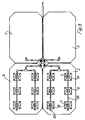
- Fig. 3 is a plan view of a layout of an effluent treatment system according to the invention,
- Fig. 4 is a cross-sectional view on the line Y - Y in Fig. 3,
- Fig. 5 is a top plan view on an enlarged scale of one module of the treatment system of Fig. 3,
- Fig. 6 is a side view of the module of Fig. 5,
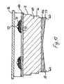
- Fig. 7 is a side cross sectional view of a module,
- Fig. 8 is a top plan view of one distribution portion of one module,
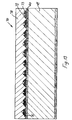
- Fig. 9 is a cross-sectional view on the line Z - Z in Fig. 8,
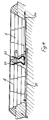
- Fig. 10 is an underneath plan view of the distribution portion of Fig. 8,
- Fig. 11 is a plan view of another system according to the invention,
- Fig. 12 is a side cross-sectional view of a module of the system of Fig. 11,
- Fig. 13 is a schematic side cross-sectional view of another effluent treatment system according to the invention, and
- Fig. 14 is a diagrammatic view of another effluent treatment system, in use.
- Referring to the drawings and initially to Figs. 1 to 10 thereof there is illustrated an effluent treatment system according to the invention and indicated generally by the
reference numeral 1. Thesystem 1 is in this case for treating treated effluent from aseptic tank 50 which receives effluent from asingle dwelling 51. Thesystem 1 may be fed by pumping using apump 52 as illustrated in Fig. 1 or gravity fed as illustrated in Fig. 2. Thetreatment system 1 is in this case of modular construction and comprises a number ofbiological treatment modules 2. In this case there are four modules arranged as illustrated in Fig. 5. - Referring particularly to Figs. 4 to 7 each of the
modules 2 comprises a tank orcontainer 5 for abiological treatment medium 41, eachcontainer 5 having inlets 7 for effluent from aseptic tank 50 andoutlets 13 for filtered effluent. Thecontainer 5 is in this case closed by an airpermeable lid 16 comprising acover 16 which carries a layer ofpeat fibre material 17 to reduce odour. The odour control layer of fibrous material may be held in place by a lower plastics mesh layer and, if necessary to retain the fibrous material in place, also an upper plastics mesh layer. Means for distributing effluent over thefilter medium 41 of eachmodule 2 in this case comprises fourrosette distributors 10, one of which is illustrated in detail in Figs. 8 to 10. Eachdistributor 10 has acentral inlet 12 and a plurality of spaced-apartopenings 18 which are fed from thecommon inlet 12 by gravity flow. The distributor is in this case of moulded polystyrene construction and thedistributors 10 rest on top of thetreatment medium 41 as illustrated in Fig. 7. - In use, the
modules 2 are installed partially below ground level 15 as illustrated in Fig. 2 and effluent from a septic tank may be pumped from a sump through amain inlet pipe 20 located below ground level which is connected to a distribution pipe network to thetreatment medium 41 byrisers 26. Alternatively, the effluent flows by gravity to the treatment plant. Thedistribution pipe network 25 includesoutlet openings 28 which discharge effluent to thecentral inlets 12 of therosette distributors 10 as will be apparent from Fig. 5. The main upperdistribution pipe network 25 is hung by plastic or wire tiedjoints 30 from support braces 32. - As will be apparent from Figs. 4, 6 and 7 the
outlets 13 are provided by a plurality of spaced-apart drain holes 34 extending around the base of thecontainer 5 and which discharge to aeffluent collection pipe 35 through which the treated effluent passes by gravity flow to a discharge point. It will be noted that the outlets from the treatment system are provided withfilters 60 which in this case are of organic heather material or stone chippings of 18mm average size. - It will be appreciated that the
treatment plant 1 is of modular construction and may be sized to accommodate a desired flow of effluent by including more or less modules than those illustrated. The size and configuration of the treatment plant will depend on a number of factors including the quantity and quality of the effluent to be treated. Typically effluent from a septic tank will be discharged into a sump and pumped into the treatment plant, typically at a domestic rate of approximately 750 litres per day. Normally, the discharge would be applied in approximately eight pumping batches and the pumping would be float switch controlled. For larger systems (i.e. multiple house) the inlet pump may be controlled by level probes in the sump and/or perhaps by a timing mechanism. - In all cases the effluent treated by the system of the invention has already passed through a primary treatment step, for example through a septic tank, which removes solids and provides anaerobic treatment of sewage-type effluent.
- The peat used was Von Post approximately H₁ grade young Sphagnum peat which in the case of the examples given below contained approximately 70% Sphagnum and 30% humic material by volume. The Sphagnum fraction contained approximately:
- 30%
- S. imbricatum
- 15%
- S. acutifolium
- 5%
- S. cuspitatum
- Young Sphagnum peat, by which is meant Sphagnum peat which is less than 2,500 years old, is preferred because of its high water-holding capacity which is generally over ten times its dry weight and has over 95% of its volume in the form of free space or pores.
- Preferably the peat used is Von Post grade H₁ to H₃, most preferably grade H₁. The Von Post humification scale is a scale describing peat in varying stages of decomposition. H₁ is the least unhumified peat which upon pressing in the hand, gives off colourless clear water. Grade H₂ is slightly humified peat which upon pressing in the hand gives off almost clear but yellow-brown water. Grade H₃ is very little humified peat which, upon pressing, gives off distinctly turbid water but the residue is not mushy.
- Preferably the fibrous material is a peat fibre which comprises fragments or pieces of plant tissues excluding live roots that retains the recognisable cellular structure of the plant from which it originated.
- In the examples given below the fibrous material used consisted mainly of root residues or eriophorum (cottongrass or bog cotton) plants extracted from bog peats and containing approximately 50% fibre, 40% humic material and 10% sphagnum. The sphagnum fraction consisted of S. imbricatum, S. acutifolium and S. cuspitatum.
- The peat and fibrous material are homogenously mixed using a volumetric measure and mixing by hand-fork or alternatively a volumetric measure and a mechanical mixer in the ratios indicated below to provide the biological treatment media.
- In more detail, and referring particularly to Fig. 7 each
container 5 contains abiological treatment medium 41 comprising a homogenous mixture of peat and organic fibre as described above to a depth of from 0.5 to 1 metre, preferably approximately 0.75 metres. The medium 41 is covered by alayer 40 of eriophorum peat fibre for distributing the effluent. An additional layer 44 of eriophorum peat fibre is provided below the biological treatment medium to induce flow of treated effluent to theoutlets 34. - Referring to Figs. 11 and 12 there is illustrated another effluent treatment system according to the invention which is similar to the system described above with reference to Figs. 3 and 12. In this case the means for distributing effluent across the surface of the medium 41 comprises a plurality of
pipes 72 each having a plurality of spaced-apart outlet holes 73 for effluent. Alayer 75 of stone chippings is provided underneath and around thepipe outlets 73 for spreading and distributing effluent to be treated. - Referring to Fig. 13 there is illustrated an alternative
effluent treatment system 70 which is similar to thesystem 1 described above. In this case thecontainer 5 includes abiological treatment medium 41, anupper fibre layer 40 and alower fibre layer 46, as before. In this case the means for distributing effluent across the surface of the medium 41 comprises a plurality ofpipes 72 each having a plurality of spaced-apart outlet holes 73 for effluent. Alayer 75 of stone chippings is provided underneath and around thepipe outlets 73 for spreading and distributing effluent to be treated. For odour control and to eliminate light thepipes 72 andstone chippings 75 are covered with abed 78 of peat with or without fibre. - We have found that this system offers the advantage of simplicity of assembly and cost effectiveness because less parts are required.
- Referring to Fig. 14 there is illustrated another
effluent treatment system 80 which in this case is not of modular construction but comprises a single container 81 or silo fed with effluent by apump 82 from a primary effluent treatment source, in this case aseptic tank 83. The container 81 contains a biologically active medium of the type described above with an upper peat fibre layer for distribution of effluent and a lower peat fibre layer for inducing outlet flow. The area of the bed is dictated by the volume of effluent to be handled. - An effluent treatment system was installed at a municipal site to treat effluent from a primary effluent treatment in which a substantial proportion of the solids had been removed. A single module of the type described above with reference to Figs. 3 to 10 of size 2.5 metres by 1.4 metres was used. The depth of the biologically active peat/fibre homogenous mixture was approximately 0.75 metres. The biological treatment medium was an 80/20 peat fibre ratio in a homogenous mixture at 50% compaction. The system was loaded at 7 centimetres per day in 10 pumpings. A rosette type distributor was used.
- A summary of the results in set out below.
- It will be noted that
- an average reduction in biological oxygen demand (B.O.D.) of 97%,
- an average reduction in total suspended solids (T.S.S.) of 93%, and
- an average reduction in coliforms of over 99% was achieved.
- Because a peat/fibre mixture was used no ponding was observed even at the relatively high loading of 7cm/day used.

- Example 1 was duplicated using a biological treatment medium having a 50/50 peat/fibre ratio in a homogenous mixture at 50% compaction.
- A summary of the results is set out below.
- It will be noted that
- an average reduction in B.O.D. of 96%,
- an average reduction in T.S.S. of 92%, and
- an average reduction in coliforms of greater than 99% was achieved.
- No ponding was observed. The drainability of the medium was improved by incorporating additional fibre than in Example 1 without a significant decrease in the biological treatment performance of the system.

- A treatment system was installed at an industrial site to treat effluent from septic tanks and large yard run-off, the latter of which includes animal food debris.
- A system similar to that illustrated in Fig. 12 was used using a single housing having an area of 50 square metres.
- The system used an 20/80 peat/fibre ratio at a compaction of 50% and was loaded at 15cm/day initially. This was increased to 20cm/day from 22 August 1989.
- A summary of the results is set out below.

- It will be noted that
- an average reduction in B.O.D. of 84%, and
- an average reduction in T.S.S. of 89% was achieved.
- an average reduction in Ammonia of 60% was achieved.
- The loadings applied were extremely high, however, the unit performed well and no ponding was observed because of the incorporation of a relatively large proportion of fibre in the biologically active treatment medium.
Claims (21)
- An effluent treatment system (1, 70, 80) comprising:-
a container (5) having an upper inlet for effluent and a lower outlet for treated effluent; and
a biological effluent treatment medium (6, 41) in the container (5);
whereby
the effluent is effluent which has passed through a septic tank (50) to remove a substantial portion of solids, and
characterised in that
the biological treatment medium (41) comprises a homogeneous mixture of biologically active peat, and a fibrous peat material comprising the root residues of eriophorum (cotton grass) plants extracted from bog peat. - A system as claimed in claim 1 characterised in that the ratio of peat to fibrous material in the medium (41) is in the range of 10:90 to 90:10 by volume.
- A system as claimed in claim 2 characterised in that the ratio is from 20:80 to 80:20 by volume.
- A system as claimed in claim 2 or 3 characterised in that the ratio is approximately 50:50.
- A system as claimed in any preceding claim characterised in that the biologically active peat is a young Sphagnum peat.
- A system as claimed in claim 5 characterised in that the peat is of a Von Post humification scale of from H₁ to H₃ grade.
- A system as claimed in claim 5 or 6 characterised in that the peat is of a Von Post humification scale of H₁ grade.
- A system as claimed in any preceding claim characterised in that the mixture is compacted by from 20% to 75% by volume.
- A system as claimed in claim 8 characterised in that the mixture is compacted by from 30% to 60% by volume.
- A system as claimed in claim 8 or 9 characterised in that the mixture is compacted approximately 50% by volume.
- A system as claimed in any preceding claim characterised in that an upper effluent distribution medium (40) is provided above the biological effluent treatment medium.
- A system as claimed in claim 11 characterised in that the distribution medium (40) is an organic fibrous material.
- A system as claimed in any preceding claim characterised in that a lower outlet flow inducing medium (44) is provided below the biological effluent treatment medium (41) at or adjacent to the effluent outlet.
- A system as claimed in claim 13 characterised in that the outlet flow inducing medium (44) is of an organic fibrous material.
- A system as claimed in any preceding claim characterised in that the depth of the effluent treatment medium (41) is in the range 0.5 to 1.0 metres.
- A system as claimed in claim 15 characterised in that the depth of the medium is approximately 0.75 metres.
- A system as claimed in any preceding claim characterised in that the surface area of the effluent treatment medium is at least 7 square metres for an hydraulic loading of in the order of 7cm to 15cm per day of effluent.
- A system as claimed in any preceding claim characterised in that the container (5) has a top opening closed by an air permeable lid (16) comprising a perforated cover having an odour control layer of fibrous material (17).
- A system as claimed in any preceding claim characterised in that the system includes means (10,72) for distributing effluent across the surface of the effluent treatment medium.
- A system as claimed in claim 19 characterised in that the means for distributing effluent across the surface of the effluent treatment medium (41) comprises at least one pipe (72) extending above the treatment medium, the pipe having a plurality of spaced-apart outlet holes (73), a layer of stone chippings (75) being provided underneath the pipe outlets, and a layer of peat material (78) being provided above the stone chippings (75) to spread and distribute effluent to be treated.
- A system as claimed in any preceding claim characterised in that the container (5) is of a modular form, a number of containers (5) being joined together and the effluent to be treated being spread across the containers (5), in parallel flow.
Priority Applications (1)
| Application Number | Priority Date | Filing Date | Title |
|---|---|---|---|
| AT90301468T ATE96128T1 (en) | 1989-02-10 | 1990-02-12 | SYSTEM FOR WASTE TREATMENT. |
Applications Claiming Priority (2)
| Application Number | Priority Date | Filing Date | Title |
|---|---|---|---|
| IE243589 | 1989-02-10 | ||
| IE892435A IE892435L (en) | 1989-02-10 | 1989-02-10 | Translation of polycistronic messages in eucaryotic cells |
Publications (2)
| Publication Number | Publication Date |
|---|---|
| EP0382579A1 EP0382579A1 (en) | 1990-08-16 |
| EP0382579B1 true EP0382579B1 (en) | 1993-10-20 |
Family
ID=11034784
Family Applications (1)
| Application Number | Title | Priority Date | Filing Date |
|---|---|---|---|
| EP19900301468 Expired - Lifetime EP0382579B1 (en) | 1989-02-10 | 1990-02-12 | An effluent treatment system |
Country Status (10)
| Country | Link |
|---|---|
| US (1) | US5049265A (en) |
| EP (1) | EP0382579B1 (en) |
| JP (1) | JPH0394893A (en) |
| AT (1) | ATE96128T1 (en) |
| AU (1) | AU623974B2 (en) |
| CA (1) | CA2009752C (en) |
| DE (1) | DE69003966T2 (en) |
| ES (1) | ES2047841T3 (en) |
| GB (1) | GB2229433B (en) |
| IE (1) | IE892435L (en) |
Families Citing this family (41)
| Publication number | Priority date | Publication date | Assignee | Title |
|---|---|---|---|---|
| IE892435L (en) * | 1989-02-10 | 1990-01-29 | Zymogenetics Inc | Translation of polycistronic messages in eucaryotic cells |
| US5707513A (en) * | 1992-05-13 | 1998-01-13 | Jowett; E. Craig | Wastewater treatment method and apparatus |
| US6153094A (en) * | 1992-05-13 | 2000-11-28 | E. Craig Jowett | Wastewater treatment method and apparatus |
| DE4394475T1 (en) * | 1992-09-14 | 1995-10-19 | Dowmus Pty Ltd | Waste disposal and treatment method and apparatus |
| WO1994013590A1 (en) * | 1992-12-16 | 1994-06-23 | Bord Na Mona | An effluent treatment system |
| US5389248B1 (en) * | 1993-05-21 | 1998-09-29 | Tour Mcgill College | Bioreactor for biological treatment of contaminated water |
| CA2139554C (en) * | 1994-01-06 | 2008-09-09 | E. Craig Jowett | Waste water treatment method and apparatus |
| NO302290B1 (en) * | 1994-12-27 | 1998-02-16 | Bakelittfab As | Filtration foam and gray water purification devices |
| CA2139247C (en) * | 1994-12-29 | 1999-01-19 | Stephen G. Simmering | Sewage treatment system using peat and a constructed wetland |
| AUPN222395A0 (en) * | 1995-04-07 | 1995-05-04 | Dowmus Pty Ltd | Waste water purification system |
| CA2149202C (en) * | 1995-05-11 | 2002-01-29 | Patrick Goupil | Treatment system for treating waste water |
| US5792355A (en) * | 1995-09-15 | 1998-08-11 | Desjardins; Gaetan | Process for treating waste water |
| CA2166666C (en) * | 1996-01-05 | 2005-12-06 | Richard W. Connelly | Sewer system |
| US5958239A (en) * | 1997-01-15 | 1999-09-28 | Sing; Peter | Multi-level septic drainfields |
| US6123840A (en) * | 1997-05-06 | 2000-09-26 | Sanyo Electric. Co., Ltd. | Organic waste water treating apparatus having treating layer and auxiliary layer |
| US6514410B1 (en) * | 1997-09-23 | 2003-02-04 | Charles J. Gantzer | Odor control apparatus for facultative lagoon |
| US6287469B1 (en) * | 1997-10-17 | 2001-09-11 | Ashco-A-Corporation | Home wastewater treatment plant |
| US6436288B1 (en) | 1999-02-08 | 2002-08-20 | Mississippi State University | Bast medium biological reactor treatment system for remediation and odor suppression of organic waste streams |
| US6620321B2 (en) | 1999-12-30 | 2003-09-16 | Edward R. Festa | Biofilter system and method for treating wastewater |
| US6851891B2 (en) | 2000-02-03 | 2005-02-08 | Baumgartner Environics, Inc. | Organic slurry storage basin cover |
| US6659688B2 (en) | 2000-02-03 | 2003-12-09 | Baumgartner Environics, Inc. | Organic slurry basin storage cover and method of fabricating and deploying cover |
| CA2314689C (en) * | 2000-04-10 | 2003-09-09 | Le Groupe Berger Ltee/Berger Group Ltd. | Biofiltering system for treating wastewater effluent |
| US6372128B1 (en) * | 2000-05-16 | 2002-04-16 | LE GROUP BERGER LTéE/BERGER GROUP LTD. | Biofiltering device for treating wastewater |
| CA2314545A1 (en) | 2000-07-13 | 2002-01-13 | Jacek Mlynarek | Directional packing for filtration and biofiltration system |
| WO2002028510A2 (en) * | 2000-10-06 | 2002-04-11 | Odor Control Systems, Inc. | Lagoon covers providing multi-stage waste treatment |
| US6932540B2 (en) * | 2000-10-06 | 2005-08-23 | 3-R Foam, Inc. | Permeable water reservoir covers |
| US6428691B1 (en) * | 2000-11-06 | 2002-08-06 | Charles Wofford | Biological waste water treatment system |
| US6773595B2 (en) | 2001-03-29 | 2004-08-10 | Charles J. Gantzer | Compartmentalized facultative lagoon and method of creating and maintaining such a lagoon |
| US7160460B2 (en) * | 2001-04-13 | 2007-01-09 | Quanics, Inc. | System and method for treating wastewater using coir filter |
| CA2387777C (en) | 2002-05-28 | 2008-04-01 | Ms Filter Inc. | Potable water treatment plant and method of maintaining same |
| CA2405062A1 (en) * | 2002-09-20 | 2004-03-20 | Denis Pettigrew | Filter pack containing coconut husk |
| US7510649B1 (en) * | 2004-01-09 | 2009-03-31 | Ronald Lavigne | Top loading vertical flow submerged bed wastewater treatment system |
| GB2425306A (en) * | 2004-03-30 | 2006-10-25 | New Water Pty Ltd | Water treatment |
| US7497947B2 (en) * | 2004-04-14 | 2009-03-03 | Embro Corporation | Devices for water treatment |
| US7309434B2 (en) * | 2004-06-28 | 2007-12-18 | Potts David A | Apparatus and method for wastewater treatment |
| US7407577B2 (en) * | 2004-09-17 | 2008-08-05 | Curt Kerns | Tertiary filter septic system and method |
| US8685235B2 (en) * | 2009-02-04 | 2014-04-01 | Vladimir Petrovich Kolesnjkov | Integrated sewage treatment plant |
| EP2753422A1 (en) | 2011-09-07 | 2014-07-16 | Embro Corporation | Use of moss to reduce disinfection by-products in water treated with disinfectants |
| US9795809B2 (en) | 2013-12-23 | 2017-10-24 | Embro Corporation | Use of moss to improve dental health |
| FR3039078B1 (en) | 2015-07-20 | 2019-08-16 | Eparco | COMPACT BIOFILTER AND INSTALLATION FOR THE TREATMENT OF SEPTIC DOMESTIC EFFLUENTS |
| FR3049297B1 (en) * | 2016-03-25 | 2021-09-24 | Jean Pierre Dautais | LIQUID DISTRIBUTION DEVICE ON A FILTRATION SURFACE |
Family Cites Families (28)
| Publication number | Priority date | Publication date | Assignee | Title |
|---|---|---|---|---|
| US3123555A (en) * | 1964-03-03 | Automatic sewage disposal for individual homes and buildings | ||
| US877569A (en) * | 1906-12-29 | 1908-01-28 | Arthur I Joseph | Apparatus for treating sewage. |
| FR386174A (en) * | 1908-01-13 | 1908-06-05 | Bernard Bezault | Septic tank and filter and deodorants |
| US968015A (en) * | 1909-10-25 | 1910-08-23 | Boyd Wilkie | Apparatus for filtering sewage. |
| US1805852A (en) * | 1929-03-21 | 1931-05-19 | Robert D Simpson | Liquid distributor |
| US2220859A (en) * | 1937-10-05 | 1940-11-05 | William N Bispham | Method and apparatus for treating sewage |
| GB502530A (en) * | 1938-07-30 | 1939-03-20 | Cecil John Dekema | Improvements in or relating to the progressive purification of biologically impure liquids |
| DE1156712B (en) * | 1959-02-09 | 1963-10-31 | Rudolf Lautrich | Drip heads for the biological purification of waste water |
| US3325016A (en) * | 1964-08-18 | 1967-06-13 | Babcock & Wilcox Dampfkessel | Filter earths |
| JPS4844622U (en) * | 1971-09-25 | 1973-06-11 | ||
| JPS5512320B2 (en) * | 1971-09-30 | 1980-04-01 | ||
| US3825119A (en) * | 1973-03-08 | 1974-07-23 | K Rost | Waste water treatment unit |
| US3894355A (en) * | 1974-01-28 | 1975-07-15 | Charles H Carothers | Method and means for automatic field growing of crops using solid and liquid waste |
| US3933641A (en) * | 1974-03-04 | 1976-01-20 | Environs Engineering Enterprises, Inc. | Sewage treatment and recycling system |
| FR2337106A1 (en) * | 1975-12-30 | 1977-07-29 | Serted | Treatment of waste waters with fossilised carbon bed - which is divided into working and resting zones |
| JPS5452861A (en) * | 1977-10-03 | 1979-04-25 | Tech Res & Dev Inst Of Japan Def Agency | Treatment of human waste in a closed ststem |
| JPS5534186A (en) * | 1978-09-04 | 1980-03-10 | Tadashi Niimi | Denitrification acceleration method from foul water and apparatus thereof |
| US4251359A (en) * | 1979-05-21 | 1981-02-17 | C2 F Investment Company | On-site wastewater treatment system |
| CH653978A5 (en) * | 1981-10-08 | 1986-01-31 | Sulzer Ag | SYSTEM FOR THE BIOLOGICAL PURIFICATION OF WATER OR WASTEWATER. |
| US4465594A (en) * | 1982-09-29 | 1984-08-14 | Rein Laak | Sewage system for the treatment of segregated domestic waste water |
| JPS59112816A (en) * | 1982-12-17 | 1984-06-29 | Unitika Ltd | Preparation of fiber lump |
| NL8303031A (en) * | 1983-08-31 | 1985-03-18 | Tongeren Ingbureau Bv Van | METHOD AND APPARATUS FOR BIOLOGICAL FILTRATION OF GASES. |
| DE3402697A1 (en) * | 1984-01-26 | 1985-08-01 | Bayer Ag, 5090 Leverkusen | USE OF HYDROPHILIC, HIGH-FILLED POLYURETHANE MASSES FOR BIOLOGICAL WASTE WATER TREATMENT |
| JPH0611439B2 (en) * | 1984-11-30 | 1994-02-16 | 共和化工株式会社 | Biological treatment method of sewage |
| DE3529668A1 (en) * | 1985-08-20 | 1987-02-26 | Blum Albert | CLEANING DEVICE |
| US4678582A (en) * | 1986-01-24 | 1987-07-07 | Lavigne Ronald L | Treatment system for landfill leachate |
| AT390783B (en) * | 1987-04-10 | 1990-06-25 | Solvay Ebenseer | METHOD FOR DEGRADING LIGNIN AND / OR CHLORINE ORGANIC COMPOUNDS WITH WATERWATER MUSHROOMS |
| IE892435L (en) * | 1989-02-10 | 1990-01-29 | Zymogenetics Inc | Translation of polycistronic messages in eucaryotic cells |
-
1989
- 1989-02-10 IE IE892435A patent/IE892435L/en not_active IP Right Cessation
-
1990
- 1990-02-09 CA CA 2009752 patent/CA2009752C/en not_active Expired - Lifetime
- 1990-02-12 DE DE90301468T patent/DE69003966T2/en not_active Expired - Lifetime
- 1990-02-12 AU AU49346/90A patent/AU623974B2/en not_active Expired
- 1990-02-12 US US07/478,409 patent/US5049265A/en not_active Expired - Lifetime
- 1990-02-12 ES ES90301468T patent/ES2047841T3/en not_active Expired - Lifetime
- 1990-02-12 GB GB9003084A patent/GB2229433B/en not_active Expired - Lifetime
- 1990-02-12 AT AT90301468T patent/ATE96128T1/en not_active IP Right Cessation
- 1990-02-12 EP EP19900301468 patent/EP0382579B1/en not_active Expired - Lifetime
- 1990-02-13 JP JP2032291A patent/JPH0394893A/en active Pending
Also Published As
| Publication number | Publication date |
|---|---|
| ES2047841T3 (en) | 1994-03-01 |
| AU623974B2 (en) | 1992-05-28 |
| CA2009752C (en) | 1998-09-22 |
| GB2229433B (en) | 1992-09-30 |
| CA2009752A1 (en) | 1990-08-10 |
| DE69003966D1 (en) | 1993-11-25 |
| GB2229433A (en) | 1990-09-26 |
| AU4934690A (en) | 1990-08-16 |
| DE69003966T2 (en) | 1994-02-10 |
| EP0382579A1 (en) | 1990-08-16 |
| JPH0394893A (en) | 1991-04-19 |
| US5049265A (en) | 1991-09-17 |
| GB9003084D0 (en) | 1990-04-11 |
| IE892435L (en) | 1990-01-29 |
| ATE96128T1 (en) | 1993-11-15 |
Similar Documents
| Publication | Publication Date | Title |
|---|---|---|
| US5049265A (en) | Effluent treatment system | |
| EP0029066B1 (en) | On-site wastewater treatment system | |
| US4824572A (en) | Method and apparatus for treating household waste water | |
| US5337516A (en) | Treatment of polluted water using wetland plants in a floating habitat | |
| CA2139247C (en) | Sewage treatment system using peat and a constructed wetland | |
| US7320752B2 (en) | Integrated hydroponic and wetland wastewater treatment systems and associated methods | |
| US5156741A (en) | Wastewater treatment system and method | |
| CN101691270B (en) | Assembled packing artificial vertical subsurface flow wetland unit, application thereof and sewage treatment process | |
| US2795542A (en) | Disposal of septic tank effluent and the like | |
| US6264838B1 (en) | On site waste water recycling system | |
| EP0836585B1 (en) | Treatment system for treating waste water | |
| US6620321B2 (en) | Biofilter system and method for treating wastewater | |
| CN212640065U (en) | Vertical rural domestic sewage treatment equipment | |
| Liénard et al. | Treatment of sludge from septic tanks in a reed-bed filters pilot plant | |
| KR100237041B1 (en) | Apparatus for treating wastewater with trickling filter charged microbe carrier in porous box | |
| IE63687B1 (en) | An effluent treatment system | |
| JP3796720B2 (en) | Human waste purification device | |
| WO1993023339A1 (en) | Wastewater treatment method and apparatus | |
| GB2453149A (en) | A Reed Bed formed of Reed bed modules | |
| RU2119894C1 (en) | Gear to treat domestic sewage | |
| Dawson | High hopes for cattails | |
| WO1994013590A1 (en) | An effluent treatment system | |
| Lesikar | Sand filter | |
| WO1996025374A1 (en) | Method and devices for biological purification of waste | |
| Mann | Sewage treatment for small communities |
Legal Events
| Date | Code | Title | Description |
|---|---|---|---|
| PUAI | Public reference made under article 153(3) epc to a published international application that has entered the european phase |
Free format text: ORIGINAL CODE: 0009012 |
|
| AK | Designated contracting states |
Kind code of ref document: A1 Designated state(s): AT BE CH DE DK ES FR GB GR IT LI LU NL SE |
|
| 17P | Request for examination filed |
Effective date: 19901228 |
|
| 17Q | First examination report despatched |
Effective date: 19910917 |
|
| RBV | Designated contracting states (corrected) |
Designated state(s): AT BE CH DE DK ES FR GR IT LI LU NL SE |
|
| GRAA | (expected) grant |
Free format text: ORIGINAL CODE: 0009210 |
|
| AK | Designated contracting states |
Kind code of ref document: B1 Designated state(s): AT BE CH DE DK ES FR GR IT LI LU NL SE |
|
| PG25 | Lapsed in a contracting state [announced via postgrant information from national office to epo] |
Ref country code: DK Effective date: 19931020 Ref country code: SE Effective date: 19931020 Ref country code: BE Effective date: 19931020 Ref country code: NL Effective date: 19931020 |
|
| REF | Corresponds to: |
Ref document number: 96128 Country of ref document: AT Date of ref document: 19931115 Kind code of ref document: T |
|
| RAP2 | Party data changed (patent owner data changed or rights of a patent transferred) |
Owner name: BORD NA MONA |
|
| REF | Corresponds to: |
Ref document number: 69003966 Country of ref document: DE Date of ref document: 19931125 |
|
| ITF | It: translation for a ep patent filed | ||
| PG25 | Lapsed in a contracting state [announced via postgrant information from national office to epo] |
Ref country code: CH Effective date: 19940228 Ref country code: LU Free format text: LAPSE BECAUSE OF NON-PAYMENT OF DUE FEES Effective date: 19940228 Ref country code: LI Effective date: 19940228 |
|
| REG | Reference to a national code |
Ref country code: ES Ref legal event code: FG2A Ref document number: 2047841 Country of ref document: ES Kind code of ref document: T3 |
|
| ET | Fr: translation filed | ||
| K1C1 | Correction of patent application (title page) published |
Effective date: 19900816 |
|
| REG | Reference to a national code |
Ref country code: GR Ref legal event code: FG4A Free format text: 3010518 |
|
| NLV1 | Nl: lapsed or annulled due to failure to fulfill the requirements of art. 29p and 29m of the patents act | ||
| PLBE | No opposition filed within time limit |
Free format text: ORIGINAL CODE: 0009261 |
|
| STAA | Information on the status of an ep patent application or granted ep patent |
Free format text: STATUS: NO OPPOSITION FILED WITHIN TIME LIMIT |
|
| 26N | No opposition filed | ||
| REG | Reference to a national code |
Ref country code: CH Ref legal event code: PL |
|
| PGFP | Annual fee paid to national office [announced via postgrant information from national office to epo] |
Ref country code: ES Payment date: 20080331 Year of fee payment: 19 |
|
| PGFP | Annual fee paid to national office [announced via postgrant information from national office to epo] |
Ref country code: AT Payment date: 20090227 Year of fee payment: 20 |
|
| PGFP | Annual fee paid to national office [announced via postgrant information from national office to epo] |
Ref country code: GR Payment date: 20081223 Year of fee payment: 20 |
|
| PGFP | Annual fee paid to national office [announced via postgrant information from national office to epo] |
Ref country code: DE Payment date: 20090429 Year of fee payment: 20 Ref country code: IT Payment date: 20090226 Year of fee payment: 20 |
|
| PGFP | Annual fee paid to national office [announced via postgrant information from national office to epo] |
Ref country code: FR Payment date: 20090211 Year of fee payment: 20 |
|
| REG | Reference to a national code |
Ref country code: ES Ref legal event code: FD2A Effective date: 20090213 |
|
| PG25 | Lapsed in a contracting state [announced via postgrant information from national office to epo] |
Ref country code: ES Free format text: LAPSE BECAUSE OF NON-PAYMENT OF DUE FEES Effective date: 20090213 |
|
| PG25 | Lapsed in a contracting state [announced via postgrant information from national office to epo] |
Ref country code: DE Free format text: LAPSE BECAUSE OF EXPIRATION OF PROTECTION Effective date: 20100212 |