EP0382513A2 - Panel manufacture and processors for use therein - Google Patents
Panel manufacture and processors for use therein Download PDFInfo
- Publication number
- EP0382513A2 EP0382513A2 EP90301312A EP90301312A EP0382513A2 EP 0382513 A2 EP0382513 A2 EP 0382513A2 EP 90301312 A EP90301312 A EP 90301312A EP 90301312 A EP90301312 A EP 90301312A EP 0382513 A2 EP0382513 A2 EP 0382513A2
- Authority
- EP
- European Patent Office
- Prior art keywords
- blank
- article
- edge
- ultraviolet
- groove
- Prior art date
- Legal status (The legal status is an assumption and is not a legal conclusion. Google has not performed a legal analysis and makes no representation as to the accuracy of the status listed.)
- Withdrawn
Links
Images


Classifications
-
- A—HUMAN NECESSITIES
- A47—FURNITURE; DOMESTIC ARTICLES OR APPLIANCES; COFFEE MILLS; SPICE MILLS; SUCTION CLEANERS IN GENERAL
- A47B—TABLES; DESKS; OFFICE FURNITURE; CABINETS; DRAWERS; GENERAL DETAILS OF FURNITURE
- A47B83/00—Combinations comprising two or more pieces of furniture of different kinds
- A47B83/001—Office desks or work-stations combined with other pieces of furniture, e.g. work space management systems
-
- A—HUMAN NECESSITIES
- A47—FURNITURE; DOMESTIC ARTICLES OR APPLIANCES; COFFEE MILLS; SPICE MILLS; SUCTION CLEANERS IN GENERAL
- A47B—TABLES; DESKS; OFFICE FURNITURE; CABINETS; DRAWERS; GENERAL DETAILS OF FURNITURE
- A47B95/00—Fittings for furniture
- A47B95/04—Keyplates; Ornaments or the like
- A47B95/043—Protecting rims, buffers or the like
-
- A—HUMAN NECESSITIES
- A47—FURNITURE; DOMESTIC ARTICLES OR APPLIANCES; COFFEE MILLS; SPICE MILLS; SUCTION CLEANERS IN GENERAL
- A47B—TABLES; DESKS; OFFICE FURNITURE; CABINETS; DRAWERS; GENERAL DETAILS OF FURNITURE
- A47B96/00—Details of cabinets, racks or shelf units not covered by a single one of groups A47B43/00 - A47B95/00; General details of furniture
- A47B96/20—Furniture panels or like furniture elements
- A47B96/201—Edge features
-
- A—HUMAN NECESSITIES
- A47—FURNITURE; DOMESTIC ARTICLES OR APPLIANCES; COFFEE MILLS; SPICE MILLS; SUCTION CLEANERS IN GENERAL
- A47B—TABLES; DESKS; OFFICE FURNITURE; CABINETS; DRAWERS; GENERAL DETAILS OF FURNITURE
- A47B96/00—Details of cabinets, racks or shelf units not covered by a single one of groups A47B43/00 - A47B95/00; General details of furniture
- A47B96/20—Furniture panels or like furniture elements
- A47B96/205—Composite panels, comprising several elements joined together
- A47B96/206—Composite panels, comprising several elements joined together with laminates comprising planar, continuous or separate layers
-
- B—PERFORMING OPERATIONS; TRANSPORTING
- B29—WORKING OF PLASTICS; WORKING OF SUBSTANCES IN A PLASTIC STATE IN GENERAL
- B29C—SHAPING OR JOINING OF PLASTICS; SHAPING OF MATERIAL IN A PLASTIC STATE, NOT OTHERWISE PROVIDED FOR; AFTER-TREATMENT OF THE SHAPED PRODUCTS, e.g. REPAIRING
- B29C70/00—Shaping composites, i.e. plastics material comprising reinforcements, fillers or preformed parts, e.g. inserts
- B29C70/68—Shaping composites, i.e. plastics material comprising reinforcements, fillers or preformed parts, e.g. inserts by incorporating or moulding on preformed parts, e.g. inserts or layers, e.g. foam blocks
- B29C70/74—Moulding material on a relatively small portion of the preformed part, e.g. outsert moulding
- B29C70/76—Moulding on edges or extremities of the preformed part
- B29C70/763—Moulding on edges or extremities of the preformed part the edges being disposed in a substantial flat plane
-
- A—HUMAN NECESSITIES
- A47—FURNITURE; DOMESTIC ARTICLES OR APPLIANCES; COFFEE MILLS; SPICE MILLS; SUCTION CLEANERS IN GENERAL
- A47B—TABLES; DESKS; OFFICE FURNITURE; CABINETS; DRAWERS; GENERAL DETAILS OF FURNITURE
- A47B2200/00—General construction of tables or desks
- A47B2200/0001—Tops
- A47B2200/001—Manufacture of table tops
-
- B—PERFORMING OPERATIONS; TRANSPORTING
- B05—SPRAYING OR ATOMISING IN GENERAL; APPLYING FLUENT MATERIALS TO SURFACES, IN GENERAL
- B05D—PROCESSES FOR APPLYING FLUENT MATERIALS TO SURFACES, IN GENERAL
- B05D3/00—Pretreatment of surfaces to which liquids or other fluent materials are to be applied; After-treatment of applied coatings, e.g. intermediate treating of an applied coating preparatory to subsequent applications of liquids or other fluent materials
- B05D3/06—Pretreatment of surfaces to which liquids or other fluent materials are to be applied; After-treatment of applied coatings, e.g. intermediate treating of an applied coating preparatory to subsequent applications of liquids or other fluent materials by exposure to radiation
- B05D3/061—Pretreatment of surfaces to which liquids or other fluent materials are to be applied; After-treatment of applied coatings, e.g. intermediate treating of an applied coating preparatory to subsequent applications of liquids or other fluent materials by exposure to radiation using U.V.
- B05D3/065—After-treatment
- B05D3/067—Curing or cross-linking the coating
-
- B—PERFORMING OPERATIONS; TRANSPORTING
- B29—WORKING OF PLASTICS; WORKING OF SUBSTANCES IN A PLASTIC STATE IN GENERAL
- B29C—SHAPING OR JOINING OF PLASTICS; SHAPING OF MATERIAL IN A PLASTIC STATE, NOT OTHERWISE PROVIDED FOR; AFTER-TREATMENT OF THE SHAPED PRODUCTS, e.g. REPAIRING
- B29C2793/00—Shaping techniques involving a cutting or machining operation
- B29C2793/009—Shaping techniques involving a cutting or machining operation after shaping
-
- Y—GENERAL TAGGING OF NEW TECHNOLOGICAL DEVELOPMENTS; GENERAL TAGGING OF CROSS-SECTIONAL TECHNOLOGIES SPANNING OVER SEVERAL SECTIONS OF THE IPC; TECHNICAL SUBJECTS COVERED BY FORMER USPC CROSS-REFERENCE ART COLLECTIONS [XRACs] AND DIGESTS
- Y10—TECHNICAL SUBJECTS COVERED BY FORMER USPC
- Y10T—TECHNICAL SUBJECTS COVERED BY FORMER US CLASSIFICATION
- Y10T156/00—Adhesive bonding and miscellaneous chemical manufacture
- Y10T156/10—Methods of surface bonding and/or assembly therefor
- Y10T156/1002—Methods of surface bonding and/or assembly therefor with permanent bending or reshaping or surface deformation of self sustaining lamina
- Y10T156/1026—Methods of surface bonding and/or assembly therefor with permanent bending or reshaping or surface deformation of self sustaining lamina with slitting or removal of material at reshaping area prior to reshaping
-
- Y—GENERAL TAGGING OF NEW TECHNOLOGICAL DEVELOPMENTS; GENERAL TAGGING OF CROSS-SECTIONAL TECHNOLOGIES SPANNING OVER SEVERAL SECTIONS OF THE IPC; TECHNICAL SUBJECTS COVERED BY FORMER USPC CROSS-REFERENCE ART COLLECTIONS [XRACs] AND DIGESTS
- Y10—TECHNICAL SUBJECTS COVERED BY FORMER USPC
- Y10T—TECHNICAL SUBJECTS COVERED BY FORMER US CLASSIFICATION
- Y10T156/00—Adhesive bonding and miscellaneous chemical manufacture
- Y10T156/10—Methods of surface bonding and/or assembly therefor
- Y10T156/1002—Methods of surface bonding and/or assembly therefor with permanent bending or reshaping or surface deformation of self sustaining lamina
- Y10T156/1043—Subsequent to assembly
Definitions
- the present invention relates to surface finishes for three dimensional articles, and in particular to a monolithic finishing process and machine for furniture parts, and the like, to the making of panels and to processors for use in the process.
- worksurfaces such as desk tops, tabletops, countertops, writing surfaces, and the like must meet several different design criteria, including smoothness, hardness, durability and appearance.
- One known method for finishing furniture worksurfaces comprises applying a veneer to the top surface of a sheet of substrate material.
- An edge strip is normally applied to the marginal edges of the worksurface, and the veneer and edge strip are blended together.
- Both natural and synthetic veneers have been used quite extensively in such applications, including wood, glass, vinyl, and the like.
- veneer type finishes can be rather expensive to manufacture, and often present inherent design limitations.
- the edge strip imparts a framed appearance to the worksurface that breaks up the lines of the top, and further limits the aesthetics of the associated furniture article.
- Painted finish surfaces for furniture worksurfaces are typically less expensive to manufacture, but are normally rather soft, and tend to mar easily, even when treated with a protective coating, such as lacquer, clear epoxy, or other similar finishes.
- the invention has various aspects which are directed to overcoming some, at least, of the disadvantages.
- a method of making a panel having a coating thereon is characterised by applying a curable liquid base coat material to the two face surfaces and the edges of the sheet and curing the base coat material, applying an ultra-violet-curable liquid protective coat material to one of the face surfaces, the edges and at least part of the other face surface, and exposing the coat to ultra-violet light to cure the coat.
- This aspect of the invention is able to produce a monolithic coating and may be used, for example, for economically making durable furniture panels and the like.
- a blank is formed from a sheet of substrate material to a shape preselected in accordance with a finished panel article.
- a base coat material is provided, which is formulated to adhere to the substrate material.
- a layer of base coat material is applied to at least the top and marginal edge surfaces of the blank, so as to substantially completely cover the same.
- the base coat material is cured to a substantially dry condition to form a base coat.
- a liquid, protective coat material is provided, which cures when exposed to selected ultraviolet radiation, and is formulated to adhere to the base coat material, and provide a mar-resistant coat over at least selected portions of the base coat.
- the protective coat material is applied to at least the top and marginal edge surfaces of the blank to define a protective exterior surface area of the blank which is substantially completely covered with the protective coat material.
- a continuous feed, ultraviolet processor is provided for selectively curing the protective coat material.
- the blank with uncured protective coat material thereon is translated through the ultraviolet processor at a substantially constant rate.
- the UV coated surfaces of the blank are radiated substantially contemporaneously with ultraviolet energy as the blank passes therethrough to partially cure the protective coating material thereon to facilitate forming a selected exterior appearance.
- the UV coated surfaces of the blank are again radiated sub-stantially contemporaneously with ultraviolet energy as the blank continues through the processor to complete curing of the protective coat material to form a mar-resistant, low gloss protective coat over the base coat.
- the base coat and protective coat collectively impart a monolithic appearance to the finished panel article.
- a method of manufacturing a panel having an edge strip characterised by forming in a blank of rigid sheet material a groove adjacent the edge of the blank and extending through the blank from one surface to adjacent the other surface of the blank, placing in the groove a flowable curable edge-protection material, and, after the edge-protection is cured, removing the part of the blank between the groove and the adjacent edge.
- a blank is formed from a sheet of substantially rigid substrate material into a shape preselected in accordance with a selected worksurface article.
- a groove is formed through one surface of the blank located a preselected distance laterally inwardly from the marginal edge of the blank to a depth adjacent to but not through the opposite surface of the blank.
- a curable, liquid edge protection material is provided, which is formulated to adhere to the substrate material, and adapted to provide a durable, dent resistant edge guard for the marginal edge portion of the worksurface article.
- the edge protection material is poured into the groove to a selected level, and is cured in place in the groove to a solid condition.
- the cured edge protection material in the groove, as well as the adjacent surface of the blank are then cut through to create a decoratively shaped, integrally formed protective strip about the marginal edge of the worksurface article.
- a processor for selectively curing photocurable compositions disposed on oppositely oriented surfaces of geometrically solid articles comprises
- a tunnel shaped irradiation chamber configured to receive therethrough a three-dimensional article oriented so as to present upper and lower surfaces, leading and trailing surfaces, and opposite side surfaces, wherein at least portions of three of the surfaces are oppositely oriented and coated with a photocurable composition; means for translating the article with uncured photocurable composition thereon through said irradiation chamber at a substantially constant rate; a first light source disposed generally above said article translating means, and adapted to direct ultraviolet flux directly onto the upper surface of the article as the article translates thereby; a second light source disposed generally below said article translating means, and adapted to direct ultraviolet flux directly onto the lower surface of the article as the article translates thereby; means for orienting said first and second light sources in a manner which directs ultraviolet flux directly onto the leading and trailing surfaces of the article as the article approaches and recedes from said first and second light sources; and means for directing ultraviolet flux from said first and second light sources onto the side surfaces of the article, whereby all of the coated surfaces of the article are ir
- the processor may be used for curing photocurable compositions disposed on geometrically solid articles, such as furniture worksurfaces.
- the processor includes a tunnel shaped irradiation chamber, configured to receive therethrough a three-dimensional article.
- a conveyor such as powered rollers or the like, translate the article with uncured photocurable composition thereon through the irradiation chamber at a substantially constant rate.
- a first UV light source is disposed generally above the article translating mechanism, and is adapted to direct ultraviolet flux onto the upper surface of the article as the article translates thereby.
- a second UV light source is disposed generally below the article translating mechanism, and is adapted to direct ultraviolet flux onto the lower surface of the article as the article translates thereby.
- Ultraviolet flux is also directed onto the leading and trailing edges, as well as the opposite side edges of the article, as the article approaches and recedes from the first and second light sources, such that all of the coated surfaces of the article are irradiated substantially contemporaneously and generally uniformly as the article translates through the irradiation chamber, so as to quickly and evenly cure the photocure composition in a single pass, continuous feed operation.
- a durable, satin like finish which is particularly well adapted for office furniture worksurfaces and the like, and has a unique, soft feel, and a low reflective or low gloss monolithic appearance to the same.
- the surface finish has a very soft appearance and feel which is aesthetically quite pleasing, yet is substantially maintenance free and mar-resistant.
- the surface finish may be used in conjunction with relatively inexpensive substrate materials, such as particle board, flake board and the like, such that an attractive durable worksurface can be manufactured quite economically.
- a wide variety of different base colours may be used with the surface finish, such that the finish can be easily matched and/or coordinated with conventional painted surfaces.
- a unique fill groove edge forming process forms an integral edge strip for variously shaped worksurfaces, without the need for separate moulds.
- the present method and apparatus can be used in conjunction with worksurfaces having different shapes and sizes, and may also be used to cover multi-part top constructions, such as those having a separate marginal edge strip or guard.
- the surface finish imparts a unique monolithic appearance to the part, which makes it look as though the part were chiseled from a solid block of material. Both the process and machine are quite efficient and economical, and particularly well adapted for the proposed use.
- the present invention relates to a process and a machine for surface finishing three-dimensional objects, particularly furniture parts, such as the illustrated worksurfaces, which are generally designated by the reference numeral 1 (Fig. 1).
- the subject surface finish of worksurface 1 is both wear and stain resistant, with a flat, non-glare silky feel, and a unique monolithic appearance.
- the process includes providing a blank 2 (Figs. 15-20) cut from a suitable substrate material.
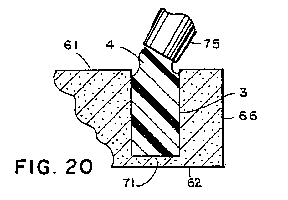
- a groove 3 is formed through one surface of blank 2 about its marginal edge to a depth near the opposite surface of blank 2.
- a liquid edge protection material 4 is poured into groove 3, and fully cured in place. Blank 2 is then cut through at the filled groove 3 by means such as routing or the like, to create a decorative protective strip 5 (Figs.
- UV processor 9 includes powered rollers 10 arranged in spaced apart groups, which convey formed parts 6 through UV processor 9 at a substantially constant speed. UV light sources generally designated by the reference numerals 11 and 12 (Figs.
- rollers 32-34) are located above and below rollers 10, vertically in line with the spaces 13 disposed between adjacent groups of rollers 10, and have selectively oriented reflectors 14 and 15 respectively, which contemporaneously and uniformly radiate all of the UV coated surfaces of the formed part 6, so that the protective material 8 creates a mar-resistant, low gloss protective coating 8, which together with base coat 7, imparts a soft feel, and a monolithic appearance to the finished worksurface 1.
- the present monolithic finishing process can be used in conjunction with a wide variety of different three-dimensional objects.
- the present invention is particularly adapted for use in conjunction with office furniture parts, such as the illustrated worksurfaces 1, which in Figs. 1-3 are shown in conjunction with a unique modular furniture arrangement 25 that is described and claimed in our simultaneously filed European Patent Application No. (reference P15052EP) entitled MODULAR FURNITURE.
- the illustrated modular furniture arrangement 25 (Figs. 1-3) comprises a plurality of individual furniture units 26, each of which is independently supported on the floor 27 of office space 28, and is shaped to cooperate with other related furniture units 26 to form workstations 29.
- Furniture unit 30 is a straight worksurface unit.
- Furniture unit 31 is a corner worksurface unit.
- Furniture unit 32 is a bullet conference unit.
- Furniture unit 33 is a P-top conference unit.
- Furniture unit 34 is a circular table.
- Furniture unit 35 is an extended corner worksurface unit.
- Furniture unit 36 is a half-round, shared conference worksurface unit.
- Furniture unit 37 is an oblong table, and furniture unit 38 is a countertop worksurface.
- Each of the illustrated furniture units 30-38 includes at least one worksurface 1 selected from a wide variety of different shapes and sizes, and two separate supports at the opposite ends of worksurface 1, in the form of either an end panel 42 (Fig. 2), or an intermediate support 43.
- a corner leg 44 is provided at the centre of corner unit 31, bullet conference unit 32, and extended corner unit 35.
- Each of the illustrated modular furniture units 30-38 also includes at least one back panel 45, which covers the front faces or surfaces of the associated furniture unit 26. Back panels 45 have a specially designed, predetermined depth, so as to form a gap or recess 46, which extends along the forward base area of each of the furniture units 26, and is adapted to receive therein a unique floor track system 47 for utilities and the like.
- the arrangement illustrated in Fig. 2 clearly shows the recess 46, and its physical cooperation with the floor track system 47.
- FIG. 1-14 additional modular furniture units 26 and related accessories are provided, including storage towers 50, overhead cabinets 51, privacy screens 52, day filers 53 and freestanding pedestals 54.
- Blank 2 is preferably constructed from a sheet of substantially rigid substrate material.
- Blank 2 may be constructed from a wide variety of known construction materials, including solid wood planks, plywood, particle board, flake board, fibreboard, hard board, rigid plastic foam, vinyl, etc. or the illustrated medium density fibreboard 60.
- Blank 60 has a generally rectangular plan configuration, and includes substantially flat, mutually parallel upper and lower surfaces 61 and 62, as well as marginal edges 63-66. Blank 60 is selected of a size slightly greater in both width and length than the associated dimensions of the final worksurface 1 to be formed.
- the illustrated blank 60 may have its upper and lower surfaces 61 and 62 treated with a coat of sealer or filler material (not shown) which facilitates uniform coverage of base coat 7, and reduces absorption of the same into blank 60.
- the sheets of substrate material may be so treated with sealer for ease of manufacture.
- groove 3 is formed through the top surface 61 of blank 60 to a depth adjacent to the lower surface 62 of blank 60.
- groove 3 is positioned inwardly from and generally parallel with the marginal edges 63-66 of blank 60, with the exception of curved portions 68 at the rearward corners of blank 60.
- the curved corners 68 of blank 60 facilitates use in conjunction with the unique modular furniture units 26 described above.
- blank groove 3 has a generally rectangular vertical cross-sectional configuration (Fig. 18), defined by a base 69, and upstanding side walls 70.
- blank groove 3 is formed to a depth that is in the range of .127mm (.005 inch) to .813mm (.032 inch) from the lower surface 62 of blank 60, thereby forming a thin flange 71.
- Blank groove 3 preferably has a width that is 1.6mm - 3.2mm (1/16 - 1/8 inch) wider than the final edge profile desired to facilitate shaping, and is also large enough to facilitate complete filling of the groove with viscous types of edge protection material 4.
- blank groove 3 has a width greater than around 10mm (3/8 inch), and is formed by routing, or other similar machining processes.
- edge protection material 4 comprises a urethane, or another compound which reacts with water
- the grooved blank is preferably dried or otherwise treated to remove moisture from those surfaces 69-70 of blank 60 which define groove 3, particularly when the blank material is hygroscopic, such as fibreboard.
- blank surfaces 69-70 of a fiberboard blank 2 are dried to have less than 5% moisture by weight.
- a variety of conventional drying processes, such as oven drying, may be used in this regard.
- edge protection material 4 As illustrated in Figs. 19-20, after the grooved blank 60 is dried to the extent desired, a curable, liquid edge protection material 4, formulated to adhere to particle board blank 60, is cast or poured into groove 3.
- Edge protection material 4 may comprise a variety of different types of castable resin formulations, such as polyester, polyurethane, epoxy, or other suitable resin compounds.
- edge protection material 4 may be pigmented or coloured to either match or contrast with the other surface materials.
- edge protection material 4 comprises a solid elastomer urethane, with a two-part formulation that is mixed to chemically cure.
- An example of such a polyurethane is manufactured by BASF Wyandotte Corporation under the trade name Elastocase -- No. 7011U.
- Edge protection material 4 is liquid in its uncured state, and is injected into groove 3 through a nozzle 75, either manually or through a CNC control arm. Since polyurethanes tend to foam when exposed to moisture, the drying of blank 60 is particularly important to ensure a proper bond with grooved blank 60, and to secure a smooth surface finish on edge strip 5. Other types of edge protection materials may not require drying of the blank 2. As best illustrated in Figs. 21-22, edge protection material 4 is inserted into groove 3 to a level slightly above the upper surface 61 of blank 60 to ensure that groove 3 is completely filled with edge protection material 4.
- edge protection material 4 After injection of edge protection material 4 into blank groove 3, the edge protection material 4 is fully cured to a solid state, as illustrated in Figs. 21 and 22.
- the polyurethane edge protection material 4 is a chemical cure which takes place at ambient conditions within a relatively short period of time, in the range of 5-20 minutes.
- edge protection material 4 After edge protection material 4 is fully cured, a cutting operation is performed through the cured edge protection material 4 in groove 3, as well as the adjacent flange 71 of blank 60 to create a decorative shaped, integrally formed, protective strip 5, which extends about and defines the marginal edges of worksurface 1.
- flange 71 of blank 60 is oriented at the top of the finished worksurface 1, such that groove 3 opens downwardly in this orientation. In this manner, the free surface 80 of the cured edge protection material 4 is generally hidden from sight.
- the edge cutting step is performed by routing, either by a manual router or a CNC router.
- the edge cutting step is preferably performed in a two pass routing operation, wherein the first pass removes the corners and other large sections of particle board blank 60, and the second step routs the remaining marginal edges to their finished shape.
- first pass removes the corners and other large sections of particle board blank 60
- second step routs the remaining marginal edges to their finished shape.
- other types of machining processes and techniques may also be used to form protective edge strip 5.
- the free surface 80 (Fig. 22) of cured edge protection material 4 may be sanded flush or slightly inclined upwardly with respect to the surface 61 of blank 60 after the edge forming process.
- edge strip 5 has a central convex shape with opposite flat beads, which is known in the trade as a "bullnose" configuration. Other complex shapes may also be formed on edge strip 5.
- Edge strip 5 is resilient, dent-resistant, and serves to absorb impact forces applied to the associated marginal edge of worksurface 1 to protect the same, and alleviate chipping, and the like. Unlike conventional veneer edge strips, the present edge strip 5 blends in smoothly with the top surface 61 of blank 60, without any spaces or grooves, to contribute to the monolithic appearance of the finished worksurface 1.
- the assembled particle board blank 60 and integrally formed edge strip 78 are hereinafter generally designated by the reference numeral 85 (Figs. 23-24).
- Blank assembly 85 is preferably sanded over top surface 61 and marginal edge strip 5 to remove any machining marks.
- the illustrated blank assembly 85 is then surface finished to provide a durable, low gloss finish which imparts a monolithic appearance to the blank assembly 85 to create worksurface 1.
- the base coat material 7 (Figs. 25 & 26) is a curable liquid base coat that is formulated to adhere to all surfaces of the blank assembly 85, including the fibreboard blank 60 and polyurethane edge strip 78.
- the base coat material 7 may be selected from a number of different types of paint or pigmented coatings, so long as they properly adhere to all surfaces of blank assembly 85, and uniformly coat and colour the same.
- base material 7 comprises a two component polyester, such as that manufactured by Environmental Coatings, Inc. under the trade name U.V. Polyester Melimine Base Coat and is available in a wide variety of different colours and surface effects.
- Base material 7 (Fig.
- base coat 8 has a relatively uniform thickness in the range of .05 - .1mm (2-3 mils).
- the uniform coating of all surfaces of blank assembly 85 alleviates warpage and/or other distortion of the shape of worksurface 1, and also contributes to the monolithic appearance of the finished worksurface 1.
- Base coat 7 causes edge strip 5 to blend in smoothly with the top surface 61 of blank assembly 85 without any grooves, cracks, or the like, and without any colour, texture or other surface finish variations. Base material 7 is completely cured, by means such as oven drying before further processing.
- the painted surfaces of assembled blank 85 may be sanded lightly to remove any imperfections in the base coat.
- a second coat of base material 7 may also be applied to ensure proper coverage and colour depth. If a second coat of base material 7 is required, it is preferably applied and cured in a manner substantially identical to the process described above. A second sanding of the painted surfaces is also preferred in the event a second coat of base material 7 is applied, so as to remove any imperfections in the base coat, and to facilitate adhesion of the protective coat material 8.
- sanded blank assembly 85 The exterior surfaces of sanded blank assembly 85 are then fully cleansed to remove all loose debris, such as dust, sandings, and the like, by brushing, vacuum, ionized air blast, tack cloth, or other similar means, which do not expose the surfaces of blank assembly 85 to moisture.
- the drycleaned blank assembly 85 is isolated in a dust free atmosphere, such as in a laminar flow chamber, up until the time that the protective coat material 8 is applied.
- Protective coat material 8 (Figs. 27-29) is a liquid which is formulated to adhere to base coat material 7, and cures when exposed to selected ultraviolet radiation.
- Protective coat material 8 is substantially clear, and may be selected from a wide variety of different UV (ultraviolet) curable materials.
- protective coat material 8 comprises an acrylic type UV tricuremat topcoat, such as that manufactured by Pittsburgh Plate Glass Company under the trade name Raycron-Code R690N75.
- protective coat material 8 is applied to blank assembly 85 through a two-step process.
- the first application step comprises spraying, or otherwise applying protective coat material 8 uniformly onto the edge strip 5, and other blank surfaces which collectively define the marginal edge 87 of blank assembly 85, and contemporaneously overspraying onto the outer marginal portions of the upper surface 61 and lower surface 62 of blank assembly 85, as illustrated in Fig. 27.
- protective coat material 8 is overlapped onto the lower surface 62 of blank 60 by an amount in the range of 75 to 150mm (three to six inches) inwardly from the marginal edge of blank 60.
- the spraying of marginal edge 87 with protective coat material 8 may be done either manually, or with conventional automated devices.
- a layer of protective coat material 8 is applied to the top surface 61 of blank assembly 85, so as to completely cover those surfaces of blank assembly 85 which are normally exposed to use.
- Protective coat material 8 is preferably applied in an extremely uniform layer on the top surface 61 and marginal edge 87 of blank assembly 85, so as to maximize durability, and facilitate a uniform appearance when the protective coat material 8 is cured.
- a conventional curtain coater, a roll coater or other similar devices, such as a sprayer may be used to apply protective coat material 8 to the top surface 61 of blank assembly 85.
- the top coat of protective material 8 will blend in with the oversprayed protective material 8 from marginal edge 87.
- the protective coat layer 8 has a total thickness in the range of .05 - 1mm (two to three mil).
- the blank assembly 85 with uncured protective coat material 8 thereon is then translated through a dust free environment into UV processor 9.
- UV processor 9 comprises an elongated, tunnel shaped irradiation chamber 95.
- a conveyor is provided to translate the coated workblank assemblies 85 through irradiation chamber 95, and in the illustrated example, comprises a plurality of powered rollers 10, which are arranged in groups along the length of chamber 95 to define spaces 13 between power rollers 10.
- the UV lamps 11 are generally located in the spaces 13 between adjacent groups of rollers 10, so that rollers 10 do not interfere with the uniform irradiation of protective coat material 8, and are not overheated by UV lamps 11.
- irradiation chamber 95 includes three separate sections 96-98, which correspond to three different UV curing stages or phases. It is to be understood that the present process can be also used with a single stage processor, and/or other one phase curing processes, although different types of surface finishes may result.
- the first chamber 96 has an air or oxygen atmosphere, and includes four, medium pressure mercury, high energy lamps or light sources 99-102.
- UV lamp 99 is positioned generally vertically in line with an upstream roller space 13a, above power rollers 10.
- UV lamp 99 includes a reflector 103 which is oriented to direct ultraviolet flux emitted from lamp 99 in a downwardly and downstream direction, at an acute angle with the longitudinal axis of irradiation chamber 95.
- UV lamp 100 is disposed generally vertically below roller space 13a, in line with UV lamp 99, below power rollers 10.
- UV lamp 100 includes a reflector 104 which is oriented to direct ultraviolet flux emitted from lamp 100 in a generally upwardly and downstream direction, at an acute angle with respect to longitudinal axis of irradiation chamber 95.
- UV lamp 101 is positioned vertically in line with a downstream roller space 13b, above power rollers 10.
- UV lamp 101 includes a reflector 105 which is oriented to direct ultraviolet flux emitted from UV lamp 101 in a generally downwardly and upstream direction, at an acute angle with respect to the longitudinal axis of irradiation chamber 95.
- UV lamp 102 is positioned vertically in line with roller space 13b, below UV lamp 101 and power rollers 10.
- UV lamp 102 includes a reflector 106, which is oriented to direct ultraviolet flux emitted from UV lamp 102 in a generally upwardly and upstream direction, at an acute angle with respect to the longitudinal axis of irradiation chamber 95. Irradiation of coated blank assembly 85 in chamber 1 initiates curing of protective coat material 8 from the interiormost surfaces thereof outwardly, since the air atmosphere in chamber 1 tends to impede the curing process.
- An apparatus and method for ultraviolet light treatment in a controlled atmosphere such as oxygen are described in US-A-3790801 and US-A-3918393.
- the second portion 97 of irradiation chamber 95 has an inert gas atmosphere, such as nitrogen, and includes eight, low power germicidal UV lamps 110-117, with associated reflectors 118-125.
- UV lamps 110 and 111 are vertically in line with roller space 13c, and disposed above and below power rollers 10.
- the reflectors 118 and 119 associated with UV lamps 110 and 111 are oriented to direct UV energy in a direction generally perpendicular to the longitudinal axis of irradiation chamber 95.
- UV lamps 112 and 113 are vertically in line with roller space 13d, and disposed above and below power rollers 10.
- the reflector 120 associated with UV lamp 112 is positioned to direct UV flux in a generally downwardly and downstream direction at an acute angle with respect to the longitudinal axis of irradiation chamber 95.
- the reflector 121 associated with UV lamp 113 is positioned to direct UV flux in a generally upwardly and downstream direction, at an acute angle with respect to the longitudinal axis of irradiation chamber 95.
- UV lamps 114 and 115 are vertically in line with roller space l3e, and are disposed above and below power rollers 10.
- the reflector 122 associated with UV lamp 114 is oriented to direct ultraviolet flux in a generally downwardly and upstream direction, at an acute angle with respect to the longitudinal axis of irradiation chamber 95.
- the reflector 123 associated with UV lamp 115 is positioned to direct ultraviolet flux in a generally upwardly and upstream direction, at an acute angle with respect to the longitudinal axis of irradiation chamber 95.
- UV lamps 116 and 117 are vertically aligned with roller space 13f, and have their associated reflectors 124 and 125 positioned to direct UV flux in a direction generally perpendicular with the longitudinal axis of irradiation chamber 95.
- the UV lamps 110-117 in irradiation chamber 97 cause texturing to take place in the exterior surfaces of protective coat material 8.
- the third portion 98 of irradiation chamber 95 also has an inert gas atmosphere, such as nitrogen, and includes four, medium pressure mercury, high power UV lamps 130-133, with associated reflectors 134-137.
- UV lamps 130 and 131 are positioned vertically in line with roller gap 13g, and disposed above and below power rollers 10.
- UV lamps 132 and 133 are positioned vertically in line with roller gap 13h and disposed above and below power rollers 10.
- UV lamp reflectors 134-137 are oriented in a pattern substantially identical to the reflectors 103-106 of UV lamps 99-102.
- the third irradiation chamber 98 serves to finish curing all of the protective coat material 8. Methods for producing textured coatings are described in US-A-3840446 and US-A-4421784.
- the angled orientation of reflectors 103, 106, 112-115 and 134-138 associated with UV lamps 99-102, 112-115 and 130-133 causes ultraviolet flux to be directed onto the leading and trailing marginal edge surfaces of blank 185.
- the outer planes of angled reflectors 103-106, 112-115 and 134-138 are oriented at an angle in the range of 50-70° with respect to the longitudinal centreline of irradiation chamber 98.
- each of the reflectors 103-106, 118-125 and 134-137 has a generally parabolic vertical cross-sectional shape which directs the UV energy in a non-focused, dispersed manner across the UV coated surfaces of blank assembly 85.
- each of the reflectors 103-106, 118-125 and 134-137 extend beyond the length of the associated UV lamps 99-102, 110-117 and 130-133 respectively, and include downwardly oriented, arcuately shaped ends 149, which serve to direct ultraviolet flux onto the side surfaces of blank assembly 85.
- high energy lamps 99-106 and 130-133 may be mounted on an adjustable base 140, which permits angular adjustment of the associated UV lamp 11 and reflector assembly 14 about a pivot pin 141, and longitudinal adjustment of the same along a slide track 142.
- low power lamps 110-117 may also be mounted on an adjustable base 143, which permits angular adjustment of the associated UV lamp 11, reflector assembly 14 about a pivot pin 144, and longitudinal adjustment of the same along a slide track 145.
- the adjustability of bases 140 and 143 permits varying the distance UV lamps 11 are disposed from the blank assembly 85 translating therebelow on powered rollers 10, and the angular orientation of the associated reflector 14 to ensure uniform irradiation of the protective coat material 8.
- Blowers 147 and 148 serve to maintain the proper inert gas atmosphere in chamber sections 97 and 98, and to isolate them from the air or oxygen atmosphere in chamber section 96.
- the finished worksurface 1 resultant from the present invention has a unique monolithic appearance, as if the part were chiseled from a solid block of material.
- the finished worksurface has an extremely durable, low gloss finish which has a soft feel, and is substantially maintenance free and mar-resistant.
Landscapes
- Chemical & Material Sciences (AREA)
- Engineering & Computer Science (AREA)
- Composite Materials (AREA)
- Mechanical Engineering (AREA)
- Application Of Or Painting With Fluid Materials (AREA)
- Laminated Bodies (AREA)
Abstract
Description
- The present invention relates to surface finishes for three dimensional articles, and in particular to a monolithic finishing process and machine for furniture parts, and the like, to the making of panels and to processors for use in the process.
- Many different types of products require a specialized surface finish to accommodate the aesthetic and/or utilitarian needs of a particular application. In the office furniture industry, worksurfaces, such as desk tops, tabletops, countertops, writing surfaces, and the like must meet several different design criteria, including smoothness, hardness, durability and appearance.
- One known method for finishing furniture worksurfaces comprises applying a veneer to the top surface of a sheet of substrate material. An edge strip is normally applied to the marginal edges of the worksurface, and the veneer and edge strip are blended together. Both natural and synthetic veneers have been used quite extensively in such applications, including wood, glass, vinyl, and the like. However, veneer type finishes can be rather expensive to manufacture, and often present inherent design limitations. The edge strip imparts a framed appearance to the worksurface that breaks up the lines of the top, and further limits the aesthetics of the associated furniture article.
- Painted finish surfaces for furniture worksurfaces are typically less expensive to manufacture, but are normally rather soft, and tend to mar easily, even when treated with a protective coating, such as lacquer, clear epoxy, or other similar finishes.
- Soft, low gloss finishes have recently become quite popular in the office furniture industry, particularly with respect to systems furniture, and other similar modular furniture designs for open office plans. Also, uncluttered, smooth flowing designs are similarly desirable. The appearance and feel of such surface treatments is presently considered an important marketing feature, particularly for office furnishings. Known low gloss finishes are either relatively expensive to manufacture, or have rather poor utilitarian characteristics, especially with respect to durability and mar resistance.
- The invention has various aspects which are directed to overcoming some, at least, of the disadvantages.
- According to one aspect of the present invention, a method of making a panel having a coating thereon is characterised by applying a curable liquid base coat material to the two face surfaces and the edges of the sheet and curing the base coat material, applying an ultra-violet-curable liquid protective coat material to one of the face surfaces, the edges and at least part of the other face surface, and exposing the coat to ultra-violet light to cure the coat.
- This aspect of the invention is able to produce a monolithic coating and may be used, for example, for economically making durable furniture panels and the like. In a preferred way of carrying out the process, a blank is formed from a sheet of substrate material to a shape preselected in accordance with a finished panel article. A base coat material is provided, which is formulated to adhere to the substrate material. A layer of base coat material is applied to at least the top and marginal edge surfaces of the blank, so as to substantially completely cover the same. The base coat material is cured to a substantially dry condition to form a base coat. A liquid, protective coat material is provided, which cures when exposed to selected ultraviolet radiation, and is formulated to adhere to the base coat material, and provide a mar-resistant coat over at least selected portions of the base coat. The protective coat material is applied to at least the top and marginal edge surfaces of the blank to define a protective exterior surface area of the blank which is substantially completely covered with the protective coat material. A continuous feed, ultraviolet processor is provided for selectively curing the protective coat material. The blank with uncured protective coat material thereon is translated through the ultraviolet processor at a substantially constant rate. The UV coated surfaces of the blank are radiated substantially contemporaneously with ultraviolet energy as the blank passes therethrough to partially cure the protective coating material thereon to facilitate forming a selected exterior appearance. Subsequently, the UV coated surfaces of the blank are again radiated sub-stantially contemporaneously with ultraviolet energy as the blank continues through the processor to complete curing of the protective coat material to form a mar-resistant, low gloss protective coat over the base coat. The base coat and protective coat collectively impart a monolithic appearance to the finished panel article.
- According to a second aspect of the present invention, a method of manufacturing a panel having an edge strip characterised by forming in a blank of rigid sheet material a groove adjacent the edge of the blank and extending through the blank from one surface to adjacent the other surface of the blank, placing in the groove a flowable curable edge-protection material, and, after the edge-protection is cured, removing the part of the blank between the groove and the adjacent edge. This is suitable for making furniture worksurfaces and the like and is a preferred way of carrying out the invention, a blank is formed from a sheet of substantially rigid substrate material into a shape preselected in accordance with a selected worksurface article. A groove is formed through one surface of the blank located a preselected distance laterally inwardly from the marginal edge of the blank to a depth adjacent to but not through the opposite surface of the blank. A curable, liquid edge protection material is provided, which is formulated to adhere to the substrate material, and adapted to provide a durable, dent resistant edge guard for the marginal edge portion of the worksurface article. The edge protection material is poured into the groove to a selected level, and is cured in place in the groove to a solid condition. The cured edge protection material in the groove, as well as the adjacent surface of the blank are then cut through to create a decoratively shaped, integrally formed protective strip about the marginal edge of the worksurface article.
- According to a third aspect of the present invention, a processor for selectively curing photocurable compositions disposed on oppositely oriented surfaces of geometrically solid articles, the processor comprises
- a tunnel shaped irradiation chamber, configured to receive therethrough a three-dimensional article oriented so as to present upper and lower surfaces, leading and trailing surfaces, and opposite side surfaces, wherein at least portions of three of the surfaces are oppositely oriented and coated with a photocurable composition;
means for translating the article with uncured photocurable composition thereon through said irradiation chamber at a substantially constant rate;
a first light source disposed generally above said article translating means, and adapted to direct ultraviolet flux directly onto the upper surface of the article as the article translates thereby;
a second light source disposed generally below said article translating means, and adapted to direct ultraviolet flux directly onto the lower surface of the article as the article translates thereby;
means for orienting said first and second light sources in a manner which directs ultraviolet flux directly onto the leading and trailing surfaces of the article as the article approaches and recedes from said first and second light sources; and
means for directing ultraviolet flux from said first and second light sources onto the side surfaces of the article, whereby all of the coated surfaces of the article are irradiated substantially contemporaneously and generally uniformly as the article translates through the irradiation chamber so as to quickly and evenly cure the photocurable composition in a single pass, continuous feed operation. - The processor may be used for curing photocurable compositions disposed on geometrically solid articles, such as furniture worksurfaces. In a preferred construction, the processor includes a tunnel shaped irradiation chamber, configured to receive therethrough a three-dimensional article. A conveyor, such as powered rollers or the like, translate the article with uncured photocurable composition thereon through the irradiation chamber at a substantially constant rate. A first UV light source is disposed generally above the article translating mechanism, and is adapted to direct ultraviolet flux onto the upper surface of the article as the article translates thereby. A second UV light source is disposed generally below the article translating mechanism, and is adapted to direct ultraviolet flux onto the lower surface of the article as the article translates thereby. Ultraviolet flux is also directed onto the leading and trailing edges, as well as the opposite side edges of the article, as the article approaches and recedes from the first and second light sources, such that all of the coated surfaces of the article are irradiated substantially contemporaneously and generally uniformly as the article translates through the irradiation chamber, so as to quickly and evenly cure the photocure composition in a single pass, continuous feed operation.
- By means of the various aspects of the present invention it is possible to produce a durable, satin like finish which is particularly well adapted for office furniture worksurfaces and the like, and has a unique, soft feel, and a low reflective or low gloss monolithic appearance to the same. The surface finish has a very soft appearance and feel which is aesthetically quite pleasing, yet is substantially maintenance free and mar-resistant. The surface finish may be used in conjunction with relatively inexpensive substrate materials, such as particle board, flake board and the like, such that an attractive durable worksurface can be manufactured quite economically. A wide variety of different base colours may be used with the surface finish, such that the finish can be easily matched and/or coordinated with conventional painted surfaces. A unique fill groove edge forming process forms an integral edge strip for variously shaped worksurfaces, without the need for separate moulds. The present method and apparatus can be used in conjunction with worksurfaces having different shapes and sizes, and may also be used to cover multi-part top constructions, such as those having a separate marginal edge strip or guard. In each case, the surface finish imparts a unique monolithic appearance to the part, which makes it look as though the part were chiseled from a solid block of material. Both the process and machine are quite efficient and economical, and particularly well adapted for the proposed use.
- Various further aspects and preferred features of the invention are set out in the independent and dependent claims but it will be appreciated that the aspects and features can be combined in many ways other than those initially selected for the claims and all such combinations are to be understood as described herein.
- The invention may be carried into practice in various ways but several methods and a piece of apparatus in accordance with the invention will now be described by way of example with reference to the accompanying drawings, in which:
- Fig. 1 is a perspective view of a utility floor track system, and a related modular furniture arrangement which contains parts manufactured in accordance with the present invention.
- Fig. 2 is an exploded perspective view of the utility floor track system and the modular furniture.
- Fig. 3 is a perspective view of a straight worksurface, with a related modular furniture unit shown in phantom.
- Fig. 4 is a perspective view of a corner worksurface, with a related modular furniture unit shown in phantom.
- Fig. 5 is a perspective view of a bullet conference worksurface, with a related modular furniture unit shown in phantom.
- Fig. 6 is a perspective view of a P-top conference worksurface, with a related modular furniture unit shown in phantom.
- Fig. 7 is a perspective view of a circular table worksurface, with a related modular furniture unit shown in phantom.
- Fig. 8 is a perspective view of an extended corner worksurface, with a related modular furniture unit shown in phantom.
- Fig. 9 is a perspective view of a half-round shared conference worksurface, with a related modular furniture unit shown in phantom.
- Fig. 10 is a perspective plan view of an oblong worksurface, with a related modular furniture unit shown in phantom.
- Fig. 11 is a perspective view of a countertop worksurface, with a related modular furniture unit shown in phantom.
- Fig. 12 is a diagrammatic, top plan view of an open office floor plan with individual worksurfaces arranged to form a first workstation.
- Fig. 13 is a diagrammatic top plan view of another open office floor plan with individual worksurfaces arranged to form a second workstation.
- Fig. 14 is a diagrammatic top plan view of yet another open office floor plan with individual worksurfaces arranged to form a third workstation.
- Fig. 15 is a top plan view of a straight worksurface blank.
- Fig. 16 is an enlarged, fragmentary vertical cross-sectional view of the blank.
- Fig. 17 is a top plan view of the blank, with a groove formed about the marginal edge thereof.
- Fig. 18 is an enlarged, fragmentary vertical cross-sectional view of the blank illustrated in Fig. 17, particularly showing the marginal groove.
- Fig. 19 is a top plan view of the grooved blank illustrated in Fig. 18, showing edge protection material being poured into the groove.
- Fig. 20 is an enlarged, fragmentary vertical cross-sectional view of the blank illustrated in Fig. 19, showing filling the groove with edge protection material.
- Fig. 21 is a top plan view of the blank illustrated in Fig. 19, shown with the groove completely filled with the edge protection material.
- Fig. 22 is an enlarged, fragmentary vertical cross-sectional view of the blank illustrated in Fig. 21, showing the groove completely filled with edge protection material.
- Fig. 23 is a top plan view of the blank illustrated in Fig. 21, wherein the edge protection material and underlying blank have been cut through to form a decorative protective marginal edge.
- Fig. 24 is an enlarged, fragmentary vertical cross-sectional view of the blank illustrated in Fig. 23, showing the formed protective marginal edge.
- Fig. 25 is a top plan view of the formed blank illustrated in Fig. 23, with a base coat material applied thereover.
- Fig. 26 is an enlarged, fragmentary vertical cross-sectional view of the formed blank illustrated in Fig. 25, showing the base coat material applied thereover.
- Fig. 27 is an enlarged, fragmentary vertical cross-sectional view of the blank illustrated in Fig. 25, particularly showing a protective coat material applied over the marginal edge of the blank.
- Fig. 28 is an enlarged, fragmentary vertical cross-sectional view of the blank illustrated in Fig. 27 with a layer of protective coating material over the top surface of the blank.
- Fig. 29 is an enlarged, fragmentary vertical cross-sectional view of the blank illustrated in Fig. 28, shown in a fully cured, finished condition.
- Fig. 30 is a diagrammatic top plan view of a UV processor used to cure the protective coat material.
- Fig. 31 is a diagrammatic side elevational view of the UV processor.
- Fig. 32 is a diagrammatic vertical cross-sectional view of an upper portion of the UV processor, taken through an end portion thereof.
- Fig. 33 is a diagrammatic vertical cross-sectional view of the UV processor, taken along a side portion thereof.
- Fig. 34 is an end elevational view of the UV processor.
- Fig. 35 is an end elevational view of a high intensity UV light source used in the UV processor. And
- Fig. 36 is an end elevational view of a low intensity UV light source used in the UV processor.
- The present invention relates to a process and a machine for surface finishing three-dimensional objects, particularly furniture parts, such as the illustrated worksurfaces, which are generally designated by the reference numeral 1 (Fig. 1). The subject surface finish of worksurface 1 is both wear and stain resistant, with a flat, non-glare silky feel, and a unique monolithic appearance. The process includes providing a blank 2 (Figs. 15-20) cut from a suitable substrate material. A
groove 3 is formed through one surface of blank 2 about its marginal edge to a depth near the opposite surface of blank 2. A liquidedge protection material 4 is poured intogroove 3, and fully cured in place.Blank 2 is then cut through at the filledgroove 3 by means such as routing or the like, to create a decorative protective strip 5 (Figs. 23 & 24) about the marginal edge of blank 2, and thereby define a shaped or formed top orpart 6. The formedpart 6 is coated with a selected paint or base material 7 (Figs. 25 & 26). Afterbase coat 7 has cured, a layer of UV curable, protective material 8 (Figs. 27-29) is applied to the painted surfaces of formedpart 6. The UV coatedpart 6 is then translated through a multi-stage, continuous feed, ultra-violet processor 9 (Figs. 30-34) to selectively and sequentially cureprotective coat 8.UV processor 9 includespowered rollers 10 arranged in spaced apart groups, which convey formedparts 6 throughUV processor 9 at a substantially constant speed. UV light sources generally designated by the reference numerals 11 and 12 (Figs. 32-34) are located above and belowrollers 10, vertically in line with thespaces 13 disposed between adjacent groups ofrollers 10, and have selectively orientedreflectors part 6, so that theprotective material 8 creates a mar-resistant, low glossprotective coating 8, which together withbase coat 7, imparts a soft feel, and a monolithic appearance to the finished worksurface 1. - As will be appreciated by those skilled in the art, the present monolithic finishing process, as well as the related
UV processor machine 9, can be used in conjunction with a wide variety of different three-dimensional objects. The present invention is particularly adapted for use in conjunction with office furniture parts, such as the illustrated worksurfaces 1, which in Figs. 1-3 are shown in conjunction with a uniquemodular furniture arrangement 25 that is described and claimed in our simultaneously filed European Patent Application No. (reference P15052EP) entitled MODULAR FURNITURE. - The illustrated modular furniture arrangement 25 (Figs. 1-3) comprises a plurality of
individual furniture units 26, each of which is independently supported on thefloor 27 ofoffice space 28, and is shaped to cooperate with otherrelated furniture units 26 to formworkstations 29. In the examples illustrated in Figs. 1-11, several different types ofmodular furniture units 26 are illustrated, which are individually designated by the reference numerals 30-38 respectively.Furniture unit 30 is a straight worksurface unit.Furniture unit 31 is a corner worksurface unit.Furniture unit 32 is a bullet conference unit.Furniture unit 33 is a P-top conference unit.Furniture unit 34 is a circular table.Furniture unit 35 is an extended corner worksurface unit.Furniture unit 36 is a half-round, shared conference worksurface unit.Furniture unit 37 is an oblong table, andfurniture unit 38 is a countertop worksurface. - Each of the illustrated furniture units 30-38 (Figs. 1-3) includes at least one worksurface 1 selected from a wide variety of different shapes and sizes, and two separate supports at the opposite ends of worksurface 1, in the form of either an end panel 42 (Fig. 2), or an
intermediate support 43. Acorner leg 44 is provided at the centre ofcorner unit 31,bullet conference unit 32, andextended corner unit 35. Each of the illustrated modular furniture units 30-38 also includes at least oneback panel 45, which covers the front faces or surfaces of the associatedfurniture unit 26.Back panels 45 have a specially designed, predetermined depth, so as to form a gap orrecess 46, which extends along the forward base area of each of thefurniture units 26, and is adapted to receive therein a uniquefloor track system 47 for utilities and the like. The arrangement illustrated in Fig. 2 clearly shows therecess 46, and its physical cooperation with thefloor track system 47. - In the open office plan arrangements illustrated in Figs. 1-14, additional
modular furniture units 26 and related accessories are provided, including storage towers 50,overhead cabinets 51, privacy screens 52,day filers 53 andfreestanding pedestals 54. - Although the specific worksurfaces 1 for furniture units 30-33 have different plan shapes, as illustrated in Figs. 12-14, they are constructed in a similar manner. Hence, for ease of description herein, the process for making a particular worksurface 1 shall generally relate to the
straight worksurface unit 30. However, it is to be understood that the disclosed process may also be practiced to make worksurfaces 1 for furniture units 31-38, as well as many other three-dimensional articles. - The illustrated blank 2 (Figs. 15-20) is preferably constructed from a sheet of substantially rigid substrate material.
Blank 2 may be constructed from a wide variety of known construction materials, including solid wood planks, plywood, particle board, flake board, fibreboard, hard board, rigid plastic foam, vinyl, etc. or the illustratedmedium density fibreboard 60.Blank 60 has a generally rectangular plan configuration, and includes substantially flat, mutually parallel upper andlower surfaces Blank 60 is selected of a size slightly greater in both width and length than the associated dimensions of the final worksurface 1 to be formed. The illustrated blank 60 may have its upper andlower surfaces base coat 7, and reduces absorption of the same into blank 60. The sheets of substrate material may be so treated with sealer for ease of manufacture. - As illustrated in Figs. 17 and 18,
groove 3 is formed through thetop surface 61 of blank 60 to a depth adjacent to thelower surface 62 of blank 60. In the illustrated example,groove 3 is positioned inwardly from and generally parallel with the marginal edges 63-66 of blank 60, with the exception ofcurved portions 68 at the rearward corners of blank 60. Thecurved corners 68 of blank 60 facilitates use in conjunction with the uniquemodular furniture units 26 described above. In the illustrated example,blank groove 3 has a generally rectangular vertical cross-sectional configuration (Fig. 18), defined by abase 69, andupstanding side walls 70. Preferably,blank groove 3 is formed to a depth that is in the range of .127mm (.005 inch) to .813mm (.032 inch) from thelower surface 62 of blank 60, thereby forming athin flange 71.Blank groove 3 preferably has a width that is 1.6mm - 3.2mm (1/16 - 1/8 inch) wider than the final edge profile desired to facilitate shaping, and is also large enough to facilitate complete filling of the groove with viscous types ofedge protection material 4. In the illustrated example,blank groove 3 has a width greater than around 10mm (3/8 inch), and is formed by routing, or other similar machining processes. - Where the
edge protection material 4 comprises a urethane, or another compound which reacts with water, aftergroove 3 is formed in blank 60 the grooved blank is preferably dried or otherwise treated to remove moisture from those surfaces 69-70 of blank 60 which definegroove 3, particularly when the blank material is hygroscopic, such as fibreboard. In one example of the present invention, blank surfaces 69-70 of afiberboard blank 2 are dried to have less than 5% moisture by weight. A variety of conventional drying processes, such as oven drying, may be used in this regard. - As illustrated in Figs. 19-20, after the grooved blank 60 is dried to the extent desired, a curable, liquid
edge protection material 4, formulated to adhere toparticle board blank 60, is cast or poured intogroove 3.Edge protection material 4 may comprise a variety of different types of castable resin formulations, such as polyester, polyurethane, epoxy, or other suitable resin compounds. Furthermore,edge protection material 4 may be pigmented or coloured to either match or contrast with the other surface materials. In one example of the present invention,edge protection material 4 comprises a solid elastomer urethane, with a two-part formulation that is mixed to chemically cure. An example of such a polyurethane is manufactured by BASF Wyandotte Corporation under the trade name Elastocase -- No. 7011U.Edge protection material 4 is liquid in its uncured state, and is injected intogroove 3 through anozzle 75, either manually or through a CNC control arm. Since polyurethanes tend to foam when exposed to moisture, the drying of blank 60 is particularly important to ensure a proper bond with grooved blank 60, and to secure a smooth surface finish onedge strip 5. Other types of edge protection materials may not require drying of the blank 2. As best illustrated in Figs. 21-22,edge protection material 4 is inserted intogroove 3 to a level slightly above theupper surface 61 of blank 60 to ensure thatgroove 3 is completely filled withedge protection material 4. - After injection of
edge protection material 4 intoblank groove 3, theedge protection material 4 is fully cured to a solid state, as illustrated in Figs. 21 and 22. In the illustrated example, the polyurethaneedge protection material 4 is a chemical cure which takes place at ambient conditions within a relatively short period of time, in the range of 5-20 minutes. - After
edge protection material 4 is fully cured, a cutting operation is performed through the curededge protection material 4 ingroove 3, as well as theadjacent flange 71 of blank 60 to create a decorative shaped, integrally formed,protective strip 5, which extends about and defines the marginal edges of worksurface 1. In the illustrated example,flange 71 of blank 60 is oriented at the top of the finished worksurface 1, such thatgroove 3 opens downwardly in this orientation. In this manner, thefree surface 80 of the curededge protection material 4 is generally hidden from sight. Preferably, the edge cutting step is performed by routing, either by a manual router or a CNC router. Also, the edge cutting step is preferably performed in a two pass routing operation, wherein the first pass removes the corners and other large sections ofparticle board blank 60, and the second step routs the remaining marginal edges to their finished shape. However, as will be appreciated by those having skill in the art, other types of machining processes and techniques may also be used to formprotective edge strip 5. For example, the free surface 80 (Fig. 22) of curededge protection material 4 may be sanded flush or slightly inclined upwardly with respect to thesurface 61 of blank 60 after the edge forming process. In the illustrated example,edge strip 5 has a central convex shape with opposite flat beads, which is known in the trade as a "bullnose" configuration. Other complex shapes may also be formed onedge strip 5.Edge strip 5 is resilient, dent-resistant, and serves to absorb impact forces applied to the associated marginal edge of worksurface 1 to protect the same, and alleviate chipping, and the like. Unlike conventional veneer edge strips, thepresent edge strip 5 blends in smoothly with thetop surface 61 of blank 60, without any spaces or grooves, to contribute to the monolithic appearance of the finished worksurface 1. The assembledparticle board blank 60 and integrally formed edge strip 78 are hereinafter generally designated by the reference numeral 85 (Figs. 23-24).Blank assembly 85 is preferably sanded overtop surface 61 andmarginal edge strip 5 to remove any machining marks. The illustratedblank assembly 85 is then surface finished to provide a durable, low gloss finish which imparts a monolithic appearance to theblank assembly 85 to create worksurface 1. - It is to be understood that the surface finishing process disclosed herein may be used in conjunction with worksurfaces 1, and other articles, which do not have the fill
groove edge strip 5 noted above. Other edge finishing techniques, such as adhered veneer edge strips, or simply sanded edge surfaces may also be used to prepare the marginal edges of blank 60. Furthermore,blanks 60 may be preformed to their finished shape. - The base coat material 7 (Figs. 25 & 26) is a curable liquid base coat that is formulated to adhere to all surfaces of the
blank assembly 85, including thefibreboard blank 60 and polyurethane edge strip 78. Thebase coat material 7 may be selected from a number of different types of paint or pigmented coatings, so long as they properly adhere to all surfaces ofblank assembly 85, and uniformly coat and colour the same. In one example of the present invention,base material 7 comprises a two component polyester, such as that manufactured by Environmental Coatings, Inc. under the trade name U.V. Polyester Melimine Base Coat and is available in a wide variety of different colours and surface effects. Base material 7 (Fig. 26) is preferably applied uniformly to all surfaces ofblank assembly 85 by means such as spraying, roll coating, or the like. In the illustrated example,base coat 8 has a relatively uniform thickness in the range of .05 - .1mm (2-3 mils). The uniform coating of all surfaces ofblank assembly 85 alleviates warpage and/or other distortion of the shape of worksurface 1, and also contributes to the monolithic appearance of the finished worksurface 1.Base coat 7 causesedge strip 5 to blend in smoothly with thetop surface 61 ofblank assembly 85 without any grooves, cracks, or the like, and without any colour, texture or other surface finish variations.Base material 7 is completely cured, by means such as oven drying before further processing. After the appliedbase material 7 has fully cured, the painted surfaces of assembled blank 85 may be sanded lightly to remove any imperfections in the base coat. Furthermore, a second coat ofbase material 7 may also be applied to ensure proper coverage and colour depth. If a second coat ofbase material 7 is required, it is preferably applied and cured in a manner substantially identical to the process described above. A second sanding of the painted surfaces is also preferred in the event a second coat ofbase material 7 is applied, so as to remove any imperfections in the base coat, and to facilitate adhesion of theprotective coat material 8. - The exterior surfaces of sanded
blank assembly 85 are then fully cleansed to remove all loose debris, such as dust, sandings, and the like, by brushing, vacuum, ionized air blast, tack cloth, or other similar means, which do not expose the surfaces ofblank assembly 85 to moisture. The drycleanedblank assembly 85 is isolated in a dust free atmosphere, such as in a laminar flow chamber, up until the time that theprotective coat material 8 is applied. - Protective coat material 8 (Figs. 27-29) is a liquid which is formulated to adhere to
base coat material 7, and cures when exposed to selected ultraviolet radiation.Protective coat material 8 is substantially clear, and may be selected from a wide variety of different UV (ultraviolet) curable materials. In one working embodiment of the present invention,protective coat material 8 comprises an acrylic type UV tricuremat topcoat, such as that manufactured by Pittsburgh Plate Glass Company under the trade name Raycron-Code R690N75. - In the illustrated example (Figs. 27-29)
protective coat material 8 is applied toblank assembly 85 through a two-step process. The first application step comprises spraying, or otherwise applyingprotective coat material 8 uniformly onto theedge strip 5, and other blank surfaces which collectively define the marginal edge 87 ofblank assembly 85, and contemporaneously overspraying onto the outer marginal portions of theupper surface 61 andlower surface 62 ofblank assembly 85, as illustrated in Fig. 27. In one working embodiment of the present invention,protective coat material 8 is overlapped onto thelower surface 62 of blank 60 by an amount in the range of 75 to 150mm (three to six inches) inwardly from the marginal edge of blank 60. The spraying of marginal edge 87 withprotective coat material 8 may be done either manually, or with conventional automated devices. - After
protective coat material 8 is applied to the marginal edge 87 ofblank assembly 85, and before curing the same, a layer ofprotective coat material 8 is applied to thetop surface 61 ofblank assembly 85, so as to completely cover those surfaces ofblank assembly 85 which are normally exposed to use.Protective coat material 8 is preferably applied in an extremely uniform layer on thetop surface 61 and marginal edge 87 ofblank assembly 85, so as to maximize durability, and facilitate a uniform appearance when theprotective coat material 8 is cured. A conventional curtain coater, a roll coater or other similar devices, such as a sprayer, may be used to applyprotective coat material 8 to thetop surface 61 ofblank assembly 85. The top coat ofprotective material 8 will blend in with the oversprayedprotective material 8 from marginal edge 87. Preferably, theprotective coat layer 8 has a total thickness in the range of .05 - 1mm (two to three mil). - The
blank assembly 85 with uncuredprotective coat material 8 thereon is then translated through a dust free environment intoUV processor 9. - With reference to Figs. 30 and 31,
UV processor 9 comprises an elongated, tunnel shapedirradiation chamber 95. A conveyor is provided to translate thecoated workblank assemblies 85 throughirradiation chamber 95, and in the illustrated example, comprises a plurality of poweredrollers 10, which are arranged in groups along the length ofchamber 95 to definespaces 13 betweenpower rollers 10. The UV lamps 11 are generally located in thespaces 13 between adjacent groups ofrollers 10, so thatrollers 10 do not interfere with the uniform irradiation ofprotective coat material 8, and are not overheated by UV lamps 11. - In the illustrated example,
irradiation chamber 95 includes three separate sections 96-98, which correspond to three different UV curing stages or phases. It is to be understood that the present process can be also used with a single stage processor, and/or other one phase curing processes, although different types of surface finishes may result. In thepresent UV processor 9, thefirst chamber 96 has an air or oxygen atmosphere, and includes four, medium pressure mercury, high energy lamps or light sources 99-102. UV lamp 99 is positioned generally vertically in line with an upstream roller space 13a, abovepower rollers 10. UV lamp 99 includes areflector 103 which is oriented to direct ultraviolet flux emitted from lamp 99 in a downwardly and downstream direction, at an acute angle with the longitudinal axis ofirradiation chamber 95.UV lamp 100 is disposed generally vertically below roller space 13a, in line with UV lamp 99, belowpower rollers 10.UV lamp 100 includes areflector 104 which is oriented to direct ultraviolet flux emitted fromlamp 100 in a generally upwardly and downstream direction, at an acute angle with respect to longitudinal axis ofirradiation chamber 95. UV lamp 101 is positioned vertically in line with adownstream roller space 13b, abovepower rollers 10. UV lamp 101 includes areflector 105 which is oriented to direct ultraviolet flux emitted from UV lamp 101 in a generally downwardly and upstream direction, at an acute angle with respect to the longitudinal axis ofirradiation chamber 95.UV lamp 102 is positioned vertically in line withroller space 13b, below UV lamp 101 andpower rollers 10.UV lamp 102 includes areflector 106, which is oriented to direct ultraviolet flux emitted fromUV lamp 102 in a generally upwardly and upstream direction, at an acute angle with respect to the longitudinal axis ofirradiation chamber 95. Irradiation of coatedblank assembly 85 in chamber 1 initiates curing ofprotective coat material 8 from the interiormost surfaces thereof outwardly, since the air atmosphere in chamber 1 tends to impede the curing process. An apparatus and method for ultraviolet light treatment in a controlled atmosphere such as oxygen are described in US-A-3790801 and US-A-3918393. - The
second portion 97 ofirradiation chamber 95 has an inert gas atmosphere, such as nitrogen, and includes eight, low power germicidal UV lamps 110-117, with associated reflectors 118-125.UV lamps roller space 13c, and disposed above and belowpower rollers 10. Thereflectors UV lamps irradiation chamber 95.UV lamps power rollers 10. Thereflector 120 associated withUV lamp 112 is positioned to direct UV flux in a generally downwardly and downstream direction at an acute angle with respect to the longitudinal axis ofirradiation chamber 95. Thereflector 121 associated withUV lamp 113 is positioned to direct UV flux in a generally upwardly and downstream direction, at an acute angle with respect to the longitudinal axis ofirradiation chamber 95.UV lamps power rollers 10. Thereflector 122 associated withUV lamp 114 is oriented to direct ultraviolet flux in a generally downwardly and upstream direction, at an acute angle with respect to the longitudinal axis ofirradiation chamber 95. Thereflector 123 associated withUV lamp 115 is positioned to direct ultraviolet flux in a generally upwardly and upstream direction, at an acute angle with respect to the longitudinal axis ofirradiation chamber 95.UV lamps 116 and 117 are vertically aligned withroller space 13f, and have their associatedreflectors irradiation chamber 95. The UV lamps 110-117 inirradiation chamber 97 cause texturing to take place in the exterior surfaces ofprotective coat material 8. - The
third portion 98 ofirradiation chamber 95 also has an inert gas atmosphere, such as nitrogen, and includes four, medium pressure mercury, high power UV lamps 130-133, with associated reflectors 134-137.UV lamps roller gap 13g, and disposed above and belowpower rollers 10.UV lamps roller gap 13h and disposed above and belowpower rollers 10. UV lamp reflectors 134-137 are oriented in a pattern substantially identical to the reflectors 103-106 of UV lamps 99-102. Thethird irradiation chamber 98 serves to finish curing all of theprotective coat material 8. Methods for producing textured coatings are described in US-A-3840446 and US-A-4421784. - The angled orientation of
reflectors irradiation chamber 98. Furthermore, each of the reflectors 103-106, 118-125 and 134-137 has a generally parabolic vertical cross-sectional shape which directs the UV energy in a non-focused, dispersed manner across the UV coated surfaces ofblank assembly 85. - As best illustrated in Figs. 32 and 33, each of the reflectors 103-106, 118-125 and 134-137 extend beyond the length of the associated UV lamps 99-102, 110-117 and 130-133 respectively, and include downwardly oriented, arcuately shaped ends 149, which serve to direct ultraviolet flux onto the side surfaces of
blank assembly 85. - In this manner, all of the UV coated surfaces of
blank assembly 85 are irradiated substantially contemporaneously and generally uniformly asblank assembly 85 translates through theirradiation chamber 95, so as to quickly and evenly cureprotective coat material 8 in a single pass, continuous feed operation. - With reference to Fig. 35, high energy lamps 99-106 and 130-133 may be mounted on an
adjustable base 140, which permits angular adjustment of the associated UV lamp 11 andreflector assembly 14 about apivot pin 141, and longitudinal adjustment of the same along aslide track 142. With reference to Fig. 36, low power lamps 110-117 may also be mounted on anadjustable base 143, which permits angular adjustment of the associated UV lamp 11,reflector assembly 14 about a pivot pin 144, and longitudinal adjustment of the same along aslide track 145. The adjustability ofbases blank assembly 85 translating therebelow on poweredrollers 10, and the angular orientation of the associatedreflector 14 to ensure uniform irradiation of theprotective coat material 8. - Blowers 147 and 148 (Fig. 31) serve to maintain the proper inert gas atmosphere in
chamber sections chamber section 96. - The finished worksurface 1 resultant from the present invention has a unique monolithic appearance, as if the part were chiseled from a solid block of material. The finished worksurface has an extremely durable, low gloss finish which has a soft feel, and is substantially maintenance free and mar-resistant.
- In the foregoing description, it will be readily appreciated by those skilled in the art that modifications may be made to the invention without departing from the concepts disclosed herein.
Claims (25)
providing a blank of substantially rigid substrate material;
applying a curable, liquid base coat material formulated to adhere to the substrate material to the two face surfaces and the marginal edge surfaces of the blank, so as to substantially completely cover the same;
curing the base coat material to a substantially dry condition to form a base coat which envelopes the blank;
applying a liquid, protective coat material which cures when exposed to selected ultraviolet radiation, and is formulated to adhere to the base coat material, and provide a mar-resistant coat to one of the face surfaces and the marginal edge surfaces of the blank, as well as at least a portion of the other face surface of the blank disposed contiguous with the marginal edge surface thereof to define a protected exterior surface area of the blank which is substantially completely covered with the protective coat material;
translating the blank with uncured protective coat material thereon through a continuous feed ultraviolet processor at a substantially constant rate, including radiating the protected exterior surface area of the blank substantially contemporaneously with ultraviolet energy as the blank passes through the ultraviolet processor to selectively cure the protective coat material to form a mar-resistant, low gloss protective coat over the base coat, which base coat and protective coat collectively impart a monolithic appearance to the finished worksurface article.
arranging the powered conveyor rollers in at least two distinct groups with a space therebetween;
providing a UV energy source capable of performing at least a portion of said radiating step;
positioning the UV energy source vertically in line with the roller space; placing the blank with uncured protective coat material thereon on an upstream end of the row of powered conveyor rollers to translate the blank through the ultraviolet processor.
forming a groove through the first face surface of the blank at a location laterally inwardly from the blank marginal edge surface to a depth adjacent to but not through the second face surface of the blank;
providing an edge protection material formulated to adhere to the substrate material, and adapted to provide a durable edge guard for a marginal edge of the finished worksurface article;
filling the groove with the edge protection material;
curing the edge protection material in place in the groove;
cutting through the cured edge protection material in the groove, as well as the adjacent second surface of the blank to create a decoratively shaped, protective strip about the marginal edge of the finished worksurface article.
providing a sheet of substantially rigid substrate material;
forming a blank from the sheet of substrate material, wherein the blank has a preselected shape according to a selected worksurface article, and is defined by first and second oppositely oriented face surfaces, and a marginal edge surface disposed contiguously therebetween; forming a groove through the first surface of the blank located a pre-selected distance laterally inwardly from the blank marginal edge surface to a depth adjacent to but not through the second surface of the blank;
providing a curable, liquid edge protection material formulated to adhere to the substrate material, and adapted to provide a durable edge guard for a marginal edge portion of the selected worksurface article;
pouring the edge protection material into the groove to a preselected level;
curing the edge protection material in place in the groove to a solid condition;
cutting through the cured edge protection material in the groove, as well as the adjacent second surface of the blank, to create a decoratively shaped, integrally formed, protective strip about the marginal edge of the selected worksurface article.
means for translating the article with uncured photocurable composition thereon through said irradiation chamber at a substantially constant rate;
a first light source disposed generally above said article translating means, and adapted to direct ultraviolet flux directly onto the upper surface of the article as the article translates thereby;
a second light source disposed generally below said article translating means, and adapted to direct ultraviolet flux directly onto the lower surface of the article as the article translates thereby;
means for orienting said first and second light sources in a manner which directs ultraviolet flux directly onto the leading and trailing surfaces of the article as the article approaches and recedes from said first and second light sources; and
means for directing ultraviolet flux from said first and second light sources onto the side surfaces of the article, whereby all of the coated surfaces of the article are irradiated substantially contemporaneously and generally uniformly as the article translates through the irradiation chamber so as to quickly and evenly cure the photocurable composition in a single pass, continuous feed operation.
a tunnel shaped irradiation chamber, configured to receive therethrough a three-dimensional article oriented so as to present upper and lower surfaces, leading and trailing surfaces, and opposite side surfaces, wherein at least portions of three of the surfaces are oppositely oriented and coated with a photocurable composition;
means for translating the article with uncured photocurable composition thereon through said irradiation chamber at a substantially constant rate;
a first light source disposed generally above said article translating means, and adapted to direct ultraviolet flux directly onto the upper surface of the article as the article translates thereby;
a second light source disposed generally below said article translating means, and adapted to direct ultraviolet flux directly onto the lower surface of the article as the article translates thereby;
means for directing ultraviolet flux directly onto the leading and trailing surfaces of the article as the article approaches and recedes from said first and second light sources; and
means for directing ultraviolet flux onto the side surfaces of the article, whereby all of the coated surfaces of the article are irradiated substantially contemporaneously and generally uniformly as the article translates through the irradiation chamber so as to quickly and evenly cure the photocurable composition in a single pass, continuous feed operation.
Applications Claiming Priority (2)
| Application Number | Priority Date | Filing Date | Title |
|---|---|---|---|
| US307689 | 1989-02-07 | ||
| US07/307,689 US5116639A (en) | 1989-02-07 | 1989-02-07 | Monolithic finishing process and machine for furniture parts and the like |
Publications (2)
| Publication Number | Publication Date |
|---|---|
| EP0382513A2 true EP0382513A2 (en) | 1990-08-16 |
| EP0382513A3 EP0382513A3 (en) | 1992-12-16 |
Family
ID=23190804
Family Applications (1)
| Application Number | Title | Priority Date | Filing Date |
|---|---|---|---|
| EP19900301312 Withdrawn EP0382513A3 (en) | 1989-02-07 | 1990-02-07 | Panel manufacture and processors for use therein |
Country Status (5)
| Country | Link |
|---|---|
| US (1) | US5116639A (en) |
| EP (1) | EP0382513A3 (en) |
| JP (1) | JPH062267B2 (en) |
| CA (1) | CA2009411A1 (en) |
| PT (1) | PT93080A (en) |
Cited By (5)
| Publication number | Priority date | Publication date | Assignee | Title |
|---|---|---|---|---|
| GB2299501A (en) * | 1995-04-01 | 1996-10-09 | Orama Fabrications Ltd | Structural panel with decorative side edge |
| EP1040875A3 (en) * | 1999-03-31 | 2004-05-26 | Bollig & Kemper GmbH & Co. KG | Soft feeling multi-layer coating |
| WO2009077273A3 (en) * | 2007-12-18 | 2009-12-10 | Insu-Fast Gmbh | Planar façade element and system |
| EP2335893A1 (en) | 2009-12-18 | 2011-06-22 | insu-fast GmbH | Flat facade element and method for its production |
| WO2020115700A1 (en) * | 2018-12-06 | 2020-06-11 | INDUSTRIA CHIMICA ADRIATICA - S.P.A. - in sigla ICA S.P.A. | Mechanical reflection and irradiation system for cross-linking uv polymerizable paints |
Families Citing this family (23)
| Publication number | Priority date | Publication date | Assignee | Title |
|---|---|---|---|---|
| US5534295A (en) * | 1994-03-21 | 1996-07-09 | August Lotz Co., Inc. | Polyurea/polyurethane edge coating and process for making |
| US6410634B2 (en) | 1998-12-23 | 2002-06-25 | Mannington Mills, Inc. | Low gloss polish formulations |
| US7157507B2 (en) * | 1999-04-14 | 2007-01-02 | Allied Photochemical, Inc. | Ultraviolet curable silver composition and related method |
| US6767577B1 (en) | 1999-10-06 | 2004-07-27 | Allied Photochemical, Inc. | Uv curable compositions for producing electroluminescent coatings |
| CA2385041C (en) * | 1999-10-06 | 2009-11-24 | Uv Specialities, Inc. | Uv curable compositions for producing electroluminescent coatings |
| US6500877B1 (en) | 1999-11-05 | 2002-12-31 | Krohn Industries, Inc. | UV curable paint compositions and method of making and applying same |
| US6509389B1 (en) | 1999-11-05 | 2003-01-21 | Uv Specialties, Inc. | UV curable compositions for producing mar resistant coatings and method for depositing same |
| WO2001040386A2 (en) | 1999-12-06 | 2001-06-07 | Krohn Industries, Inc. | Uv curable compositions for producing multilayer pain coatings |
| US20060100302A1 (en) * | 1999-12-06 | 2006-05-11 | Krohn Roy C | UV curable compositions for producing multilayer paint coatings |
| US6805917B1 (en) | 1999-12-06 | 2004-10-19 | Roy C. Krohn | UV curable compositions for producing decorative metallic coatings |
| MXPA02005257A (en) * | 1999-12-06 | 2003-09-22 | Slidekote Inc | Uv curable compositions. |
| EP1263891A1 (en) * | 2000-01-13 | 2002-12-11 | UV Specialties, Inc. | Uv curable ferromagnetic compositions |
| EP1263892A1 (en) * | 2000-01-13 | 2002-12-11 | UV Specialties, Inc. | Uv curable transparent conductive compositions |
| US7323499B2 (en) * | 2000-09-06 | 2008-01-29 | Allied Photochemical, Inc. | UV curable silver chloride compositions for producing silver coatings |
| CA2421807A1 (en) * | 2000-09-06 | 2002-03-14 | Allied Photochemical, Inc. | Uv curable silver chloride compositions for producing silver coatings |
| US20050244587A1 (en) * | 2003-09-09 | 2005-11-03 | Shirlin Jack W | Heating elements deposited on a substrate and related method |
| US6946628B2 (en) * | 2003-09-09 | 2005-09-20 | Klai Enterprises, Inc. | Heating elements deposited on a substrate and related method |
| US20050101685A1 (en) * | 2003-11-07 | 2005-05-12 | Allied Photochemical, Inc. | UV curable composition for forming dielectric coatings and related method |
| US20050101686A1 (en) * | 2003-11-07 | 2005-05-12 | Krohn Roy C. | UV curable composition for forming dielectric coatings and related method |
| US20050176841A1 (en) * | 2003-12-30 | 2005-08-11 | Krohn Roy C. | UV curable ink compositions |
| CN103659999B (en) * | 2013-12-31 | 2015-04-15 | 武穴市兴章竹艺制品有限公司 | Manufacturing process of raw bamboo furniture |
| US10479029B2 (en) * | 2015-01-16 | 2019-11-19 | The Boeing Company | Composite forming apparatus |
| CN111673864A (en) * | 2020-05-09 | 2020-09-18 | 西北农林科技大学 | Production method of all-in-one panel furniture |
Family Cites Families (39)
| Publication number | Priority date | Publication date | Assignee | Title |
|---|---|---|---|---|
| US753641A (en) * | 1903-08-13 | 1904-03-01 | Charles Shepherd | Panel. |
| US2181694A (en) * | 1938-06-18 | 1939-11-28 | Fred R Felcher | Method of making artificial teeth |
| US2263866A (en) * | 1940-03-07 | 1941-11-25 | Fostoria Pressed Steel Corp | Ray treatment for surfaces |
| US2542860A (en) * | 1946-01-19 | 1951-02-20 | Clements Macmillan | Edge construction |
| US2918715A (en) * | 1954-08-24 | 1959-12-29 | Rossi August | Apparatus for manufacturing ceramic tiles |
| US2793090A (en) * | 1955-09-13 | 1957-05-21 | Sperry Rand Corp | Molded plastic on sheet metal desk top |
| US3061500A (en) * | 1960-04-01 | 1962-10-30 | Jr George J Kreier | Method of making plastic bas-reliefs |
| US3409460A (en) * | 1966-04-08 | 1968-11-05 | Itt Rayonier Inc | Emulsion coating of cellulosic films |
| US3223056A (en) * | 1964-11-25 | 1965-12-14 | Wilburn Company | Table construction |
| US3415709A (en) * | 1965-08-02 | 1968-12-10 | Johnson & Johnson | Edge reinforced paneling |
| FR1507302A (en) * | 1966-11-16 | 1967-12-29 | Comp Generale Electricite | Deformable matrix |
| US3907624A (en) * | 1968-08-28 | 1975-09-23 | Henry County Plywood Corp | Panel with decorative integral shaped edge and method of forming same |
| FR2102809A5 (en) * | 1970-08-24 | 1972-04-07 | County Henry Plywood Cor | Decorative building panels |
| US3918393A (en) * | 1971-09-10 | 1975-11-11 | Ppg Industries Inc | Method of producing flat (non-glossy) films |
| US3976435A (en) * | 1971-09-12 | 1976-08-24 | P. R. Mallory & Co. Inc. | Porous electrodes and electrolytic capacitors made therefrom |
| US3846534A (en) * | 1971-09-24 | 1974-11-05 | W Costner | Method of making a cast polyester resin structure having a core of low grade material |
| US3840448A (en) * | 1972-06-26 | 1974-10-08 | Union Carbide Corp | Surface curing of acrylyl or methacrylyl compounds using radiation of 2,537 angstroms |
| US3790801A (en) * | 1972-09-08 | 1974-02-05 | Ppg Industries Inc | Apparatus for ultraviolet light treatment in a controlled atmosphere |
| US3826014A (en) * | 1973-03-19 | 1974-07-30 | Sun Chemical Corp | Shutter mechanism for radiation-curing lamp |
| US3983193A (en) * | 1973-11-12 | 1976-09-28 | Dacapo Ab | Method of retreading pneumatic tires |
| US4053265A (en) * | 1973-11-12 | 1977-10-11 | Dacapo Ab | Mold for retreading pneumatic tires |
| GB1509312A (en) * | 1974-04-01 | 1978-05-04 | Nippon Paint Co Ltd | Method and apparatus for curing photo-curable composition |
| US3966165A (en) * | 1974-12-04 | 1976-06-29 | The Quaker Oats Company | Composite flexible mold |
| US4010374A (en) * | 1975-06-02 | 1977-03-01 | Ppg Industries, Inc. | Ultraviolet light processor and method of exposing surfaces to ultraviolet light |
| US4208587A (en) * | 1976-08-31 | 1980-06-17 | Fusion Systems Corp. | Method and apparatus for ultraviolet curing of three dimensional objects without rotation |
| CA1075140A (en) * | 1976-09-23 | 1980-04-08 | Donald W. Nyberg | Method and apparatus for consolidating particle board |
| US4135098A (en) * | 1976-11-05 | 1979-01-16 | Union Carbide Corporation | Method and apparatus for curing coating materials |
| DE2801396A1 (en) * | 1978-01-13 | 1979-07-19 | Sued West Chemie Gmbh | THU-PLASTIC RESIN LOADED CARRIER MATERIALS, A PROCESS FOR THEIR PRODUCTION AND THEIR USE |
| US4370373A (en) * | 1980-07-17 | 1983-01-25 | Burlington Industries, Inc. | Flexible edging of desks |
| US4485123A (en) * | 1982-02-12 | 1984-11-27 | Union Carbide Corporation | Process for producing textured coatings |
| US4421784A (en) * | 1982-02-12 | 1983-12-20 | Union Carbide Corporation | Process for producing textured coatings |
| US4483884A (en) * | 1982-02-12 | 1984-11-20 | Union Carbide Corporation | Process for producing textured coatings |
| US4424252A (en) * | 1982-11-12 | 1984-01-03 | Loctite Corporation | Conformal coating systems |
| US4504374A (en) * | 1983-03-09 | 1985-03-12 | Desoto, Inc. | Ultraviolet cured coating method to provide stone chip resistance |
| US4618322A (en) * | 1983-06-24 | 1986-10-21 | Plastek Corporation | Reaction injection molding system with finger gate |
| US4503086A (en) * | 1983-08-22 | 1985-03-05 | Adolph Coors Company | Device and method for uniformly curing uv photoreactive overvarnish layers |
| US4558553A (en) * | 1984-04-27 | 1985-12-17 | Steelcase Inc. | Furniture article with edge molding |
| DE3416502A1 (en) * | 1984-05-04 | 1985-11-07 | Goldschmidt Ag Th | DEVICE FOR CURING FLAT-MATERIAL MATERIALS FROM CONNECTIONS OR PREPARATIONS THAT ARE CURABLE BY UV RADIATION |
| US4654233A (en) * | 1984-11-21 | 1987-03-31 | Minnesota Mining And Manufacturing Company | Radiation-curable thermoplastic coating |
-
1989
- 1989-02-07 US US07/307,689 patent/US5116639A/en not_active Expired - Fee Related
-
1990
- 1990-02-06 CA CA002009411A patent/CA2009411A1/en not_active Abandoned
- 1990-02-06 JP JP2027010A patent/JPH062267B2/en not_active Expired - Lifetime
- 1990-02-07 EP EP19900301312 patent/EP0382513A3/en not_active Withdrawn
- 1990-02-07 PT PT93080A patent/PT93080A/en not_active Application Discontinuation
Cited By (6)
| Publication number | Priority date | Publication date | Assignee | Title |
|---|---|---|---|---|
| GB2299501A (en) * | 1995-04-01 | 1996-10-09 | Orama Fabrications Ltd | Structural panel with decorative side edge |
| GB2299501B (en) * | 1995-04-01 | 1998-03-25 | Orama Fabrications Ltd | Structural panel |
| EP1040875A3 (en) * | 1999-03-31 | 2004-05-26 | Bollig & Kemper GmbH & Co. KG | Soft feeling multi-layer coating |
| WO2009077273A3 (en) * | 2007-12-18 | 2009-12-10 | Insu-Fast Gmbh | Planar façade element and system |
| EP2335893A1 (en) | 2009-12-18 | 2011-06-22 | insu-fast GmbH | Flat facade element and method for its production |
| WO2020115700A1 (en) * | 2018-12-06 | 2020-06-11 | INDUSTRIA CHIMICA ADRIATICA - S.P.A. - in sigla ICA S.P.A. | Mechanical reflection and irradiation system for cross-linking uv polymerizable paints |
Also Published As
| Publication number | Publication date |
|---|---|
| CA2009411A1 (en) | 1990-08-07 |
| PT93080A (en) | 1991-10-15 |
| EP0382513A3 (en) | 1992-12-16 |
| JPH03131369A (en) | 1991-06-04 |
| US5116639A (en) | 1992-05-26 |
| JPH062267B2 (en) | 1994-01-12 |
Similar Documents
| Publication | Publication Date | Title |
|---|---|---|
| US5225170A (en) | Monolithic finishing process and machine for furniture parts and the like | |
| US5116639A (en) | Monolithic finishing process and machine for furniture parts and the like | |
| CN101850329B (en) | A process for the manufacturing of decorative boards | |
| US20030183166A1 (en) | Apparatus for spray coating a continuously advancing article | |
| US3475261A (en) | Plastic covered laminate,and method,and apparatus for manufacturing the same | |
| US12528310B2 (en) | Decorated panel, method for its production and system for carrying out this method | |
| GB1586593A (en) | Apparatus for coating tiles | |
| JPH02504616A (en) | Method of forming protective/decorative coatings and formed coatings | |
| CN109701851A (en) | A kind of semi-open matte surface coating construction process of wood facing UV roller coating | |
| CN102152551A (en) | Preparing method for laminating board | |
| CN101712174A (en) | Method for coating surface of wooden product | |
| IE913431A1 (en) | Method of furniture manufacture | |
| CN102390064A (en) | Production method of composite coated woodwork | |
| US8420172B1 (en) | Apparatus and method of manufacturing shingles from cellular polyvinyl chloride | |
| US5573832A (en) | Method for producing coated wood-based panels with rounded edges and panels obtained thereby | |
| CN102529290A (en) | Preparation method for decorative plate | |
| Cao et al. | Architectural (decorative) natural fiber composites for construction | |
| JP2004183435A (en) | Strip flooring and its processing and supply system | |
| IES66578B2 (en) | A process for producing office furniture | |
| US20250058568A1 (en) | System and method for printing a pattern on a three-dimensional surface | |
| CN109591428A (en) | The processing technology of foldable vehicle truewood inside gadget | |
| JPH0734192U (en) | Door body | |
| CN1191929C (en) | Technology for making wooden composite parquet floor | |
| US20070029031A1 (en) | Method and Apparatus for Finishing Veneer Edge Banding | |
| Richardson | Problems of Design for Mass Production in The Furniture Industry: An Application of the Line Method of Assembly to the Manufacture of Office Desks |
Legal Events
| Date | Code | Title | Description |
|---|---|---|---|
| PUAI | Public reference made under article 153(3) epc to a published international application that has entered the european phase |
Free format text: ORIGINAL CODE: 0009012 |
|
| AK | Designated contracting states |
Kind code of ref document: A2 Designated state(s): AT BE CH DE ES FR GB IT LI LU NL |
|
| PUAL | Search report despatched |
Free format text: ORIGINAL CODE: 0009013 |
|
| AK | Designated contracting states |
Kind code of ref document: A3 Designated state(s): AT BE CH DE ES FR GB IT LI LU NL |
|
| 17P | Request for examination filed |
Effective date: 19930608 |
|
| 17Q | First examination report despatched |
Effective date: 19940808 |
|
| STAA | Information on the status of an ep patent application or granted ep patent |
Free format text: STATUS: THE APPLICATION IS DEEMED TO BE WITHDRAWN |
|
| 18D | Application deemed to be withdrawn |
Effective date: 19941220 |