EP0382253A2 - Sheet Feeder - Google Patents
Sheet Feeder Download PDFInfo
- Publication number
- EP0382253A2 EP0382253A2 EP90102603A EP90102603A EP0382253A2 EP 0382253 A2 EP0382253 A2 EP 0382253A2 EP 90102603 A EP90102603 A EP 90102603A EP 90102603 A EP90102603 A EP 90102603A EP 0382253 A2 EP0382253 A2 EP 0382253A2
- Authority
- EP
- European Patent Office
- Prior art keywords
- vibration
- vibration means
- travelling
- sheet
- projections
- Prior art date
- Legal status (The legal status is an assumption and is not a legal conclusion. Google has not performed a legal analysis and makes no representation as to the accuracy of the status listed.)
- Granted
Links
Images

Classifications
-
- H—ELECTRICITY
- H02—GENERATION; CONVERSION OR DISTRIBUTION OF ELECTRIC POWER
- H02N—ELECTRIC MACHINES NOT OTHERWISE PROVIDED FOR
- H02N2/00—Electric machines in general using piezoelectric effect, electrostriction or magnetostriction
- H02N2/02—Electric machines in general using piezoelectric effect, electrostriction or magnetostriction producing linear motion, e.g. actuators; Linear positioners ; Linear motors
- H02N2/08—Electric machines in general using piezoelectric effect, electrostriction or magnetostriction producing linear motion, e.g. actuators; Linear positioners ; Linear motors using travelling waves, i.e. Rayleigh surface waves
-
- B—PERFORMING OPERATIONS; TRANSPORTING
- B65—CONVEYING; PACKING; STORING; HANDLING THIN OR FILAMENTARY MATERIAL
- B65H—HANDLING THIN OR FILAMENTARY MATERIAL, e.g. SHEETS, WEBS, CABLES
- B65H5/00—Feeding articles separated from piles; Feeding articles to machines
- B65H5/008—Feeding articles separated from piles; Feeding articles to machines using vibrations
-
- G—PHYSICS
- G03—PHOTOGRAPHY; CINEMATOGRAPHY; ANALOGOUS TECHNIQUES USING WAVES OTHER THAN OPTICAL WAVES; ELECTROGRAPHY; HOLOGRAPHY
- G03G—ELECTROGRAPHY; ELECTROPHOTOGRAPHY; MAGNETOGRAPHY
- G03G15/00—Apparatus for electrographic processes using a charge pattern
- G03G15/65—Apparatus which relate to the handling of copy material
-
- B—PERFORMING OPERATIONS; TRANSPORTING
- B65—CONVEYING; PACKING; STORING; HANDLING THIN OR FILAMENTARY MATERIAL
- B65H—HANDLING THIN OR FILAMENTARY MATERIAL, e.g. SHEETS, WEBS, CABLES
- B65H2555/00—Actuating means
- B65H2555/10—Actuating means linear
- B65H2555/14—Actuating means linear piezoelectric
-
- G—PHYSICS
- G03—PHOTOGRAPHY; CINEMATOGRAPHY; ANALOGOUS TECHNIQUES USING WAVES OTHER THAN OPTICAL WAVES; ELECTROGRAPHY; HOLOGRAPHY
- G03G—ELECTROGRAPHY; ELECTROPHOTOGRAPHY; MAGNETOGRAPHY
- G03G2215/00—Apparatus for electrophotographic processes
- G03G2215/00362—Apparatus for electrophotographic processes relating to the copy medium handling
- G03G2215/00367—The feeding path segment where particular handling of the copy medium occurs, segments being adjacent and non-overlapping. Each segment is identified by the most downstream point in the segment, so that for instance the segment labelled "Fixing device" is referring to the path between the "Transfer device" and the "Fixing device"
- G03G2215/00371—General use over the entire feeding path
-
- G—PHYSICS
- G03—PHOTOGRAPHY; CINEMATOGRAPHY; ANALOGOUS TECHNIQUES USING WAVES OTHER THAN OPTICAL WAVES; ELECTROGRAPHY; HOLOGRAPHY
- G03G—ELECTROGRAPHY; ELECTROPHOTOGRAPHY; MAGNETOGRAPHY
- G03G2215/00—Apparatus for electrophotographic processes
- G03G2215/00362—Apparatus for electrophotographic processes relating to the copy medium handling
- G03G2215/00535—Stable handling of copy medium
- G03G2215/00679—Conveying means details, e.g. roller
Definitions
- the present invention relates to a sheet feeder useful for various apparatus provided with a mechanism for feeding a sheet such as computer, copier, printer, facsimile equipment, word processor, typewriter etc.
- a rotating driving source such as a motor has been used to drive rubber rollers, belts or the like by which the feeding of sheet is effected.
- Another type of sheet feeding system known in the art is a vibration type of sheet feeding system as disclosed, for example, in Japanese Patent Application Laid-Open No. 59-177,243.
- a pair of elastic members are used to generate travelling vibration waves therein.
- the elastic members are in pressure-contact with a sheet to be fed and apply to the sheet a feeding force derived from the travelling waves produced in the elastic members.
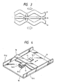
- Fig. 3 illustrates the principle of operation of the sheet feeding system as disclosed in the Japanese Patent Publication.
- the reference characters 11 and 12 in Fig. 3 denote a pair of elastic members in which travelling bending vibrations are produced as shown in the figure.
- a sheet 13 is sandwiched in the elastic members 11 and 12.
- a phase difference is set between the bending vibrations on the elastic members 11 and 12, whose phase difference is 180° spacially.
- the bending vibrations travel in such a manner that the convex portion, on the sheet side, of the bending of the elastic member 11 is always opposed to the convex portion, on the sheet side, of the bending of the elastic member 12.
- Fig. 4 is a perspective view of an example of the apparatus in which a sheet feeding force is produced in accordance with the principle described above.
- the reference characters 11 and 12 denote elastic members and 13 denotes a sheet to be fed.
- 14-1, 14-2, 15-1 (not shown) and 15-2 denote vibration members, 16 a pressing and supporting member, 17-1 and 17-2 side support plates and 18 a bottom plate.
- the elastic member 12 is supported on the bottom plate 18 and the elastic member 11 is supported by the pressing and supporting member 16.
- the member 16 possesses some elasticity with which the sheet 13 is pressed against the lower elastic member 12 through the upper elastic member 11. In this manner, the elastic members 11 and 12 hold the sheet sandwiched in between them. In the manner described above, the elastic members 11 and 12 are brought into bending vibration. At the time, the convex portion of bending of the elastic member 11 is substantially opposed to the convex portion of the bending of the elastic member 12. As a result of it, there is produced a sheet feeding which can move the sheet 13 in a direction indicated by the arrow in Fig. 4.
- the arrow is shown as a double arrow which means that the direction of sheet feeding is reversible by changing over the travelling direction of the vibration.
- the sheet feeding system as shown in Figs. 3 and 4 has, however, some problems to be solved.
- the vibration type of sheet feeder has generally a plurality of grooves and vibrating elements provided on the elastic members (vibration members) in order to lower the neutral plane of the thickness thereby achieving the desired effect of vibration.
- Thrust and speed obtainable for sheet feeding are not stable but variable depending upon the accuracy of alignment of two elastic members, especially alignment of the vibrating elements on one elastic member with the vibrating elements on the other elastic members. Because of it, the thrust and speed may be so dropped down that the desired efficiency of sheet feeding can not be obtained.
- Thrust and speed obtainable for sheet feeding are not stable but variable also depending upon the correspondence in phase of the travelling waves produced on two discrete elastic members. If the phase of the travelling wave produced on one elastic element does not correctly correspond to the phase of the travelling wave produced on the other elastic element, the thrust and feeding speed may be so dropped down that the desired efficiency of sheet feeding is no longer attainable.
- the primary object of the present invention is to solve the problems involved in the prior art apparatus as mentioned above, and to provide a sheet feeder with which the performance of sheet feeding can be improved.
- the object of the present invention is to provide a sheet feeder comprising a pair of elastic members having vibrating elements arranged on both of the elastic members and a sheet feeding means, which is characterized in that the vibrating elements on one of the elastic members and on the other elastic member are arranged so aligned with each other that the vibrating elements on the one elastic member are opposed to the vibrating elements on the other elastic member with a sheet being sandwiched in between them and that said sheet feeding means includes a travelling wave controlling means for controlling the phase relationship between the travelling wave produced in the one elastic member and the travelling wave produced in the other elastic member in such manner that the peak of the former travelling wave and the peak of the latter travelling wave coincide with each other.
- the sheet feeder comprises vibration members 1, 2, 3 and 4, elastic members 5 and 6, an oscillator 7 and a ⁇ /2 phase shifter. Designated by 9 is a sheet to be fed.
- Each of the vibration members is composed of a piezo-electric element.
- a cyclic voltage is applied to the vibration members 1 to 4 by the oscillator 7.
- the vibration members 1 and 2 are bonded to the elastic member 5 by means of adhesive or the like and the vibration members 3 and 4 are bonded to the elastic member 6.
- the elastic members 5 and 6 are conductive members connected to a grounding circuit.
- the vibration members 1 and 3 receive the cyclic voltage directly from the oscillator 7, whereas the vibration members 2 and 4 receives a ⁇ /2 phase-shifted cyclic voltage through the ⁇ /2 phase shifter. All of the cyclic voltages applied to the vibration members 1, 2, 3 and 4 have the same effective value.
- the vibration members 1, 2, 3 and 4 vibrate, which in turn brings the elastic members 5 and 6 into vibration.
- the vibration member 1 is spaced from the vibration member 2 by a distance of (n + 1/4) ⁇ wavelength where n is a natural number.
- the vibration member 3 is spaced from the vibration member 4 by the same distance.
- the elastic member 5 has a row of vibrating elements 5a projecting out in the direction perpendicular to the travelling direction of the travelling wave.
- the elastic member 6 has a row of vibrating elements 6a facing the row of the vibrating elements 5a on the elastic element 5.
- These vibrating elements serve to lower the neutral plane of the thickness of the elastic members thereby producing the desired vibration magnification effect.
- the sheet 9 comes into contact with the projected ends of the vibrating elements 5A, 6A arranged in face-to-face relation.
- the projected vibrating elements 5a and 6a on the elastic members 5 and 6 are arranged aligned with each other.
- the vibrations members 1 to 4 are arranged in such manner that the vibration members 1 and 2 on the elastic member 5 are symmetric to the vibration members 3 and 4 on the elastic member 6 relative to the plane of the sheet 9.
- the feeding force and feeding speed of the sheet do not decrease because the peaks of each travelling vibration wave correspond with each other, in other words, a peak point of a travelling wave does not fall into a bottom point of another travelling wave. Further, it should be noted that the peaks of each wave do not necessarily exactly correspond with each other and it would be allowed if there is a slight deviation between them.
- Fig. 2 shows a second embodiment of the invention.
- the vibration members 1 and 2 on the elastic element 5 are positionally not symmetric to the vibration members 3 and 4 relative to the plane of the sheet 9.
- the vibration members 3 and 4 are arranged in positions shifted from the positions of the vibration members 1 and 2.
- the phase of the cyclic voltage applied to the vibration members 1 and 2 can be shifted relative to that of cyclic voltage applied to the vibration members 3 and 4 by means of a phase shifter 10. Therefore, by suitably controlling the phase shift, man can adjust the travelling waves produced on the elastic members 5 and 6 in such manner that the peaks of the travelling waves coincide with each other.
- each vibration member (elastic member) pinching the sheet are respectively faced with each other, or the phase relation of the travelling vibration waves generated in the respective vibration member is controlled, in other words the wave length and speed of the respective vibration wave is controlled so as to correspond with each other, so that the peaks of each wave correspond with each other.
- the wave length and speed of the respective vibration wave is controlled so as to correspond with each other, so that the peaks of each wave correspond with each other.
- feeding apparatus comprising a first vibration means having projections provided with a predetermined distance therebetween, the first vibration means producing a first travelling vibration wave in response to an electrical signal applied thereto, and a second vibration means having projections located at the positions substantially corresponding to the projections of the first vibration means, the second vibration means producing a second travelling vibration wave proceeding in the same direction as the first travelling vibration wave in response to an electrical signal supplied thereto thereby the sheet inserted between the projections of the first vibration means and the projections of the second vibration means being fed by the first and second travelling vibration waves.
Landscapes
- Engineering & Computer Science (AREA)
- Mechanical Engineering (AREA)
- Physics & Mathematics (AREA)
- General Physics & Mathematics (AREA)
- General Electrical Machinery Utilizing Piezoelectricity, Electrostriction Or Magnetostriction (AREA)
- Feeding Of Articles By Means Other Than Belts Or Rollers (AREA)
- Sheets, Magazines, And Separation Thereof (AREA)
Abstract
Description
- The present invention relates to a sheet feeder useful for various apparatus provided with a mechanism for feeding a sheet such as computer, copier, printer, facsimile equipment, word processor, typewriter etc.
- In the conventional sheet feeding mechanism used in the above-mentioned apparatus, a rotating driving source such as a motor has been used to drive rubber rollers, belts or the like by which the feeding of sheet is effected.
- Another type of sheet feeding system known in the art is a vibration type of sheet feeding system as disclosed, for example, in Japanese Patent Application Laid-Open No. 59-177,243. In this sheet feeding system, a pair of elastic members are used to generate travelling vibration waves therein. The elastic members are in pressure-contact with a sheet to be fed and apply to the sheet a feeding force derived from the travelling waves produced in the elastic members.
- Fig. 3 illustrates the principle of operation of the sheet feeding system as disclosed in the Japanese Patent Publication. The
reference characters sheet 13 is sandwiched in theelastic members elastic members elastic member 11 is always opposed to the convex portion, on the sheet side, of the bending of theelastic member 12. If a certain point on the elastic member is particularly examined at the time, it will be shown that the point moves describing an elliptic locus as indicated by two arrows in Fig. 3. Regarding theelastic member 11, when the bending vibration on it travels rightwardly, the point moves clockwisely describing an elliptic locus as shown in Fig. 3. Consequently, the direction of the movement of the point on theelastic member 11 is opposite to the travelling direction of the vibration. The same is applicable to the movement of a point on the otherelastic member 12. From these movements of the points on both of theelastic members sheet 13. As indicated by an arrow, the direction of the sheet feeding is, therefore, opposite to the travelling direction of the bending vibration. - Fig. 4 is a perspective view of an example of the apparatus in which a sheet feeding force is produced in accordance with the principle described above.
- Again, the
reference characters - The
elastic member 12 is supported on thebottom plate 18 and theelastic member 11 is supported by the pressing and supportingmember 16. Themember 16 possesses some elasticity with which thesheet 13 is pressed against the lowerelastic member 12 through the upperelastic member 11. In this manner, theelastic members elastic members elastic member 11 is substantially opposed to the convex portion of the bending of theelastic member 12. As a result of it, there is produced a sheet feeding which can move thesheet 13 in a direction indicated by the arrow in Fig. 4. The arrow is shown as a double arrow which means that the direction of sheet feeding is reversible by changing over the travelling direction of the vibration. - The sheet feeding system as shown in Figs. 3 and 4 has, however, some problems to be solved.
- Although not shown in Figs. 3 and 4, the vibration type of sheet feeder according to the prior art has generally a plurality of grooves and vibrating elements provided on the elastic members (vibration members) in order to lower the neutral plane of the thickness thereby achieving the desired effect of vibration. When a sheet is held and moved between such elastic members provided with a plurality of grooves and vibrating elements, the following problems arise:
- (1) Thrust and speed obtainable for sheet feeding are not stable but variable depending upon the accuracy of alignment of two elastic members, especially alignment of the vibrating elements on one elastic member with the vibrating elements on the other elastic members. Because of it, the thrust and speed may be so dropped down that the desired efficiency of sheet feeding can not be obtained.
- (2) Thrust and speed obtainable for sheet feeding are not stable but variable also depending upon the correspondence in phase of the travelling waves produced on two discrete elastic members. If the phase of the travelling wave produced on one elastic element does not correctly correspond to the phase of the travelling wave produced on the other elastic element, the thrust and feeding speed may be so dropped down that the desired efficiency of sheet feeding is no longer attainable.
- Accordingly, the primary object of the present invention is to solve the problems involved in the prior art apparatus as mentioned above, and to provide a sheet feeder with which the performance of sheet feeding can be improved.
- More specifically, the object of the present invention is to provide a sheet feeder comprising a pair of elastic members having vibrating elements arranged on both of the elastic members and a sheet feeding means, which is characterized in that the vibrating elements on one of the elastic members and on the other elastic member are arranged so aligned with each other that the vibrating elements on the one elastic member are opposed to the vibrating elements on the other elastic member with a sheet being sandwiched in between them and that said sheet feeding means includes a travelling wave controlling means for controlling the phase relationship between the travelling wave produced in the one elastic member and the travelling wave produced in the other elastic member in such manner that the peak of the former travelling wave and the peak of the latter travelling wave coincide with each other.
- Other objects, features and advantages of the present invention will appear more clearly from the following description taken in connection with the accompanying drawings.
-
- Fig. 1 is a side view of an embodiment of the present invention;
- Fig. 2A is a side view of a second embodiment of the invention;
- Fig. 2B is a partial enlarged view of elastic member in the embodiment of Figs. 1 and 2A when the sheet is being fed.
- Fig. 3 is a schematic view illustrating the principle of the vibration type of sheet feeding system to which the present invention is pertinent; and
- Fig. 4 is a perspective view of an example of the prior art vibration type sheet feeder.
- Referring first Fig. 1 showing a first embodiment of the present inventions, the sheet feeder comprises
vibration members elastic members oscillator 7 and a π/2 phase shifter. Designated by 9 is a sheet to be fed. Each of the vibration members is composed of a piezo-electric element. A cyclic voltage is applied to thevibration members 1 to 4 by theoscillator 7. - As seen in Fig. 1, the
vibration members elastic member 5 by means of adhesive or the like and thevibration members elastic member 6. In this embodiment, theelastic members vibration members oscillator 7, whereas thevibration members vibration members - When the cyclic voltage is applied, the
vibration members elastic members vibration member 1 is spaced from thevibration member 2 by a distance of (n + 1/4) λ wavelength where n is a natural number. Also, thevibration member 3 is spaced from thevibration member 4 by the same distance. - As a result of the spaced arrangement of these vibration members, there is produced from the vibration a travelling wave on each of the
elastic members - Referring again to Fig. 1, the
elastic member 5 has a row of vibratingelements 5a projecting out in the direction perpendicular to the travelling direction of the travelling wave. Similarly, theelastic member 6 has a row of vibratingelements 6a facing the row of the vibratingelements 5a on theelastic element 5. These vibrating elements serve to lower the neutral plane of the thickness of the elastic members thereby producing the desired vibration magnification effect. The sheet 9 comes into contact with the projected ends of the vibrating elements 5A, 6A arranged in face-to-face relation. Thus, the projected vibratingelements elastic members - In this embodiment, the
vibrations members 1 to 4 are arranged in such manner that thevibration members elastic member 5 are symmetric to thevibration members elastic member 6 relative to the plane of the sheet 9. - With the above-described arrangement, the feeding force and feeding speed of the sheet do not decrease because the peaks of each travelling vibration wave correspond with each other, in other words, a peak point of a travelling wave does not fall into a bottom point of another travelling wave. Further, it should be noted that the peaks of each wave do not necessarily exactly correspond with each other and it would be allowed if there is a slight deviation between them.
- Fig. 2 shows a second embodiment of the invention.
- The same characters to Fig. 1 represent the same or corresponding members and elements.
- In the second embodiment, the
vibration members elastic element 5 are positionally not symmetric to thevibration members vibration members vibration members vibration members vibration members phase shifter 10. Therefore, by suitably controlling the phase shift, man can adjust the travelling waves produced on theelastic members - According to present invention, the projected ends of each vibration member (elastic member) pinching the sheet are respectively faced with each other, or the phase relation of the travelling vibration waves generated in the respective vibration member is controlled, in other words the wave length and speed of the respective vibration wave is controlled so as to correspond with each other, so that the peaks of each wave correspond with each other. Thus arrangement can improve the efficiency of sheet feeding magnificiently (cf.Fig. 2B).
- Disclosed is feeding apparatus comprising a first vibration means having projections provided with a predetermined distance therebetween, the first vibration means producing a first travelling vibration wave in response to an electrical signal applied thereto, and a second vibration means having projections located at the positions substantially corresponding to the projections of the first vibration means, the second vibration means producing a second travelling vibration wave proceeding in the same direction as the first travelling vibration wave in response to an electrical signal supplied thereto thereby the sheet inserted between the projections of the first vibration means and the projections of the second vibration means being fed by the first and second travelling vibration waves.
Claims (12)
said first vibration means is a loop-shaped member.
said second vibration means is a loop-shaped member.
said projections of said first vibration member is provided at a linear portion of said loop-shaped member.
said projections of said second vibration means is provided at a linear portion of said loop-shaped member.
the portion of the projections of said first vibration means engaging the sheet has a flat shape.
the portion of the projections of said second vibration means engaging the sheet has a flat shape.
said first vibration means is an elliptical shaped member.
said second vibration means is an elliptical shaped member.
(a) first vibration means having a projected contact portion, said first vibration means producing a first travelling vibration wave in response to an electrical signal supplied thereto;
(b) second vibration means having a contact portion provided at a portion across the sheet from said contact portion of said first vibration means, said second vibration means generating a second travelling vibration wave proceeding in the same direction as said first travelling vibration wave in response to an electric signal supplied thereto; and
(c) means for letting a peak of the first travelling vibration wave and a peak of the second travelling vibration wave correspond with each other whereby the sheet inserted between the contact portion of the first vibration means and the contact portion of the second vibration means is fed by the first and the second travelling vibration waves.
Applications Claiming Priority (2)
| Application Number | Priority Date | Filing Date | Title |
|---|---|---|---|
| JP31355/89 | 1989-02-10 | ||
| JP1031355A JP2687233B2 (en) | 1989-02-10 | 1989-02-10 | Sheet feeder |
Publications (3)
| Publication Number | Publication Date |
|---|---|
| EP0382253A2 true EP0382253A2 (en) | 1990-08-16 |
| EP0382253A3 EP0382253A3 (en) | 1990-10-24 |
| EP0382253B1 EP0382253B1 (en) | 1994-06-29 |
Family
ID=12328925
Family Applications (1)
| Application Number | Title | Priority Date | Filing Date |
|---|---|---|---|
| EP90102603A Expired - Lifetime EP0382253B1 (en) | 1989-02-10 | 1990-02-09 | Sheet Feeder |
Country Status (4)
| Country | Link |
|---|---|
| US (1) | US5176376A (en) |
| EP (1) | EP0382253B1 (en) |
| JP (1) | JP2687233B2 (en) |
| DE (1) | DE69010228T2 (en) |
Cited By (2)
| Publication number | Priority date | Publication date | Assignee | Title |
|---|---|---|---|---|
| EP0823330A3 (en) * | 1996-08-06 | 1999-06-09 | Seiko Instruments Inc. | Printer apparatus |
| EP2017905A3 (en) * | 2007-07-20 | 2012-07-11 | Canon Kabushiki Kaisha | Actuator |
Families Citing this family (8)
| Publication number | Priority date | Publication date | Assignee | Title |
|---|---|---|---|---|
| JP2563585B2 (en) * | 1989-06-22 | 1996-12-11 | キヤノン株式会社 | Transfer device |
| JPH05116788A (en) * | 1991-10-29 | 1993-05-14 | Canon Inc | Paper sheet feeding device |
| JPH05254110A (en) * | 1992-03-10 | 1993-10-05 | Canon Inc | Printer |
| JP3162486B2 (en) * | 1992-06-25 | 2001-04-25 | キヤノン株式会社 | Printer device |
| JPH06178560A (en) * | 1992-12-03 | 1994-06-24 | Canon Inc | Vibration wave motor and printer |
| JPH08280185A (en) * | 1995-04-07 | 1996-10-22 | Nikon Corp | Ultrasonic actuator |
| US6068256A (en) * | 1999-07-28 | 2000-05-30 | Technology Commercialization Corp. | Piezoelectric conveying device |
| JP2013029769A (en) | 2011-07-29 | 2013-02-07 | Canon Inc | Image forming device |
Family Cites Families (21)
| Publication number | Priority date | Publication date | Assignee | Title |
|---|---|---|---|---|
| US3744789A (en) * | 1971-05-13 | 1973-07-10 | Addressograph Multigraph | Sheet feeder assembly |
| US3747921A (en) * | 1971-12-28 | 1973-07-24 | Ibm | Document feed device |
| SU818989A1 (en) * | 1979-03-11 | 1981-04-07 | Каунасский Политехнический Институтим. Ahtahaca Снечкуса | Jigging conveyer |
| DD208461A3 (en) * | 1982-08-19 | 1984-05-02 | Klaus Tilger | ARRANGEMENT FOR THE TRANSPORT AND ALLOCATION OF SHEET-MONEY OBJECTS |
| JPS59177243A (en) * | 1983-03-23 | 1984-10-06 | Canon Inc | Sheet feed device |
| JPS612636A (en) * | 1984-06-15 | 1986-01-08 | Ricoh Co Ltd | Sheet transfer device |
| JPS6155012A (en) * | 1984-08-24 | 1986-03-19 | Canon Inc | Method and apparatus for transfer by vibrating wave |
| JPS6186333A (en) * | 1984-10-05 | 1986-05-01 | Canon Inc | paper feeder |
| JPS61124412A (en) * | 1984-11-16 | 1986-06-12 | Tdk Corp | Conveying device |
| JPS61154487A (en) * | 1984-12-26 | 1986-07-14 | Canon Inc | linear vibration wave motor |
| US4752711A (en) * | 1985-03-29 | 1988-06-21 | Canon Kabushiki Kaisha | Vibration wave motor |
| JPS61224882A (en) * | 1985-03-29 | 1986-10-06 | Canon Inc | vibration wave motor |
| JPS61224881A (en) * | 1985-03-29 | 1986-10-06 | Canon Inc | vibration wave motor |
| US4692652A (en) * | 1985-03-29 | 1987-09-08 | Canon Kabushiki Kaisha | Vibration wave motor |
| JPS6429784A (en) * | 1987-07-24 | 1989-01-31 | Fujitsu Ltd | Testing method for defect of magnetic disk medium |
| JPS6460532A (en) * | 1987-08-31 | 1989-03-07 | Nec Corp | Paper feed mechanism |
| JP2690907B2 (en) * | 1987-09-25 | 1997-12-17 | 株式会社日立製作所 | Composite piezoelectric motor |
| DE3880781T2 (en) * | 1987-10-23 | 1993-10-21 | Hitachi Ltd | Method and device for conveying an object by means of vibration. |
| EP0336627B1 (en) * | 1988-03-31 | 1994-08-03 | Dunlop Limited | Resilient mounting |
| US5062622A (en) * | 1989-01-19 | 1991-11-05 | Canon Kabushiki Kaisha | Vibratory sheet feeder which uses phase adjustment to control the sheet feeding speed |
| JP2705820B2 (en) * | 1989-02-28 | 1998-01-28 | キヤノン株式会社 | Vibration wave motor device |
-
1989
- 1989-02-10 JP JP1031355A patent/JP2687233B2/en not_active Expired - Fee Related
-
1990
- 1990-02-09 DE DE69010228T patent/DE69010228T2/en not_active Expired - Fee Related
- 1990-02-09 EP EP90102603A patent/EP0382253B1/en not_active Expired - Lifetime
-
1991
- 1991-08-29 US US07/752,965 patent/US5176376A/en not_active Expired - Lifetime
Cited By (2)
| Publication number | Priority date | Publication date | Assignee | Title |
|---|---|---|---|---|
| EP0823330A3 (en) * | 1996-08-06 | 1999-06-09 | Seiko Instruments Inc. | Printer apparatus |
| EP2017905A3 (en) * | 2007-07-20 | 2012-07-11 | Canon Kabushiki Kaisha | Actuator |
Also Published As
| Publication number | Publication date |
|---|---|
| DE69010228D1 (en) | 1994-08-04 |
| DE69010228T2 (en) | 1994-10-27 |
| EP0382253A3 (en) | 1990-10-24 |
| JPH02209341A (en) | 1990-08-20 |
| EP0382253B1 (en) | 1994-06-29 |
| JP2687233B2 (en) | 1997-12-08 |
| US5176376A (en) | 1993-01-05 |
Similar Documents
| Publication | Publication Date | Title |
|---|---|---|
| EP0880185B1 (en) | Ultrasonic motor and ultrasonic apparatus with ultrasonic motor | |
| US5132582A (en) | Recording medium transferring apparatus and vibrating element used therein | |
| US5233258A (en) | Ultrasonic sheet feeder, low-profile ultrasonic motor, and method of driving the same | |
| US5130599A (en) | Vibrator-type actuator | |
| US5176376A (en) | Vibration sheet feeder | |
| JPH0389875A (en) | Linear ultrasonic motor | |
| EP0691692B1 (en) | Vibration driven motor | |
| EP0435496A1 (en) | A vibration driven motor and thermal jet type printer using the same | |
| EP0475752B1 (en) | Vibration-driven motor | |
| US5416374A (en) | Ultrasonic motor and electronic apparatus equipped with ultrasonic motor | |
| EP0405497B1 (en) | Sheet feeding device | |
| US5274294A (en) | Vibration wave driven motor | |
| US4810923A (en) | Vibration wave motor | |
| EP0437050B1 (en) | Vibration wave driven apparatus | |
| US6072266A (en) | Vibration actuator | |
| EP0436336B1 (en) | Vibration wave driven apparatus | |
| EP0404158B1 (en) | Sheet feeding apparatus | |
| EP0385409A2 (en) | Sheet feeding device | |
| US5094444A (en) | Sheet feeding device | |
| EP0404113B1 (en) | Sheet feeding apparatus | |
| JPH04281A (en) | Micro-slide device | |
| JPH01177881A (en) | Vibrator for ultrasonic motor | |
| JPH0342443A (en) | sheet feeding device | |
| JPH02276720A (en) | Transport device | |
| JPH0331138A (en) | sheet feeding device |
Legal Events
| Date | Code | Title | Description |
|---|---|---|---|
| PUAI | Public reference made under article 153(3) epc to a published international application that has entered the european phase |
Free format text: ORIGINAL CODE: 0009012 |
|
| AK | Designated contracting states |
Kind code of ref document: A2 Designated state(s): DE FR GB IT |
|
| PUAL | Search report despatched |
Free format text: ORIGINAL CODE: 0009013 |
|
| AK | Designated contracting states |
Kind code of ref document: A3 Designated state(s): DE FR GB IT |
|
| RHK1 | Main classification (correction) |
Ipc: B65H 5/16 |
|
| 17P | Request for examination filed |
Effective date: 19901221 |
|
| 17Q | First examination report despatched |
Effective date: 19920818 |
|
| GRAA | (expected) grant |
Free format text: ORIGINAL CODE: 0009210 |
|
| AK | Designated contracting states |
Kind code of ref document: B1 Designated state(s): DE FR GB IT |
|
| REF | Corresponds to: |
Ref document number: 69010228 Country of ref document: DE Date of ref document: 19940804 |
|
| ITF | It: translation for a ep patent filed | ||
| ET | Fr: translation filed | ||
| ITTA | It: last paid annual fee | ||
| PLBE | No opposition filed within time limit |
Free format text: ORIGINAL CODE: 0009261 |
|
| STAA | Information on the status of an ep patent application or granted ep patent |
Free format text: STATUS: NO OPPOSITION FILED WITHIN TIME LIMIT |
|
| 26N | No opposition filed | ||
| REG | Reference to a national code |
Ref country code: GB Ref legal event code: IF02 |
|
| PGFP | Annual fee paid to national office [announced via postgrant information from national office to epo] |
Ref country code: DE Payment date: 20050203 Year of fee payment: 16 |
|
| PGFP | Annual fee paid to national office [announced via postgrant information from national office to epo] |
Ref country code: FR Payment date: 20050208 Year of fee payment: 16 |
|
| PGFP | Annual fee paid to national office [announced via postgrant information from national office to epo] |
Ref country code: GB Payment date: 20050209 Year of fee payment: 16 |
|
| PG25 | Lapsed in a contracting state [announced via postgrant information from national office to epo] |
Ref country code: GB Free format text: LAPSE BECAUSE OF NON-PAYMENT OF DUE FEES Effective date: 20060209 |
|
| PGFP | Annual fee paid to national office [announced via postgrant information from national office to epo] |
Ref country code: IT Payment date: 20060228 Year of fee payment: 17 |
|
| PG25 | Lapsed in a contracting state [announced via postgrant information from national office to epo] |
Ref country code: DE Free format text: LAPSE BECAUSE OF NON-PAYMENT OF DUE FEES Effective date: 20060901 |
|
| GBPC | Gb: european patent ceased through non-payment of renewal fee |
Effective date: 20060209 |
|
| REG | Reference to a national code |
Ref country code: FR Ref legal event code: ST Effective date: 20061031 |
|
| PG25 | Lapsed in a contracting state [announced via postgrant information from national office to epo] |
Ref country code: FR Free format text: LAPSE BECAUSE OF NON-PAYMENT OF DUE FEES Effective date: 20060228 |
|
| PG25 | Lapsed in a contracting state [announced via postgrant information from national office to epo] |
Ref country code: IT Free format text: LAPSE BECAUSE OF NON-PAYMENT OF DUE FEES Effective date: 20070209 |