EP0382002B1 - Friction core holder - Google Patents
Friction core holder Download PDFInfo
- Publication number
- EP0382002B1 EP0382002B1 EP90101420A EP90101420A EP0382002B1 EP 0382002 B1 EP0382002 B1 EP 0382002B1 EP 90101420 A EP90101420 A EP 90101420A EP 90101420 A EP90101420 A EP 90101420A EP 0382002 B1 EP0382002 B1 EP 0382002B1
- Authority
- EP
- European Patent Office
- Prior art keywords
- segments
- mandrel
- segment
- core
- center
- Prior art date
- Legal status (The legal status is an assumption and is not a legal conclusion. Google has not performed a legal analysis and makes no representation as to the accuracy of the status listed.)
- Expired - Lifetime
Links
- 239000000463 material Substances 0.000 claims description 13
- 239000004033 plastic Substances 0.000 claims description 6
- 229920003023 plastic Polymers 0.000 claims description 6
- 239000002023 wood Substances 0.000 claims description 5
- 229910000831 Steel Inorganic materials 0.000 claims description 3
- 239000002184 metal Substances 0.000 claims description 3
- 239000012858 resilient material Substances 0.000 claims description 3
- 239000010959 steel Substances 0.000 claims description 3
- 230000013011 mating Effects 0.000 claims description 2
- 239000011162 core material Substances 0.000 description 66
- 239000003292 glue Substances 0.000 description 21
- 238000004804 winding Methods 0.000 description 7
- 238000005520 cutting process Methods 0.000 description 6
- 238000004519 manufacturing process Methods 0.000 description 4
- 239000000853 adhesive Substances 0.000 description 3
- 230000001070 adhesive effect Effects 0.000 description 3
- 239000004753 textile Substances 0.000 description 3
- 239000000123 paper Substances 0.000 description 2
- 239000007921 spray Substances 0.000 description 2
- 229920001875 Ebonite Polymers 0.000 description 1
- 241000030366 Scorpidinae Species 0.000 description 1
- 238000009825 accumulation Methods 0.000 description 1
- 229910045601 alloy Inorganic materials 0.000 description 1
- 239000000956 alloy Substances 0.000 description 1
- 238000013459 approach Methods 0.000 description 1
- 239000011094 fiberboard Substances 0.000 description 1
- 239000002657 fibrous material Substances 0.000 description 1
- 238000009434 installation Methods 0.000 description 1
- 238000005304 joining Methods 0.000 description 1
- 229910001092 metal group alloy Inorganic materials 0.000 description 1
- 238000000034 method Methods 0.000 description 1
- 229920000915 polyvinyl chloride Polymers 0.000 description 1
- 239000004800 polyvinyl chloride Substances 0.000 description 1
- -1 printing Substances 0.000 description 1
- 239000010935 stainless steel Substances 0.000 description 1
- 229910001220 stainless steel Inorganic materials 0.000 description 1
- 125000000391 vinyl group Chemical group [H]C([*])=C([H])[H] 0.000 description 1
- 229920002554 vinyl polymer Polymers 0.000 description 1
Images


Classifications
-
- B—PERFORMING OPERATIONS; TRANSPORTING
- B65—CONVEYING; PACKING; STORING; HANDLING THIN OR FILAMENTARY MATERIAL
- B65H—HANDLING THIN OR FILAMENTARY MATERIAL, e.g. SHEETS, WEBS, CABLES
- B65H19/00—Changing the web roll
- B65H19/22—Changing the web roll in winding mechanisms or in connection with winding operations
- B65H19/2207—Changing the web roll in winding mechanisms or in connection with winding operations the web roll being driven by a winding mechanism of the centre or core drive type
- B65H19/2223—Turret-type with more than two roll supports
-
- B—PERFORMING OPERATIONS; TRANSPORTING
- B65—CONVEYING; PACKING; STORING; HANDLING THIN OR FILAMENTARY MATERIAL
- B65H—HANDLING THIN OR FILAMENTARY MATERIAL, e.g. SHEETS, WEBS, CABLES
- B65H19/00—Changing the web roll
- B65H19/22—Changing the web roll in winding mechanisms or in connection with winding operations
- B65H19/2276—The web roll being driven by a winding mechanism of the coreless type
-
- B—PERFORMING OPERATIONS; TRANSPORTING
- B65—CONVEYING; PACKING; STORING; HANDLING THIN OR FILAMENTARY MATERIAL
- B65H—HANDLING THIN OR FILAMENTARY MATERIAL, e.g. SHEETS, WEBS, CABLES
- B65H75/00—Storing webs, tapes, or filamentary material, e.g. on reels
- B65H75/02—Cores, formers, supports, or holders for coiled, wound, or folded material, e.g. reels, spindles, bobbins, cop tubes, cans, mandrels or chucks
- B65H75/18—Constructional details
- B65H75/24—Constructional details adjustable in configuration, e.g. expansible
- B65H75/242—Expansible spindles, mandrels or chucks, e.g. for securing or releasing cores, holders or packages
- B65H75/246—Expansible spindles, mandrels or chucks, e.g. for securing or releasing cores, holders or packages expansion caused by relative rotation around the supporting spindle or core axis
-
- B—PERFORMING OPERATIONS; TRANSPORTING
- B65—CONVEYING; PACKING; STORING; HANDLING THIN OR FILAMENTARY MATERIAL
- B65H—HANDLING THIN OR FILAMENTARY MATERIAL, e.g. SHEETS, WEBS, CABLES
- B65H2408/00—Specific machines
- B65H2408/20—Specific machines for handling web(s)
- B65H2408/23—Winding machines
- B65H2408/231—Turret winders
- B65H2408/2315—Turret winders specified by number of arms
- B65H2408/23157—Turret winders specified by number of arms with more than three arms
-
- Y—GENERAL TAGGING OF NEW TECHNOLOGICAL DEVELOPMENTS; GENERAL TAGGING OF CROSS-SECTIONAL TECHNOLOGIES SPANNING OVER SEVERAL SECTIONS OF THE IPC; TECHNICAL SUBJECTS COVERED BY FORMER USPC CROSS-REFERENCE ART COLLECTIONS [XRACs] AND DIGESTS
- Y10—TECHNICAL SUBJECTS COVERED BY FORMER USPC
- Y10T—TECHNICAL SUBJECTS COVERED BY FORMER US CLASSIFICATION
- Y10T279/00—Chucks or sockets
- Y10T279/10—Expanding
- Y10T279/1074—Rotary actuator
- Y10T279/1079—Clutch or self-actuating type
Definitions
- the present invention relates to a device for winding reels of material onto a core. More particularly, the present invention relates to an core holder assembly for tightly gripping and holding a resilient core on a mandrel for the winding of defined lengths of webs onto such core.
- the invention is particularly useful in the manufacture of labels in the printing industry, and is readily adaptable to the textile and other industries which wind sheets of material onto a core while the core is situated on a mandrel, then remove the filled core and replace it with an empty core.
- Kupper U.S. patent 4,651,865 entitled Device for Unloading a Coil, shows mandrels and coils for textile threads, the coils being rotated by end contact to drive means.
- Rohde U. S. Patent 4,390,138 entitled Reeling Apparatus for a Web, shows presently used core tubes on a modern winding shaft, which has no provision for tightly holding the core tube to the shaft.
- Patent 3,930,620 entitled Turret Rewinder, which teaches a core C on an apparently round spindle, and fails to suggest any means for causing both the spindle and the core to rotate at the same angular velocity; Nichols U. S. Patent 1,484,842, entitled Slitting and Rewinding Machine; and Mulfarth U. S. Patent 4,630,783, entitled Machine for Winding a Web of Paper on a Roll.
- a large disc 10 is mounted for rotation on a base 12, about axis 13.
- the disc 10 is provided with 8 label friction mandrels or spindles 14, all of which protrude from one side of disc 10 and are driven from the other side.
- the core is held onto the mandrel 14 by, segments 86, which have slightly offset respective centers.
- Mandrels are preferably made from steel, however, they can be made of any metal or alloy, wood, hard rubber, hard plastic, or the like.
- the reverse side of the turret rewind base 12 carries drive means, including a motor driven sheave 36, and a drive sheave arrangement in which drive belt 38 engages only two or three of the mandrel drive sheaves 40 at any one time (See Figure 2).
- Idler pulleys 42 are provided to create proper tension in belt 38 and the proper drive angle of belt 38 with regard to each sheave 40 in a driven position.
- a glue unit 44 includes a glue-containing receptacle or trough 46, a roller-applicator 48 mounted at the trough so that a portion of the roller extends into the glue contained in the trough, and means for moving the glue unit laterally into and out of engagement with a core on a spindle.
- the glue unit is mounted on a track 50 which is connected to the frame 12, and is preferably reciprocally powered along the track by a pneumatic cylinder, not shown.
- the glue unit may advantageously carry a lower glue carrier roll 52 which is partially submerged in the glue pool and contacts the roller-applicator 48 by which the carrier roll applies glue to the applicator roll 48, which allows the applicator roll to be of a smaller diameter than otherwise would be required to extend into the glue pool in the trough.
- a carrier roll will prevent excessive glue from being applied to the carrier roll and thus to the core.
- a web cutting assembly 56 including a cutting blade 58, is mounted for horizontal movement on a track 60, which is fixed to frame 12.
- a solenoid-actuated pneumatic cylinder 62 is connected to the blade assembly for horizontal movement along the track 60.
- Another solenoid-actuated pneumatic cylinder controls vertical movement of the blade.
- the cutting assembly includes a web guide roll 66, which is an idler roll that controls the angle and path of the web as it is being cut, as well as preventing the moving web from contacting the knife blade 58 and causing a "cobble", or mishap. If desired, the blade 58 can be set to cut at an angle of up to 45 degrees from the vertical.
- Contact roller 68 pushes the web against the glued core momentarily, simultaneously with retraction of the knife blade 58.
- a counter may be provided to accurately count the number of labels on the core, whereupon when a predetermined number is reached it would generate a signal to activate movement of the cutting assembly and blade, then to index the mandrel to the next position by rotation of the disc plate to its new orientation, and activate the glue unit to apply adhesive to a newly positioned core in the standby position.
- a detector comprising a photoelectric cell 70, is focused at a location indicated by reflector 72, and is so adjusted that its beam is aimed to just miss a mandrel if it carries no core thereon, but the beam will be interrupted by a filled core or roll.
- the detector is provided with an audible alarm which also controls an emergency stop for preventing further indexing of the turret apparatus until the label or web-containing roll can be removed from the mandrel at the focused position indicated at 75.
- a safety guard 8A may be provided to prevent contact of any person with the cutting blade.
- the preferred core holder embodiment is shown in Figures 7 through 10.
- the center C1 of the outer arc having radius R1 is not coincident with center C2 of the bore having radius R2.
- the center C2 of the bore is offset from center C1 from(0.015 to 0.35 inches) about 0.4 to about 9mm , as shown in Figure 11, but preferably from(0.025 to 0.055 inches) about 0.63 to about 1.4 mm.
- segments 102 are assembled with connectors, preferably resilient connectors such as O-Rings 104 in grooves 106 as shown in Figures 9 and 10 to form a core holder.
- connectors preferably resilient connectors such as O-Rings 104 in grooves 106 as shown in Figures 9 and 10 to form a core holder.
- the segments When the segments are assembled, they provide a non-round hole for accomodating the mandrel, with stops preventing more than a quarter turn of the core holder about the mandrel.
- a core 18 is placed on a mandrel 14, prior to the mandrel being indexed to the location for web accumulation.
- the mandrel begins turning, as its associated drive sheave 40 is engaged by drive belt 38.
- the glue unit is activated to move horizontally until the applicator roll 48 touches a core for one core revolution, the applicator applying glue for one revolution, the exact time of the glue application being computer controlled.
- the glue unit retracts.
- the cutting unit moves forward to slice the label-containing web, the turret indexes, and the glue unit applies adhesive to the next core.
- the action of the blade dropping and slicing the web actually forces the web down against the adhesive-bearing core, and immediately upon blade retraction, the core is already accumulating labels. Then the turret 10 indexes to the next station, meaning that the plate disc has revolved 1/8 of a revolution.
- the label-filled core 18 is removed after the turret has indexed twice, so that the associated drive sheave for the mandrel which that core is gripping is no longer engaged by drive belt 38, and the mandrel is no longer turning.
- the empty core is turning prior to the glue being applied, and the core is also turning while it is filling. Then when it indexes to the next station, it can be removed.
- each mandrel accomodate the core support segments when offset to the non-circular central orifice orientation.
- spindle 14 When the spindle 14 turns in an operative direction, it force, the split center of the core-gripping segments to assume a round configuration, rather than that of two slightly off-set half-moons. Reverse pressure on the core will release the outward force from the mandrel and allow the core to be readily removed therefrom.
- a rewind machine is used to rewind the large rolls into small, easily handled rolls for a label applicator, such as a portable label applicator.
- a label applicator such as a portable label applicator.
- each mandrel 84 which has longitudinal flat faces, has a square cross-section.
- a core is held onto the mandrel 84 by four quad-circular disc-like segments 86, which have slightly offset respective center openings 88 to accomodate the mandrel.
- Each segment 86 is identical. As shown, four such segments form a completed core holder, when assembled.
- the core holder is turned about the mandrel 84, one edge of each segment 86 is forced outwardly, as shown in Figures 7 and 8, tightening against the inner surface of the core 18.
- the segments of the core holder return to the positions shown in Figures 6 and 9, releasing their grip on the core.
- the mandrel is constructed of harder material than the segments. Wear of the mandrel or spindle is minimal when the spindle is hard or hardened material such as steel, and the segments are readily replaceable softer materials such as wood, plastic, fibrous material, or other similar materials.
- the core material may be a hard wear resistant material, much as wood, hard plastic, metal, metal alloy, even stainless steel, and the invention is still readily operable.
- the segments may be held together as shown in Figure 3 by O-rings 90 in annular grooves 92. Alternatively, they may be connected loosely by any convenient connecting means that avoids interference with the operation of the segments, such as O-Rings 96 on pins 98 extending from the end faces of each segment 86, as shown in Figures 14 and 15; wire connectors such as wire 110 having end loops for attaching to pins 112 on adjacent segments; rubber or resilient connectors 116 between fasteners 118 on adjacent segments, or other suitable connecting devices which will loosely maintain the segments in the proper juxtaposition.
- any convenient connecting means that avoids interference with the operation of the segments, such as O-Rings 96 on pins 98 extending from the end faces of each segment 86, as shown in Figures 14 and 15; wire connectors such as wire 110 having end loops for attaching to pins 112 on adjacent segments; rubber or resilient connectors 116 between fasteners 118 on adjacent segments, or other suitable connecting devices which will loosely maintain the segments in the proper juxtaposition.
- FIG. 13 Also shown in Figure 13 is an alternative connecting means which comprises a slot 120 in each end face of each segment mating with an adjacent slot in the opposed segment and having an expanded recess 122 therein, and a double headed connector 124 with a shank between the heads engaged within said expanded recess to hold the segments loosely together.
- the mandrel preferably has a regular polygonal cross section, such as an equilateral triangle, square, hexagon, etc.
- the core holder assembly has the same number of segments as the polygon has sides, and the centers of the outer and inner arcs at each segment are offset the same amounts as stated previously.
- An alternative glue applicator unit includes a pressure spray dispenser directed to the core position at the glue applicator station, with associated glue supply.
- the spray dispensing heads can be mounted for horizontal movement toward and away from the active position, and each head is capable of being shut off without clogging by rotation to a standby position opening upwardly.
Landscapes
- Replacement Of Web Rolls (AREA)
- Winding Of Webs (AREA)
- Storage Of Web-Like Or Filamentary Materials (AREA)
Description
- The present invention relates to a device for winding reels of material onto a core. More particularly, the present invention relates to an core holder assembly for tightly gripping and holding a resilient core on a mandrel for the winding of defined lengths of webs onto such core. The invention is particularly useful in the manufacture of labels in the printing industry, and is readily adaptable to the textile and other industries which wind sheets of material onto a core while the core is situated on a mandrel, then remove the filled core and replace it with an empty core.
- In the manufacturing of labels, after printing, it is necessary to rewind reels of label-carrying webs bearing large quantities of labels onto smaller rolls of accurate and defined quantities of labels. In actual manufacture, it requires about twice as much time and accompanying manpower to rewind the labels as to accomplish the original manufacture or printing of the labels.
- The following patents are believed to be exemplary of the prior art with regard to the subject invention:
Kupper U.S. patent 4,651,865, entitled Device for Unloading a Coil, shows mandrels and coils for textile threads, the coils being rotated by end contact to drive means. - Rohde U. S. Patent 4,390,138, entitled Reeling Apparatus for a Web, shows presently used core tubes on a modern winding shaft, which has no provision for tightly holding the core tube to the shaft.
- Most patents covering winders and rewwinders fail to show details of core holders. Such patents are exemplified by:
Marshall U. S. Patent 4,518,126, entitled Take-Up Mechanism, which shows a winding takeup mechanism for controlling webs on tubes;
Cooper U. S. Patent 4,416,426, entitled Web Treatment Apparatus, which shows four mandrels which index to various positions;
Clements U. S. Patent 4,526,638, entitled Apparatus and Method for Joining Webs, which shows an expandable drivable support for reel core ends, which are only laterally expandable for reels of different widths;
Taitel U. S. Patent 3,930,620, entitled Turret Rewinder, which teaches a core C on an apparently round spindle, and fails to suggest any means for causing both the spindle and the core to rotate at the same angular velocity;
Nichols U. S. Patent 1,484,842, entitled Slitting and Rewinding Machine; and
Mulfarth U. S. Patent 4,630,783, entitled Machine for Winding a Web of Paper on a Roll. - It is the primary object of this invention to provide means of holding a core tightly on a mandrel for winding of a web onto the core.
- It is also an object of this invention to provide a means of easy removal of a core from a mandrel.
- It is also an object of this invention to provide apparatus for winding webs or material which is equally adaptable to the paper, printing, and textile industries.
- These objects are achieved by an apparatus in accordance with claim 1.
- The foregoing and other objects will become more readily apparent from the following detailed description and the appended drawings, in which:
- Figure 1 is a front view of a label auto-transfer turret rewind assembly on which the invented core holder is advantageously used.
- Figure 2 is a rear view of the label turret rewind assembly of Figure 1.
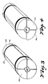
- Figure 3 is an isometric view of an alternative friction core holder in the deactivated position.
- Figure 4 is an end view of the friction core holder of Figure 3 in the activated position.
- Figure 5 is an end view of another alternative friction core holder in the activated position.
- Figure 6 is an end view of the friction core holder of Figure 5 in the activated position.
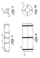
- Figure 7 is a side view of a single segment of a 4-segment core holder.
- Figure 8 is an end view of the segment of Figure 7.
- Figure 9 is a side view or an assembled 4-segment core holder using the segments of Figure 7.
- Figure 10 is an and view of the assembled core holder of Figure 9.
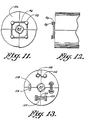
- Figure 11 is an end view of a 4-segment friction core holder showing an alternative segment connecting means.
- Figure 12 is a partially cutaway side view of the friction core holder of Figure 11.
- Figure 13 is an end view of another 4-segment friction core holder showing several alternative connector devices.
- Referring now to Figure 1, which depicts the invention in use in the lable printing industry, a
large disc 10 is mounted for rotation on abase 12, aboutaxis 13. Thedisc 10 is provided with 8 label friction mandrels orspindles 14, all of which protrude from one side ofdisc 10 and are driven from the other side. - Each
mandrel 14, which has a longitudinal flat or planar face 16, holds acore 18, which is generally made of cardboard, fiberboard, vinyl, plastic, or other resilient material. The core is held onto themandrel 14 by,segments 86, which have slightly offset respective centers. Mandrels are preferably made from steel, however, they can be made of any metal or alloy, wood, hard rubber, hard plastic, or the like. - The reverse side of the
turret rewind base 12 carries drive means, including a motor drivensheave 36, and a drive sheave arrangement in whichdrive belt 38 engages only two or three of themandrel drive sheaves 40 at any one time (See Figure 2). Idlerpulleys 42 are provided to create proper tension inbelt 38 and the proper drive angle ofbelt 38 with regard to eachsheave 40 in a driven position. - A
glue unit 44 includes a glue-containing receptacle ortrough 46, a roller-applicator 48 mounted at the trough so that a portion of the roller extends into the glue contained in the trough, and means for moving the glue unit laterally into and out of engagement with a core on a spindle. The glue unit is mounted on atrack 50 which is connected to theframe 12, and is preferably reciprocally powered along the track by a pneumatic cylinder, not shown. The glue unit may advantageously carry a lowerglue carrier roll 52 which is partially submerged in the glue pool and contacts the roller-applicator 48 by which the carrier roll applies glue to theapplicator roll 48, which allows the applicator roll to be of a smaller diameter than otherwise would be required to extend into the glue pool in the trough. In addition, the use of a carrier roll will prevent excessive glue from being applied to the carrier roll and thus to the core. - A
web cutting assembly 56, including acutting blade 58, is mounted for horizontal movement on a track 60, which is fixed toframe 12. A solenoid-actuatedpneumatic cylinder 62 is connected to the blade assembly for horizontal movement along the track 60. Another solenoid-actuated pneumatic cylinder controls vertical movement of the blade. The cutting assembly includes aweb guide roll 66, which is an idler roll that controls the angle and path of the web as it is being cut, as well as preventing the moving web from contacting theknife blade 58 and causing a "cobble", or mishap. If desired, theblade 58 can be set to cut at an angle of up to 45 degrees from the vertical. Contactroller 68 pushes the web against the glued core momentarily, simultaneously with retraction of theknife blade 58. - The indexing of each core-containing mandrel to the next position is automatically controlled. A counter may be provided to accurately count the number of labels on the core, whereupon when a predetermined number is reached it would generate a signal to activate movement of the cutting assembly and blade, then to index the mandrel to the next position by rotation of the disc plate to its new orientation, and activate the glue unit to apply adhesive to a newly positioned core in the standby position.
- A detector, comprising a
photoelectric cell 70, is focused at a location indicated by reflector 72, and is so adjusted that its beam is aimed to just miss a mandrel if it carries no core thereon, but the beam will be interrupted by a filled core or roll. The detector is provided with an audible alarm which also controls an emergency stop for preventing further indexing of the turret apparatus until the label or web-containing roll can be removed from the mandrel at the focused position indicated at 75. - A safety guard 8A may be provided to prevent contact of any person with the cutting blade.
- The preferred core holder embodiment is shown in Figures 7 through 10. The center C₁ of the outer arc having radius R₁ is not coincident with center C₂ of the bore having radius R₂. The center C₂ of the bore is offset from center C₁ from(0.015 to 0.35 inches) about 0.4 to about 9mm , as shown in Figure 11, but preferably from(0.025 to 0.055 inches) about 0.63 to about 1.4 mm.
- Four
identical segments 102, as shown in Figures 7 and 8 are assembled with connectors, preferably resilient connectors such as O-Rings 104 ingrooves 106 as shown in Figures 9 and 10 to form a core holder. When the segments are assembled, they provide a non-round hole for accomodating the mandrel, with stops preventing more than a quarter turn of the core holder about the mandrel. - In operation, a
core 18 is placed on amandrel 14, prior to the mandrel being indexed to the location for web accumulation. As it approacheslocation 18A, the mandrel begins turning, as its associateddrive sheave 40 is engaged bydrive belt 38. Upon reaching the core location indicated at 18A, the glue unit is activated to move horizontally until theapplicator roll 48 touches a core for one core revolution, the applicator applying glue for one revolution, the exact time of the glue application being computer controlled. The glue unit retracts. When the active core is filled, the cutting unit moves forward to slice the label-containing web, the turret indexes, and the glue unit applies adhesive to the next core. - The action of the blade dropping and slicing the web actually forces the web down against the adhesive-bearing core, and immediately upon blade retraction, the core is already accumulating labels. Then the
turret 10 indexes to the next station, meaning that the plate disc has revolved 1/8 of a revolution. The label-filledcore 18 is removed after the turret has indexed twice, so that the associated drive sheave for the mandrel which that core is gripping is no longer engaged bydrive belt 38, and the mandrel is no longer turning. The empty core is turning prior to the glue being applied, and the core is also turning while it is filling. Then when it indexes to the next station, it can be removed. - The elongated flat sides of each mandrel accomodate the core support segments when offset to the non-circular central orifice orientation. When the
spindle 14 turns in an operative direction, it force, the split center of the core-gripping segments to assume a round configuration, rather than that of two slightly off-set half-moons. Reverse pressure on the core will release the outward force from the mandrel and allow the core to be readily removed therefrom. - A rewind machine is used to rewind the large rolls into small, easily handled rolls for a label applicator, such as a portable label applicator. Use of the subject invention allows the quicker installation of cores and romoval of filled rolls, with an attendant reduction of required personnel time for these operations.
- In the embodiment of Figures 3 and 4, each
mandrel 84, which has longitudinal flat faces, has a square cross-section. A core is held onto themandrel 84 by four quad-circular disc-like segments 86, which have slightly offset respective center openings 88 to accomodate the mandrel. Eachsegment 86 is identical. As shown, four such segments form a completed core holder, when assembled. When the core holder is turned about themandrel 84, one edge of eachsegment 86 is forced outwardly, as shown in Figures 7 and 8, tightening against the inner surface of thecore 18. Upon a reverse twist, the segments of the core holder return to the positions shown in Figures 6 and 9, releasing their grip on the core. - The mandrel is constructed of harder material than the segments. Wear of the mandrel or spindle is minimal when the spindle is hard or hardened material such as steel, and the segments are readily replaceable softer materials such as wood, plastic, fibrous material, or other similar materials. When the segments are themselves a resilient material capable of holding by friction, such as rubber or polyvinyl chloride, the core material may be a hard wear resistant material, much as wood, hard plastic, metal, metal alloy, even stainless steel, and the invention is still readily operable.
- The segments may be held together as shown in Figure 3 by O-
rings 90 inannular grooves 92. Alternatively, they may be connected loosely by any convenient connecting means that avoids interference with the operation of the segments, such as O-Rings 96 onpins 98 extending from the end faces of eachsegment 86, as shown in Figures 14 and 15; wire connectors such aswire 110 having end loops for attaching topins 112 on adjacent segments; rubber orresilient connectors 116 betweenfasteners 118 on adjacent segments, or other suitable connecting devices which will loosely maintain the segments in the proper juxtaposition. - Also shown in Figure 13 is an alternative connecting means which comprises a
slot 120 in each end face of each segment mating with an adjacent slot in the opposed segment and having an expanded recess 122 therein, and a double headedconnector 124 with a shank between the heads engaged within said expanded recess to hold the segments loosely together. - The mandrel preferably has a regular polygonal cross section, such as an equilateral triangle, square, hexagon, etc. When the mandrel is a regular polygon, the core holder assembly has the same number of segments as the polygon has sides, and the centers of the outer and inner arcs at each segment are offset the same amounts as stated previously.
- An alternative glue applicator unit includes a pressure spray dispenser directed to the core position at the glue applicator station, with associated glue supply. The spray dispensing heads can be mounted for horizontal movement toward and away from the active position, and each head is capable of being shut off without clogging by rotation to a standby position opening upwardly.
Claims (19)
- Apparatus for holding a coiling tube (18) onto a mandrel (84), wherein the cross-section of said mandrel is a regular polygon having from three to eight sides, and said apparatus comprises the same number of arcuate tube insert segments (86, 102) as the number of the sides of said regular polygon, each of said segments being provided with an offset central cut out, which when mated with the remaining segments to form a circular insert, creates a central generally round hole for access by the mandrel, creating points at the end of each segment which will engage the interior of the coiling tube when the assembled segments of the apparatus are rotated in one direction with respect to the mandrel, rotation of the apparatus in either direction creating stops within the central hole which limit the rotation of the apparatus about the mandrel.
- Apparatus according to claim 1, wherein the mandrel material is harder than the segment material.
- Apparatus according to claim 1 or 2, wherein the mandrel is made from a material selected from the group consisting of metal, wood, and hardened plastic.
- Apparatus according to one of the claims 1 to 3, wherein the mandrel material is steel.
- Apparatus according to one of the claims 1 to 4, wherein the segments (86, 102) are made of a resilient material.
- Apparatus according to one of the claims 1 to 5, wherein the segments (86, 102) are made of a material selected from the group consisting of rubber, wood, and plastic.
- Apparatus according to one of the claims 1 to 6, wherein the segments (86, 102) are mated and held juxtaposition by connecting means (90, 96, 98, 104, 110, 112, 116, 118, 120, 122, 124).
- Apparatus according to claim 7, wherein the connecting means is at least one resilient connector (90, 104) encircling said mated segments.
- Apparatus according to claim 7, wherein the connecting means comprises at least one pin (96) on the end face of each segment (86), and a resilient connector (126) placed around the pins.
- Apparatus according to claim 9, wherein the resilient connector (90, 104, 126) is an O-ring.
- Apparatus according to claim 7, wherein the connecting means comprises wire connectors (110) loosely fixed to adjacent faces.
- Apparatus according to claim 7, wherein the connecting means comprises a slot (120) in each end face of each segment mating with an adjacent slot (120), and having an expanded recess (122) therein, and a double-headed connector (124) with a shank therebetween engaged within said expanded recess to hold the segments (86) loosely together.
- Apparatus according to one of the claims 1 to 12, further comprising an annular groove in the circumference of each of said segments (86, 107), and a resilient fastener (90, 104) positioned in said groove to mate said segments.
- Apparatus according to claims 1 to 13, wherein the center of the circle defining the outer arc of a segment (86, 102) is off-set from the center of the circle defining the inner arc of the mandrel-receiving central cutout from about 0.4 mm to about 9 mm.
- Apparatus according to claim 14, wherein the center of the circle defining the outer arc of a segment (86, 102) is off-set from the center of the circle defining the inner arc of the mandrel-receiving central cutout from 0.63 mm to 1.4 mm.
- Apparatus according to one of the claims 1 to 15, further comprising a second number of mated segements, each number of mated segments being adapted for positioning near opposite ends of said coiling tube.
- Apparatus according to one of the claims 1 to 16, further comprising segment connectors (90, 96, 98, 104, 110, 112, 116, 118, 120, 122, 124) fixed to opposed segments (86, 102).
- Apparatus according to one of the claims 1 to 17, wherein said segment connectors are rods.
- Apparatus according to one of the claims 1 to 18, wherein the center of the circle defining the outer arc of a segment is off-set from the center of the circle defining the inner arc of the mandrel-receiving central cutout from about 0.4 mm to about 9 mm.
Applications Claiming Priority (2)
| Application Number | Priority Date | Filing Date | Title |
|---|---|---|---|
| US301633 | 1989-01-25 | ||
| US07/301,633 US4893765A (en) | 1987-11-02 | 1989-01-25 | Friction core holder |
Publications (2)
| Publication Number | Publication Date |
|---|---|
| EP0382002A1 EP0382002A1 (en) | 1990-08-16 |
| EP0382002B1 true EP0382002B1 (en) | 1993-12-15 |
Family
ID=23164203
Family Applications (1)
| Application Number | Title | Priority Date | Filing Date |
|---|---|---|---|
| EP90101420A Expired - Lifetime EP0382002B1 (en) | 1989-01-25 | 1990-01-24 | Friction core holder |
Country Status (5)
| Country | Link |
|---|---|
| US (1) | US4893765A (en) |
| EP (1) | EP0382002B1 (en) |
| JP (1) | JP2711165B2 (en) |
| CA (1) | CA2008309C (en) |
| DE (1) | DE69005138D1 (en) |
Families Citing this family (21)
| Publication number | Priority date | Publication date | Assignee | Title |
|---|---|---|---|---|
| US4893765A (en) * | 1987-11-02 | 1990-01-16 | Randolph Glenn E | Friction core holder |
| JP2736338B2 (en) * | 1989-12-15 | 1998-04-02 | エヌシーアール インターナショナル インコーポレイテッド | Automatic take-up device for continuous paper |
| USD334835S (en) | 1990-10-17 | 1993-04-20 | Randolph Glenn E | Core holder for yarn |
| US5094346A (en) * | 1991-05-07 | 1992-03-10 | Minnesota Mining And Manufacturing Company | Reusable container for tape pancakes |
| US5165542A (en) * | 1991-05-07 | 1992-11-24 | Minnesota Mining And Manufacturing Company | Reusable container for tape pancakes |
| USD345048S (en) | 1991-07-30 | 1994-03-15 | Randolph Glenn E | Friction yarn carrier |
| US5346065A (en) * | 1993-02-11 | 1994-09-13 | Minnesota Mining And Manufacturing Company | Media shipping container |
| US5904315A (en) * | 1995-11-09 | 1999-05-18 | Allegheny Ludlum Corporation | Expansion sleeve |
| FR2744709B1 (en) * | 1996-02-12 | 1998-04-17 | Materiels Equip Graphiques Sa | PIN TO BE INSERTED INTO THE MANDREL OF A REEL OF STRIP MATERIAL AND WINDING AND/OR UNWINDING MACHINE COMPRISING SUCH PIN |
| DE19823402C1 (en) * | 1998-05-26 | 2000-02-17 | Signode Bernpak Gmbh | Material wraps, in particular wrapping material for strapping material for packages, and method for its production |
| US6367733B1 (en) * | 1998-12-02 | 2002-04-09 | Mclaughlin James | Core chuck |
| US7128290B1 (en) | 2004-07-06 | 2006-10-31 | Brady Worldwide, Inc. | Spool having a dual purpose cam |
| US7128291B1 (en) | 2004-07-06 | 2006-10-31 | Brady Worldwide, Inc. | Spool having an extractor bar |
| ES2545539T3 (en) * | 2005-05-03 | 2015-09-11 | Fokker Landing Gear B.V. | Method and device for injecting a resin into at least one fiber layer of a fiber reinforced product to be manufactured |
| US7531747B2 (en) * | 2005-08-03 | 2009-05-12 | Hubbell Incorporated | Energy directing unitized core grip for electrical connector |
| US20070278342A1 (en) * | 2006-05-31 | 2007-12-06 | 3M Innovative Properties Company | Reel assembly for winding web materials |
| JP5113889B2 (en) * | 2010-08-05 | 2013-01-09 | 東芝テック株式会社 | Equipment and winding attachment |
| CN108817710B (en) * | 2018-07-20 | 2024-03-19 | 江南工业集团有限公司 | Thin-wall shell laser welding clamping device and operation method |
| CN114388897B (en) * | 2022-01-14 | 2024-08-30 | 深圳吉阳智能科技有限公司 | Variable diameter adsorption needle winding mechanism and winding machine |
| KR20250047295A (en) * | 2022-08-08 | 2025-04-03 | 쥐.디 에스.피.에이. | Device and method for making a coil, preferably for an electrochemical cell for battery production |
| CN116047025B (en) * | 2022-12-27 | 2023-12-22 | 南通市中京机械有限公司 | A high temperature and high pressure core self-priming experimental device |
Family Cites Families (8)
| Publication number | Priority date | Publication date | Assignee | Title |
|---|---|---|---|---|
| US1918522A (en) * | 1931-08-18 | 1933-07-18 | Orin J Buckley | Expanding mandrel |
| US2196489A (en) * | 1937-06-05 | 1940-04-09 | Bennett Franklin Pierce | Paper roll chuck |
| US2219124A (en) * | 1939-02-18 | 1940-10-22 | Bandy Robert Watson | Press paper roll chuck |
| US2790246A (en) * | 1954-09-20 | 1957-04-30 | Ford Motor Co | Expanding arbor |
| DE1574310A1 (en) * | 1967-08-14 | 1971-06-24 | Bemberg Ag | Device for the slip-free coupling of the winding tube and drive shaft when winding threads or foils |
| US3963250A (en) * | 1972-04-03 | 1976-06-15 | Double E Company, Inc. | Chuck |
| GB2211824B (en) * | 1987-11-02 | 1992-04-22 | Imprinting Systems Specialty I | Label auto-transfer turret rewind assembly |
| US4893765A (en) * | 1987-11-02 | 1990-01-16 | Randolph Glenn E | Friction core holder |
-
1989
- 1989-01-25 US US07/301,633 patent/US4893765A/en not_active Expired - Lifetime
-
1990
- 1990-01-23 CA CA002008309A patent/CA2008309C/en not_active Expired - Fee Related
- 1990-01-24 EP EP90101420A patent/EP0382002B1/en not_active Expired - Lifetime
- 1990-01-24 DE DE90101420T patent/DE69005138D1/en not_active Expired - Lifetime
- 1990-01-25 JP JP2015967A patent/JP2711165B2/en not_active Expired - Lifetime
Also Published As
| Publication number | Publication date |
|---|---|
| JP2711165B2 (en) | 1998-02-10 |
| EP0382002A1 (en) | 1990-08-16 |
| US4893765A (en) | 1990-01-16 |
| CA2008309A1 (en) | 1990-07-25 |
| JPH02276769A (en) | 1990-11-13 |
| DE69005138D1 (en) | 1994-01-27 |
| CA2008309C (en) | 2000-05-30 |
Similar Documents
| Publication | Publication Date | Title |
|---|---|---|
| EP0382002B1 (en) | Friction core holder | |
| EP1008544B1 (en) | Method of Making Coreless Rolls of Pressure Sensitive Adhesive Tape and a Liner/Tab for a Roll of Pressure Sensitive Adhesive Tape | |
| EP1802546B1 (en) | Disposable/reusable core adapters | |
| US5304264A (en) | Item applicator and method | |
| US3599888A (en) | Method of and means for severing web strip material upon completion of winding a roll and initiating winding of a new roll | |
| CN117622956B (en) | Plastic film's transport shearing mechanism | |
| US4555070A (en) | Method and apparatus for unwinding and splicing successive rolls | |
| EP0830304B1 (en) | Coreless adhesive tape winding mandrel and method | |
| CN110540092A (en) | Intelligent control printing and die cutting integrated machine | |
| CA1333711C (en) | Label auto-transfer turret rewind assembly | |
| US4625901A (en) | Multi-blade tape dispenser | |
| US5810280A (en) | Matrix rewinder | |
| US5196082A (en) | Label auto-transfer turret rewind assembly | |
| EP4495037A1 (en) | Spool having flange with locking notch | |
| EP0606681B1 (en) | Device and method for applying adhesive tape | |
| USRE31015E (en) | Reel adapter for tie material and method of using same | |
| WO2000075059A1 (en) | Self-lifting shaftless unwind stand | |
| KR950008755B1 (en) | Residual Tape Removal Device for Pan Cake Hub for Magnetic Tape | |
| SU1650543A1 (en) | Line for longitudinal pattern-cutting of web material | |
| CA2221334C (en) | Tape roll liner/tab, application apparatus and method | |
| JP2009533296A (en) | Disposable / reusable core adapter | |
| JPH0682060U (en) | Winding device |
Legal Events
| Date | Code | Title | Description |
|---|---|---|---|
| PUAI | Public reference made under article 153(3) epc to a published international application that has entered the european phase |
Free format text: ORIGINAL CODE: 0009012 |
|
| AK | Designated contracting states |
Kind code of ref document: A1 Designated state(s): DE GB IT |
|
| 17P | Request for examination filed |
Effective date: 19901012 |
|
| 17Q | First examination report despatched |
Effective date: 19920327 |
|
| GRAA | (expected) grant |
Free format text: ORIGINAL CODE: 0009210 |
|
| AK | Designated contracting states |
Kind code of ref document: B1 Designated state(s): DE GB IT |
|
| PG25 | Lapsed in a contracting state [announced via postgrant information from national office to epo] |
Ref country code: DE Effective date: 19931215 |
|
| ITF | It: translation for a ep patent filed | ||
| REF | Corresponds to: |
Ref document number: 69005138 Country of ref document: DE Date of ref document: 19940127 |
|
| PLBE | No opposition filed within time limit |
Free format text: ORIGINAL CODE: 0009261 |
|
| STAA | Information on the status of an ep patent application or granted ep patent |
Free format text: STATUS: NO OPPOSITION FILED WITHIN TIME LIMIT |
|
| 26N | No opposition filed | ||
| REG | Reference to a national code |
Ref country code: GB Ref legal event code: 732E |
|
| PGFP | Annual fee paid to national office [announced via postgrant information from national office to epo] |
Ref country code: GB Payment date: 20011130 Year of fee payment: 13 |
|
| REG | Reference to a national code |
Ref country code: GB Ref legal event code: IF02 |
|
| PG25 | Lapsed in a contracting state [announced via postgrant information from national office to epo] |
Ref country code: GB Free format text: LAPSE BECAUSE OF NON-PAYMENT OF DUE FEES Effective date: 20030124 |
|
| GBPC | Gb: european patent ceased through non-payment of renewal fee | ||
| PG25 | Lapsed in a contracting state [announced via postgrant information from national office to epo] |
Ref country code: IT Free format text: LAPSE BECAUSE OF NON-PAYMENT OF DUE FEES;WARNING: LAPSES OF ITALIAN PATENTS WITH EFFECTIVE DATE BEFORE 2007 MAY HAVE OCCURRED AT ANY TIME BEFORE 2007. THE CORRECT EFFECTIVE DATE MAY BE DIFFERENT FROM THE ONE RECORDED. Effective date: 20050124 |