EP0382000B1 - A gun with combined operation by chemical propellant and plasma - Google Patents
A gun with combined operation by chemical propellant and plasma Download PDFInfo
- Publication number
- EP0382000B1 EP0382000B1 EP90101414A EP90101414A EP0382000B1 EP 0382000 B1 EP0382000 B1 EP 0382000B1 EP 90101414 A EP90101414 A EP 90101414A EP 90101414 A EP90101414 A EP 90101414A EP 0382000 B1 EP0382000 B1 EP 0382000B1
- Authority
- EP
- European Patent Office
- Prior art keywords
- barrel
- projectile
- electrothermal
- gun
- propulsion energy
- Prior art date
- Legal status (The legal status is an assumption and is not a legal conclusion. Google has not performed a legal analysis and makes no representation as to the accuracy of the status listed.)
- Expired - Lifetime
Links
Images

Classifications
-
- F—MECHANICAL ENGINEERING; LIGHTING; HEATING; WEAPONS; BLASTING
- F41—WEAPONS
- F41A—FUNCTIONAL FEATURES OR DETAILS COMMON TO BOTH SMALLARMS AND ORDNANCE, e.g. CANNONS; MOUNTINGS FOR SMALLARMS OR ORDNANCE
- F41A1/00—Missile propulsion characterised by the use of explosive or combustible propellant charges
- F41A1/02—Hypervelocity missile propulsion using successive means for increasing the propulsive force, e.g. using successively initiated propellant charges arranged along the barrel length; Multistage missile propulsion
-
- F—MECHANICAL ENGINEERING; LIGHTING; HEATING; WEAPONS; BLASTING
- F41—WEAPONS
- F41B—WEAPONS FOR PROJECTING MISSILES WITHOUT USE OF EXPLOSIVE OR COMBUSTIBLE PROPELLANT CHARGE; WEAPONS NOT OTHERWISE PROVIDED FOR
- F41B6/00—Electromagnetic launchers ; Plasma-actuated launchers
Landscapes
- Engineering & Computer Science (AREA)
- Chemical & Material Sciences (AREA)
- Combustion & Propulsion (AREA)
- General Engineering & Computer Science (AREA)
- Plasma & Fusion (AREA)
- Electromagnetism (AREA)
- Physics & Mathematics (AREA)
- Plasma Technology (AREA)
- Cosmetics (AREA)
- Medicinal Preparation (AREA)
- Manufacture, Treatment Of Glass Fibers (AREA)
- Nozzles (AREA)
- Ignition Installations For Internal Combustion Engines (AREA)
- Combustion Methods Of Internal-Combustion Engines (AREA)
- Pharmaceuticals Containing Other Organic And Inorganic Compounds (AREA)
Abstract
Description
- This invention relates to so-called hypervelocity guns, i.e. guns capable of firing projectiles at muzzle velocities in excess of 1500 and up to 4000 m/sec., i.e. velocities which are generally beyond the capabilities of conventional guns. By imparting to gun fired projectiles hypervelocities their performance is improved in terms of range, penetration power and accuracy.
- Conventionally, projectiles are accelerated within the barrel by the action of a so-called chemical propellant, i.e. by propulsion gases generated by the rapid combustion of chemical propellants. However the muzzle velocity of these projectiles will usually be below 1500 m/sec. which is due to the low sound speed in the combustion gases. With some type of known chemical propellant ammunition it is possible to reach muzzle velocities of up to 2000 m/sec. but this requires relatively large quantities of propellant per projectile and gives rise to considerable stresses in the breech and barrel.
- With the ignition of a chemical propellant the combustion process is started and the gaseous products are produced at a rate of w defined by

where A is the surface area of the propellant, P is the pressure within the gun chamber and b and α are burning coefficients specific to each type of propellant. When the force on the projectile base becomes larger than the static friction and the engraving forces, the projectile starts moving and the volume in which the gas expanded increases. This increase of volume results in a general decrease of the average pressure Pav in the barrel after a certain maximum is reached. The pressure Pb behind the advancing projectile is further reduced to values lower than Pav due to the gas rarefacton behind the "escaping projectile". The pressure Pb acting on the moving projectile base is determined approximately by the equation
where γ is the ratio cp/cv of the propellant gases specific heats at constant pressure and constant volume, respectively, M is the Mach number of the projectile with relation to the propelling gas and φ is an experimental constant usually in the range of 1.5. It follows from equation (II) that the higher the projectile velocity the lower the Pav to Pb ratio and the pressure exerted on the projectile base decreases faster for high velocity guns than for low velocity guns. Consequently, the rate of acceleration in high velocity guns decreases faster than in low velocity guns and so does their thermal efficiency. - In order to overcome the intrinsic limitation of chemical propellants, several guns have been proposed which are characterized by supplementing the initial propulsion from the propellant ignited at the breech by a plurality of successively acting booster propulsions brought about by additional chemical propellant charges mounted along the barrel and adapted to be initiated by the passing projectile. Arrangements of this type are described, for example in U.S. 2,360,217; 3,044,363; 3,357,306; 3,459,101 and 3,613,499.
- By using this technique it is possible to obtain higher velocities due to the additive actions of the initial and booster charges. Nevertheless, these guns have not enjoyed widespread use, mainly owing to the difficulty of accomplishing the required control of the burning of the booster charges along the barrel.
- Another technique to accelerate projectiles to hypervelocity is the use of highly pressurized light gases, "the light gas cannon". The light gas cannon too did not develop beyond the experimental stage.
- Various proposals are known for the acceleration of projectiles by means of electrothermal energy. Thus, for example U.S. 2,783,684 and 2,790,354 describe the methods and means for accelerating a projectile within a gun's barrel by generating high pressure waves which accelerate the projectile down the length of the tube. The high pressure is maintained by means of electric arcs generated within the tube via high volatage electrodes spaced along the length of the tube so that the electric arcs will continuously be generated as the projectile travels down the tube.
- By way of a further development of the concept of accelerating projectiles by means of electrothermal energy, the use of plasma has repeatedly been proposed such as in U.S. 3,916 761, U.S. 4,590,842, EP-A2-0232594 and U.S., 4,715,261. For example, US-A-3916 761 describes a two stage light gas-plasma projectile accelerator which includes a light gas accelerator to impart an initial velocity to the projectile and a plasma accelerator and compressor which receives the projectile and accelerates it to higher velocities. In this case the plasma generator operates together with a compressor coil so as to expand the plasma for helping accelerate the projectile.
- In accordance with all these proposals chemical propellants are replaced by a plasma, or a gas heated by plasma acting on the rear of the projectiles. The major limitation for practical application of the known plasma propellant is the very large and cumbersome electrical power supply that is associated therewith.
- There are also known so-called magnetic rail gun accelerators with plasma propellants as disclosed for example in U.S. 4,343,223; 4,467,696; 4,485,720; 4,577,545 and 4,621,577.
- In EP-A-331 150 regarded as a state of the art in accordance with Article 54(3)EPC and whose priority document corresponds to our Israel Patent Application No. 85622 of March 3, 1988, we are describing for the first time a gun for accelerating projectiles in which the travelling chemical charges are ignited by electrothermal energy sources. By one mode disclosed in that patent application there are provided electrothermal energy injectors along the gun barrel which are fired synchronously with the displacement of the projectile within the barrel, each such injector igniting a distinct chemical propellant charge attached to the projectile. Essentially that mode of the gun of our Israel Patent Application 85622 operates by the travelling charge principle in which the boosting of the thrust on the projectile is brought about by successively ignited propellant charges attached to the projectile itself while the electrothermal energy injectors on the barrel serve for ignition only.
- IL 85622 further describes an alternative method by which a plasma injector unit for providing an initiating charge by means of a high pressure gas jet is mounted at the rear of the gun coaxially with the barrel. The injected plasma acts via a working fluid to produce the high pressure hot gas jet for initiating the chemical propellant. Thus, in this case the plasma injector unit is external to the ammunition cartridge.
- It is the object of the present invention to provide an improved gun in which high muzzle velocities can be reached and which is expected to perform better than the various known guns based on chemical and/or electrothermal acceleration.
- The present invention achieves its object by providing a projectile launching gun comprising the features as set out in claim 1.
- Thus the gun of the present invention as claimed above enables to utilize to the utmost the energy stored in a chemical propellant with the addition of only a minimum amount of electrical energy to drive the projectile into hypervelocity. The improvement with respect to pure chemical propulsion is the significant increase of the muzzle vleocity, while with respect to a pure electrothermal energy gun, there is achieved a significant reduction of the size of the electrical power supply. The invention thus provides a new and effective way to achieve hypervelocity.
- In accordance with the present invention, it has been found that the muzzle velocity of a projectile can be significantly increased as compared to conventional guns, by combining the conventional conbustion of a propellant with the injection of electrothermal energy in a controlled manner to obtain a hybrid system which will be referred to herein as the "hybrid gun".
- The performance of a hybrid gun according to the invention is characterized by the following:
- a) the pressure in the barrel increases to the maximum permissible design values as fast as it is technically feasible;
- b) the maximum pressure is maintained for a prolonged period of time;
- c) the ratio of base pressure to average pressure is increased by maintaining an energized light gas buffer zone between the projectile base and the expanding propellant gases, whereby the efficiency of the acceleration process is increased.
- In consequence of all this the desired muzzle hypervelocity is attained.
- The energized light gas buffer zone is confined to a volume behind the projectile. Consequently, there will be less rarefaction at the front of the expanding propellant and more of its energy will be transmitted to the projectile via the light gas buffer zone, imparting a higher velocity to the projectile.
- The hybridization concept according to the invention is new and to the best of the applicants' knowledge, is proposed herein for the first time
In operation, each time the plasma beam generator of the breech-associated electrothermal energy injector means produces a plasma pulse, a jet of activated gaseous light working fluid is injected in the direction of a round of ammunition loaded into the breech. The invention requires that the so injected light working fluid reaches the base of the projectile. To this end specially designed ammunition is required in which the cartridge comprises a central perforated tube surrounded by the propellant charge and preferably lined with an ablative material such as plastic material that upon heating releases a light gaseous phase which combines with the injected light gaseous phase. Due to the perforations in the said central tube of the cartridge, the propellant charge is ignited by the injected hot gas jet
Thus, in another aspect of the present invention as claimed inclaim 10, ammunition is provided for use with a hybrid gun of the kind specified, comprising a projectile and a chemical propellant holding a cartridge having an axially extending, hollow, perforated tube open at the cartridge base and leading to the projectile base. - The propellant in such ammunition is of a kind known per se and is selected so as to avoid excessive pressure in the barrel. Such selection is readily performed by persons skilled in the art by selection of a propellant with an adequate chemical composition, by the incorporation of a retardant and by a judicious selection of the geometry of the pellets.
- In accordance with the invention it is possible to convert an ordinary gun into a hybrid gun by providing at the rear of the breech an electrothermal propulsion energy injector comprising in mutual alignment a plasma jet generator and a tubular chamber fitted with an injection nozzle and holding a working fluid having a molecular weight not exceeding that of the chemical propellant of the designated ammunition.
- Accordingly, by a still further aspect of the invention as claimed in claim 6 the present invention provides a method of converting a conventional gun into a hybrid gun according to the invention specified by fitting such conventional gun with a breech-associated electrothermal propulsion energy injector specified. Due to this aspect of the invention a conventional barrel with given technological constraints such as maximum pressure and length can be retrofitted to fire a projectile at a much higher velocity.
- Yet in another aspect, the present invention provides for use with a hybrid gun of the kind specified, an electrothermal energy injector device comprising in mutual alignment a plasma beam generator and a tubular chamber fitted with an injection nozzle and holding a working fluid having a molecular weight not exceeding that of the propellant in the designated ammunition.
- In accordance with one embodiment, a hybrid gun according to the invention comprises only a breech-associated electrothermal propulsion energy injector.
- In accordance with another embodiment the hybrid gun according to the invention has in addition at least one barrel-associated electrothermal propulsion energy injector mounted on the barrel and comprising a plasma beam injector and an intermediary thereof and the barrel an aligned tubular chamber having a nozzle opening into the barrel and holding a working fluid having a molecular weight not exceeding that of the chemical propellant of the designated ammunition. Preferably, the barrel-associated electrothermal propulsion energy injectors are arranged pairwise with each pair being mounted in axi-symmetrical configuration with respect to the longitudinal axis of the barrel. By one modification of this embodiment there is provided one single pair of barrel-associated electrothermal propulsion energy injectors while by another modification the gun comprises several pairs of barrel-associated electrothermal propulsion energy injectors spaced from each other.
- When a conventional gun is converted into a hybrid gun according to the invention by fitting it with a breech-associated electrothermal propulsion energy injector it is also possible to fit it with a barrel having at least one electrothermal propulsion energy injector mounted thereon.
- Upon energization of an electrothermal propulsion energy injector, a plasma beam is produced which energizes some working fluid and a gust of activated working fluid is ejected therefrom in form of a jet and is injected into the breech or the barrel, as the case may be. The electric starter means, which are known per se, are designed to produce a cycle of successive energizations of the various electrothermal propulsion energy injectors for each round of ammunition. If desired, the electric starter means may be designed to induce the formation of two or even three successive activated working fluid jets by the breech-associated injector before the first barrel-associated injector is energized.
- In the hybrid-type gun according to the invention, the breech-associated electrothermal propulsion energy injector injects activated working fluid into the breech and also serves as an ignition device for the chemical propellant. However, beyond mere ignition, the activated working fluid injected into the breech interacts with the propellant gases generated upon ignition of the chemical propellant to increase the pressure at a rate faster than in conventional guns so that the maximum gun-permissible pressure acting on the rear of the projectile is reached faster.
- When the projectile base passes the nozzles of a barrel-associated electrothermal propulsion energy injector such injector is activated by means of an optical or other type sensor whereby energized working fluid is injected into the barrel. The injected light gaseous working fluid forms a buffer layer with a higher sound velocity than the chemical propellant and therefore provides an efficient means to transfer its energy and the energy of the expanding propellant to the projectile and to impart to the projectile the required kinetic energy.
- It has been found that in a hybrid gun according to the invention, the average barrel pressure remains at its maximum for a relatively long period of time and that furthermore, the increment between the average barrel pressure and the projectile base pressure is reduced. As a result of all this, the projectile can be accelerated into hypervelocity, i.e., velocities between 1500-4000 m/sec. according to the desired application, the lower range serving, for example, for artillery and armour penetration missiles and the higher range for anti-ballistic missiles.
- The invention will now be particularly described with reference to the annexed drawings in which:
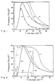
- FIG. 1 is a graphical representation showing the average and projectile base pressure profiles vs. time of a high velocity conventional gun with chemical propulsion and the potential that can be achieved with a hybrid gun according to the invention;
- FIG. 2 is a graphical representation showing the calculated performance and design characteristics of a hybrid gun according to the invention showing the barrel average pressure resulting from each of the electrothermal energy pulses and the burning propellant;
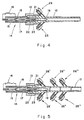
- FIG. 3 is an axial section through a hybrid gun according to the invention with only one electrothermal propulsion energy injector;
- FIG. 4 is an axial section through a hybrid gun according to the invention with three electrothermal propulsion energy injectors;
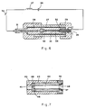
- FIG. 5 is an axial section through a hybrid gun according to the invention with several electrothermal energy injectors along the barrel;
- FIG. 6 is an axial section through a plasma beam generator forming part of an electrothermal propulsion energy injector in a hybrid gun according to the invention; and
- FIG. 7 is an axial section through a working fluid holding chamber in an electrothermal propulsion energy injector of a hybrid gun according to the invention.
- In Fig. 1 the pressure inside the barrel of a gun is plotted vs. the time counted from firing. The first curve 1 shows the average pressure profile in a conventional high velocity gun in which the projectile is accelerated by expanding gases generated by a combusting chemical propellant. This curve is characteristic of the interior ballistics of all conventional guns in the case shown a maximum pressure of 500 MPa is reached after 1.5 m/s.
- The
second curve 2 in Fig. 1 shows the pressure acting on the projectile base and it is seen that as the projectile velocity increases the pressure acting on the projectile base decreases according to equation (II) herein and is significantly smaller than the average pressure in the barrel. -
Curves 3 and 4 show the pressure potential that can be achieved in a hybrid gun of the present invention, mainly that the maximum average pressure can be maintained for a longer period of time, and consequently, the pressure exerted on the projectile base (curve 4) is higher and the Pb/Pav ratio is much higher than in the conventional gun. - It is readily understood by a person skilled in the art that with the lengths and diameters being equal, the pressure profile in a hybrid gun according to the invention ensures better performance and a higher muzzle velocity than can be achieved with a conventional gun.
- It can moreover be shown that the performance of a hybrid gun according to the invention is also superior to a gun with the same length and diameter with exclusive plasma propulsion, since in the hybrid gun only a fraction of the propulsion energy has to be supplied as electrical energy. Consequently a hybrid gun according to the invention can be made practical for many applications since it does not require large cumbersome electrical power sources.
- The manner in which the pressure profile of a hybrid gun according to the invention as shown in an idealized form by way of
curve 2 in Fig. 1 can be achieved in reality, will now be explained. - In accordance with the invention there occurs a synergistic effect between the expanding propellant gases resulting from the combustion of the chemical propellant, and a plasma activated working fluid. In order to achieve the desired result in terms of pressure profile within the barrel, at least three electrothermal injections are required. These injections can be delivered either by the breech-associated injector, or by one or more barrel-associated injectors. As mentioned, the barrel-associated injectors are preferably arranged in pairs with each such pair being mounted in an axi-symmetrical configuration. In many cases one such pair located close to the breech region will be sufficient. In case of guns with long barrels two or more pairs of injectors suitably spaced from each other may be desired.
- Attention is now directed to Fig. 2 in which curve 5 is the normal average pressure profile in a conventional gun with chemical propulsion and it is identical to curve 1 in Fig. 1. In a hybrid gun according to the invention the normal ignition by means of a percussion fuse is replaced by plasma ignition by means of the breech-associated electrothermal propulsion energy injector. For the purpose of the ignition the said injector produces a first pulse shown at 6 and in consequence of that pulse the average pressure profile changes from the shape of
curve 5 to that ofcurve 7 in Fig. 2. - The said breech-associated electrothermal propulsion energy injector is designed to deliver a second pulse shown at 8 in Fig. 2, which has the effect of maintaining the maximum pressure in the barrel for a longer period of time resulting in a profile shown by
curve 9 in Fig. 2. This second pulse can also be injected by a barrel-associated injector. - A third electrothermal pulse shown at 10 in Fig. 2 has two functions: First to extend the period during which the maximum pressure is maintained so that the desired hypervelocity is achieved, and second, it injects more gas with a low molecular weight, i.e., high speed of sound, to serve as a more efficient pressure transfer medium to the projectile base. This pulse is the most energetic electrothermal pulse injected into the barrel and contains most of the electrothermal propulsion energy. The resulting overall pressure vs. time profile in the hybrid gun resulting from the three pulses is presented as curve 11 in Fig. 2.
- The injection of the third pulse can be performed from:
- a) the breech-associated injector
- b) from one set of barrel-associated injectors
- c) a series of barrel-associated injectors located along the barrel and delivering a series of pulses which together approximate the shape of
curve 10. - One should bear in mind that the electrothermal energy injections represented as
curves - It is evident that the correct sequential timing of the various gusts of activated working fluid injected into the gun by means of the breech-associated and barrel-associated electrothermal injectors and the duration of each such injection have to be suitably programmed and this is achieved by means of suitable electronic timing and switching devices known per se.
- The embodiment of the hybrid gun according to the invention shown in Fig. 3 comprises a
barrel 12 with a breech 13 to the rear of which is mounted a breech-associated electrothermalpropulsion energy injector 14 comprising aplasma beam generator 15 with an associated pulse-forming network (PFN) 16, and atubular chamber 17 intermediary between theplasma beam generator 15 andbreech 13, holding a workingfluid 18. -
Breech 13 is shown to hold a round of ammunition comprising a projectile 19 and associatedcartridge 20 holding a suitably selectedconventional chemical propellant 21.Cartridge 20 is fitted with a centralperforated tube 22 lined with a plasticmaterial ablative liner 23 having perforations overlying those oftube 22 and being of a material which upon heating, liberates a light gas.Cartridge 20 bears on a centrallybored boss 24 in the manner shown, the central bore ofboss 24 being in alignment with anozzle 25 ofchamber 17. - The gun also comprises an electronic timing device (not shown) designed to activate in a suitably programmed fashion the
PFN 16 ofinjector 14 so as to produce sequentially at least three plasma pulses. In operation, each time theplasma beam generator 15 ofinjector 14 produces a plasma pulse, a jet of activated workingfluid 18 is injected vianozzle 25 and the the central bore ofseat 24 into thecentral tube 22 ofcartridge 20 and creates a small volume buffer zone near the base ofprojectile 19. On its way the injected hot working fluid ignitespropellant 21. - The first working fluid gust produced by the first plasma pulse may have an approximate flow profile such as profile 6 in Fig. 2. There then follows a second plasma pulse which generates a second gust of working fluid having, for example a flow profile such as the profile of
pulse 8 in Fig. 2, and in a similar way a third plasma pulse generates a third working fluid gust with a flow profile approximately similar to that ofpulse 10 in Fig. 2. - By the combined effect resulting from expansion of the gases from the the combusting
chemical propellant 21 and the first two gusts of activated working fluid injected byinjector 14 and accumulating near the base ofprojectile 19, the latter begins to move along the barrel and at a suitable timing there then follows the third working fluid injection. As a result of the effects resulting from the interaction of the three gusts of activated fluid frominjector 14 with the propellant gases, there forms a pressure profile similar to those ofcurve 3 in Fig. 1 and curve 11 in Fig. 2, and projectile 19 is ejected from the muzzle ofbarrel 12 at a high speed between 1500-4000 m/s. - The embodiment of a hybrid gun according to the invention shown in Fig. 4 comprises in addition to the breech-associated electrothermal propulsion energy injector also two barrel-associated injectors. In Fig. 4 components corresponding to those of the embodiment of Fig. 3 are marked by the same reference numerals. As shown, this embodiment comprises close to the breech 13 a pair of barrel-associated electrothermal
propulsion energy injectors barrel 12. In this embodiment the electronic timing devices (not shown) are designed to activate in a suitably programmed fashion the PFN of the various injectors and appropriate fiberoptics or other sensors are provided to detect the location and speed of the travelling projectile. - Similar as in the embodiment of Fig. 3, the first two working fluid pulses are produced by the barrel-associated
electrothermal energy injector 14. However, as distinct from that embodiment, in the present embodiment the third, booster working fluid pulse is produced by the barrel-associated electrothermalpropulsion energy injectors - The embodiment of a hybrid gun according to the invention shown in Fig. 5 is essentially similar to that of Fig. 4 and corresponding components are again marked by the same reference numerals. In this embodiment the single pair of barrel-associated
electrothermal injectors - The breech associated
plasma beam generator 15 of Figs. 3 and 4 is more closely shown in Fig. 6. As can be seen, it comprises a high strength steel housing 27 fitted with holdingcaps composites 30 and holding acathode 31 and ananode 32. - A
capilary tube 33 made of ablativeplastic material 34links cathode 31 with theanode 32 which latter is centrally bored and comprises an integral, outwardly screw-threadedtubular portion 35 whose central bore is in full alignment withbore 34 and forms an exit nozzle for the plasma. Theplastic material liner 34 is ablated by the electrical current to produce the plasma. - The plasma injector is connected to an electrical pulse forming network (PFN) indicated at 16 in Figs. 3,4 and 5 and which, for the sake of simplicity, is represented here by a
switch 36, aninductor 37 and acapacitor 38. A prime power electrical power supply is used to load electrical energy into the PFN. - Each electrothermal injector also comprises a tubular chamber holding a working fluid such as
chamber 17 in Figs. 3, 4 and 5 and such chamber is more closely shown in Fig. 7. It comprises abody 40 made of high strength material and having a screw threadedinlet nozzle 41 adapted for mounting on the outwardly screw-threadedinjection nozzle 35 of the plasma beam generator of Fig. 6. Thebody 40 is further fitted with aconnector 42 adapted for connection to thebreech 13 of the gun shown in any of Figs. 3, 4 and 5. -
Body 40 holds aliner 43 which upon the passage of a plasma jet is adapted to liberate a working fluid.Liner 43 may, for example, be in the form of an absorbent material soaked with working fluid or alternatively in the form of a gel or the whole space might be filled with a light gas forming substance. - The
tubular chamber 44 ofbody 40 serves as the mixing chamber in which the plasma jet arriving from the generator of Fig. 6 mixes with working fluid in said chamber. - Adjacent to the
inlet nozzle 41 there is anannular member 45 of high temperature resisting material with aconical aperture 46, and a secondannular body 47 of high temperature resisting material near the opposite end and having aconical aperture 48 serves as exit nozzle for the activated working fluid.
Claims (10)
- A gun for launching a projectile (19) having a barrel (12) and breech (13) comprising electrothermal propulsion energy injector means (14) including a plasma beam generator (15) for the acceleration of said projectiles; and
electric starter means (16) for the energization of said electrothermal propulsion energy injector means, characterized in that
said projectile is a chemical propellant bearing projectile (19) holding a chemical propellant (21);
said electrothermal propulsion energy injector means (14) is associated with the breech (13) of said gun and is located to the rear thereof and includes intermediary of said plasma beam generator (15) and said breech (13) an aligned tubular chamber (17) having a nozzle (25) opening into said breech (13) and holding a light working fluid (18) having a molecular weight not exceeding that of said chemical propellant;
said electric starter means (16) energizes said breech-associated electrothermal propulsion energy injector means (14) in a pulsating successive manner whereby said injector means (14) ejects desired jets of activated gaseous light working fluid into a cartridge (20) of said chemical propellant bearing projectile; and in that
said gun is a hybrid gun which launches said chemical propellant bearing projectile (19) by a combined propulsion effect produced by said chemical propellant (21) and by the electrothermal energy from said electrothermal propulsion energy injector means (14). - A hybrid gun according to claim 1 comprising at least one barrel-associated electrothermal propulsion energy injector (25,26) mounted on the barrel (12) and comprising a plasma beam injector and intermediary thereof and the barrel an aligned tubular chamber having a nozzle opening into the barrel and holding a working fluid having a molecular weight not exceeding that of the said chemical propellant.
- A hybrid gun according to claim 2, wherein the barrel-associated electrothermal propulsion energy injectors are arranged pairwise (25,26) with each pair being mounted on the barrel in axi-symmetrical configuration with respect to the longitudinal axis of the barrel.
- A hybrid gun according to claim 3 comprising a single pair of electrothermal propulsion energy injectors.
- A hybrid gun according to claim 4 comprising several pairs of electrothermal propulsion energy injectors.
- A method of converting a conventional gun into a hybrid gun according to claim 1, comprising providing at the rear of the breech an electrothermal propulsion energy injector (14) comprising in mutual alignment a plasma beam generator (15) and a tubular chamber (17) fitted with an injection nozzle (25) and holding a working fluid (18) having a molecular weight not exceeding that of the chemical propellant of the designated ammunition.
- A method according to claim 6, comprising in addition replacing an existing barrel by a barrel fitted with at least one electrothermal propulsion energy injector having in mutual alignment a plasma beam generator and a tubular chamber fitted with a nozzle and holding a working fluid having a molecular weight not exceeding that of the said chemical propellant.
- For use in a hybrid gun according to any one of claims 1 to 5 and 6 to 7, an electrothermal propulsion energy injector device (14) comprising in mutual alignment a plasma beam generator (15) and a tubular chamber (17) fitted with an injection nozzle (25) and holding a working fluid (18).
- For use with a hybrid gun according to any one of claims 1 to 5 and 6 to 7, a piece of ammunition comprising a projectile (19) and a cartridge (20) holding a chemical propellant (21) and having an axially extending hollow, perforated tube (22) open at the cartridge base and leading to the projectile base.
- Ammunition according to claim 9, wherein the inner side of the perforated tube (22) is lined with an ablative material (23) which upon heating releases a light gaseous phase.
Applications Claiming Priority (2)
| Application Number | Priority Date | Filing Date | Title |
|---|---|---|---|
| IL89231A IL89231A (en) | 1989-02-09 | 1989-02-09 | Gun with combined operation by explosive material and plasma |
| IL89231 | 1989-02-09 |
Publications (3)
| Publication Number | Publication Date |
|---|---|
| EP0382000A2 EP0382000A2 (en) | 1990-08-16 |
| EP0382000A3 EP0382000A3 (en) | 1991-04-03 |
| EP0382000B1 true EP0382000B1 (en) | 1994-04-20 |
Family
ID=11059673
Family Applications (1)
| Application Number | Title | Priority Date | Filing Date |
|---|---|---|---|
| EP90101414A Expired - Lifetime EP0382000B1 (en) | 1989-02-09 | 1990-01-24 | A gun with combined operation by chemical propellant and plasma |
Country Status (7)
| Country | Link |
|---|---|
| EP (1) | EP0382000B1 (en) |
| AT (1) | ATE104764T1 (en) |
| DE (1) | DE69008208T2 (en) |
| DK (1) | DK0382000T3 (en) |
| ES (1) | ES2055811T3 (en) |
| IE (1) | IE63049B1 (en) |
| IL (1) | IL89231A (en) |
Families Citing this family (6)
| Publication number | Priority date | Publication date | Assignee | Title |
|---|---|---|---|---|
| DE4039089A1 (en) * | 1990-12-07 | 1992-06-11 | Diehl Gmbh & Co | Electrically heated plasma projectile gun - uses electric discharge circuit between two electrodes mutually spaced in pressure or plasma chamber with its front closure formed by projectile |
| US5225624A (en) * | 1991-12-16 | 1993-07-06 | Fmc Corporation | Disintegrating injector for primary and fuel enriched plasma |
| US5355764A (en) * | 1992-05-04 | 1994-10-18 | Fmc Corporation | Plasma actuated ignition and distribution pump |
| US5574240A (en) * | 1992-12-07 | 1996-11-12 | Hercules Incorporated | Propellants useful in electrothermal-chemical guns |
| FR2768810B1 (en) * | 1997-09-24 | 1999-12-03 | Giat Ind Sa | IGNITION COMPONENT FOR PYROTECHNIC COMPOSITION OR PROPULSIVE CHARGE |
| US7059249B2 (en) | 2001-01-23 | 2006-06-13 | United Defense Lp | Transverse plasma injector ignitor |
Family Cites Families (2)
| Publication number | Priority date | Publication date | Assignee | Title |
|---|---|---|---|---|
| US4590842A (en) * | 1983-03-01 | 1986-05-27 | Gt-Devices | Method of and apparatus for accelerating a projectile |
| IL85622A (en) * | 1988-03-03 | 1992-08-18 | Israel Atomic Energy Comm | Method and apparatus for accelerating projectiles |
-
1989
- 1989-02-09 IL IL89231A patent/IL89231A/en not_active IP Right Cessation
-
1990
- 1990-01-23 IE IE25990A patent/IE63049B1/en not_active IP Right Cessation
- 1990-01-24 EP EP90101414A patent/EP0382000B1/en not_active Expired - Lifetime
- 1990-01-24 DE DE69008208T patent/DE69008208T2/en not_active Expired - Fee Related
- 1990-01-24 ES ES90101414T patent/ES2055811T3/en not_active Expired - Lifetime
- 1990-01-24 AT AT9090101414T patent/ATE104764T1/en not_active IP Right Cessation
- 1990-01-24 DK DK90101414.2T patent/DK0382000T3/en active
Also Published As
| Publication number | Publication date |
|---|---|
| IE900259L (en) | 1990-08-09 |
| DK0382000T3 (en) | 1994-06-06 |
| ATE104764T1 (en) | 1994-05-15 |
| EP0382000A2 (en) | 1990-08-16 |
| DE69008208T2 (en) | 1994-08-04 |
| ES2055811T3 (en) | 1994-09-01 |
| IL89231A (en) | 1992-11-15 |
| DE69008208D1 (en) | 1994-05-26 |
| IE63049B1 (en) | 1995-03-22 |
| IL89231A0 (en) | 1989-09-10 |
| EP0382000A3 (en) | 1991-04-03 |
Similar Documents
| Publication | Publication Date | Title |
|---|---|---|
| US5233903A (en) | Gun with combined operation by chemical propellant and plasma | |
| US5355764A (en) | Plasma actuated ignition and distribution pump | |
| CA1290178C (en) | Armament system | |
| US4726279A (en) | Wake stabilized supersonic combustion ram cannon | |
| US4722261A (en) | Extendable ram cannon | |
| US4938112A (en) | Apparatus and method for the acceleration of projectiles to hypervelocities | |
| US4126955A (en) | High velocity tapered bore gun and ammunition | |
| US5171932A (en) | Electrothermal chemical propulsion apparatus and method for propelling a projectile | |
| US5016518A (en) | Method and apparatus for accelerating projectiles | |
| EP0382000B1 (en) | A gun with combined operation by chemical propellant and plasma | |
| US4132149A (en) | Liquid propellant weapon system | |
| US4126078A (en) | Liquid propellant weapon system | |
| US5322002A (en) | Tube launched weapon system | |
| USH403H (en) | Gun launched kinetic energy penetrator | |
| SE0500581A1 (en) | Plasma lighters for an electrochemical-chemical (ETK) cannon, bullet gun or other firearm weapon of similar type | |
| US5503058A (en) | Vectored plasma arc device | |
| JPH024197A (en) | Gun device using liquefied gunpowder | |
| US4102269A (en) | Liquid propellant weapon system | |
| Kaplan et al. | Electrothermally augmentation of a solid propellant launcher | |
| US6202560B1 (en) | Explosively started projectile gun ammunition | |
| US3465639A (en) | Hypervelocity jet and projectile velocity augmenter | |
| US5631436A (en) | Gun equipped with down-bore liquid propellant booster stage to increase projectile muzzle velocity | |
| Higgins et al. | Gasdynamic operation of baffled tube ram accelerator in highly energetic mixtures | |
| US5131313A (en) | Linear accelerator | |
| US6868790B1 (en) | High velocity underwater jet weapon |
Legal Events
| Date | Code | Title | Description |
|---|---|---|---|
| PUAI | Public reference made under article 153(3) epc to a published international application that has entered the european phase |
Free format text: ORIGINAL CODE: 0009012 |
|
| AK | Designated contracting states |
Kind code of ref document: A2 Designated state(s): AT BE CH DE DK ES FR GB GR IT LI LU NL SE |
|
| PUAL | Search report despatched |
Free format text: ORIGINAL CODE: 0009013 |
|
| AK | Designated contracting states |
Kind code of ref document: A3 Designated state(s): AT BE CH DE DK ES FR GB GR IT LI LU NL |
|
| 17P | Request for examination filed |
Effective date: 19910524 |
|
| 17Q | First examination report despatched |
Effective date: 19920518 |
|
| GRAA | (expected) grant |
Free format text: ORIGINAL CODE: 0009210 |
|
| AK | Designated contracting states |
Kind code of ref document: B1 Designated state(s): AT BE CH DE DK ES FR GB GR IT LI LU NL SE |
|
| REF | Corresponds to: |
Ref document number: 104764 Country of ref document: AT Date of ref document: 19940515 Kind code of ref document: T |
|
| REF | Corresponds to: |
Ref document number: 69008208 Country of ref document: DE Date of ref document: 19940526 |
|
| REG | Reference to a national code |
Ref country code: DK Ref legal event code: T3 |
|
| ITF | It: translation for a ep patent filed |
Owner name: PROPRIA PROT. PROPRIETA' IND. |
|
| REG | Reference to a national code |
Ref country code: GR Ref legal event code: FG4A Free format text: 3011927 |
|
| ET | Fr: translation filed | ||
| REG | Reference to a national code |
Ref country code: ES Ref legal event code: FG2A Ref document number: 2055811 Country of ref document: ES Kind code of ref document: T3 |
|
| EAL | Se: european patent in force in sweden |
Ref document number: 90101414.2 |
|
| PLBE | No opposition filed within time limit |
Free format text: ORIGINAL CODE: 0009261 |
|
| STAA | Information on the status of an ep patent application or granted ep patent |
Free format text: STATUS: NO OPPOSITION FILED WITHIN TIME LIMIT |
|
| 26N | No opposition filed | ||
| PGFP | Annual fee paid to national office [announced via postgrant information from national office to epo] |
Ref country code: GB Payment date: 19970122 Year of fee payment: 8 |
|
| PGFP | Annual fee paid to national office [announced via postgrant information from national office to epo] |
Ref country code: FR Payment date: 19970127 Year of fee payment: 8 |
|
| PGFP | Annual fee paid to national office [announced via postgrant information from national office to epo] |
Ref country code: SE Payment date: 19970129 Year of fee payment: 8 Ref country code: DK Payment date: 19970129 Year of fee payment: 8 Ref country code: AT Payment date: 19970129 Year of fee payment: 8 |
|
| PGFP | Annual fee paid to national office [announced via postgrant information from national office to epo] |
Ref country code: GR Payment date: 19970130 Year of fee payment: 8 |
|
| PGFP | Annual fee paid to national office [announced via postgrant information from national office to epo] |
Ref country code: NL Payment date: 19970131 Year of fee payment: 8 Ref country code: ES Payment date: 19970131 Year of fee payment: 8 Ref country code: DE Payment date: 19970131 Year of fee payment: 8 |
|
| PGFP | Annual fee paid to national office [announced via postgrant information from national office to epo] |
Ref country code: CH Payment date: 19970206 Year of fee payment: 8 |
|
| PGFP | Annual fee paid to national office [announced via postgrant information from national office to epo] |
Ref country code: BE Payment date: 19970318 Year of fee payment: 8 |
|
| PGFP | Annual fee paid to national office [announced via postgrant information from national office to epo] |
Ref country code: LU Payment date: 19970327 Year of fee payment: 8 |
|
| PG25 | Lapsed in a contracting state [announced via postgrant information from national office to epo] |
Ref country code: LU Free format text: LAPSE BECAUSE OF NON-PAYMENT OF DUE FEES Effective date: 19980124 Ref country code: GB Free format text: LAPSE BECAUSE OF NON-PAYMENT OF DUE FEES Effective date: 19980124 Ref country code: AT Free format text: LAPSE BECAUSE OF NON-PAYMENT OF DUE FEES Effective date: 19980124 |
|
| PG25 | Lapsed in a contracting state [announced via postgrant information from national office to epo] |
Ref country code: SE Free format text: LAPSE BECAUSE OF NON-PAYMENT OF DUE FEES Effective date: 19980125 |
|
| PG25 | Lapsed in a contracting state [announced via postgrant information from national office to epo] |
Ref country code: ES Free format text: LAPSE BECAUSE OF NON-PAYMENT OF DUE FEES Effective date: 19980126 |
|
| PG25 | Lapsed in a contracting state [announced via postgrant information from national office to epo] |
Ref country code: LI Free format text: LAPSE BECAUSE OF NON-PAYMENT OF DUE FEES Effective date: 19980131 Ref country code: GR Free format text: LAPSE BECAUSE OF NON-PAYMENT OF DUE FEES Effective date: 19980131 Ref country code: FR Free format text: THE PATENT HAS BEEN ANNULLED BY A DECISION OF A NATIONAL AUTHORITY Effective date: 19980131 Ref country code: CH Free format text: LAPSE BECAUSE OF NON-PAYMENT OF DUE FEES Effective date: 19980131 Ref country code: BE Free format text: LAPSE BECAUSE OF NON-PAYMENT OF DUE FEES Effective date: 19980131 |
|
| PG25 | Lapsed in a contracting state [announced via postgrant information from national office to epo] |
Ref country code: DK Free format text: LAPSE BECAUSE OF NON-PAYMENT OF DUE FEES Effective date: 19980202 |
|
| BERE | Be: lapsed |
Owner name: THE STATE OF ISRAEL ATOMIC ENERGY COMMISSION SORE Effective date: 19980131 |
|
| PG25 | Lapsed in a contracting state [announced via postgrant information from national office to epo] |
Ref country code: NL Free format text: LAPSE BECAUSE OF NON-PAYMENT OF DUE FEES Effective date: 19980801 |
|
| REG | Reference to a national code |
Ref country code: CH Ref legal event code: PL |
|
| GBPC | Gb: european patent ceased through non-payment of renewal fee |
Effective date: 19980124 |
|
| NLV4 | Nl: lapsed or anulled due to non-payment of the annual fee |
Effective date: 19980801 |
|
| PG25 | Lapsed in a contracting state [announced via postgrant information from national office to epo] |
Ref country code: DE Free format text: LAPSE BECAUSE OF NON-PAYMENT OF DUE FEES Effective date: 19981001 |
|
| EUG | Se: european patent has lapsed |
Ref document number: 90101414.2 |
|
| REG | Reference to a national code |
Ref country code: FR Ref legal event code: ST |
|
| REG | Reference to a national code |
Ref country code: DK Ref legal event code: EBP |
|
| REG | Reference to a national code |
Ref country code: ES Ref legal event code: FD2A Effective date: 20000503 |
|
| PG25 | Lapsed in a contracting state [announced via postgrant information from national office to epo] |
Ref country code: IT Free format text: LAPSE BECAUSE OF NON-PAYMENT OF DUE FEES;WARNING: LAPSES OF ITALIAN PATENTS WITH EFFECTIVE DATE BEFORE 2007 MAY HAVE OCCURRED AT ANY TIME BEFORE 2007. THE CORRECT EFFECTIVE DATE MAY BE DIFFERENT FROM THE ONE RECORDED. Effective date: 20050124 |