EP0381307B1 - Disc brake and cap seal therefor - Google Patents
Disc brake and cap seal therefor Download PDFInfo
- Publication number
- EP0381307B1 EP0381307B1 EP90300058A EP90300058A EP0381307B1 EP 0381307 B1 EP0381307 B1 EP 0381307B1 EP 90300058 A EP90300058 A EP 90300058A EP 90300058 A EP90300058 A EP 90300058A EP 0381307 B1 EP0381307 B1 EP 0381307B1
- Authority
- EP
- European Patent Office
- Prior art keywords
- seal
- caliper
- cap seal
- axial bore
- stationary support
- Prior art date
- Legal status (The legal status is an assumption and is not a legal conclusion. Google has not performed a legal analysis and makes no representation as to the accuracy of the status listed.)
- Expired - Lifetime
Links
- 239000000463 material Substances 0.000 claims abstract description 11
- 238000007789 sealing Methods 0.000 claims abstract description 6
- 239000000853 adhesive Substances 0.000 claims description 3
- 230000001070 adhesive effect Effects 0.000 claims description 3
- 239000011324 bead Substances 0.000 description 4
- 239000007788 liquid Substances 0.000 description 3
- 229910000831 Steel Inorganic materials 0.000 description 1
- 239000006260 foam Substances 0.000 description 1
- 239000007769 metal material Substances 0.000 description 1
- 239000011347 resin Substances 0.000 description 1
- 229920005989 resin Polymers 0.000 description 1
- 238000009987 spinning Methods 0.000 description 1
- 239000010959 steel Substances 0.000 description 1
Images


Classifications
-
- F—MECHANICAL ENGINEERING; LIGHTING; HEATING; WEAPONS; BLASTING
- F16—ENGINEERING ELEMENTS AND UNITS; GENERAL MEASURES FOR PRODUCING AND MAINTAINING EFFECTIVE FUNCTIONING OF MACHINES OR INSTALLATIONS; THERMAL INSULATION IN GENERAL
- F16D—COUPLINGS FOR TRANSMITTING ROTATION; CLUTCHES; BRAKES
- F16D65/00—Parts or details
-
- F—MECHANICAL ENGINEERING; LIGHTING; HEATING; WEAPONS; BLASTING
- F16—ENGINEERING ELEMENTS AND UNITS; GENERAL MEASURES FOR PRODUCING AND MAINTAINING EFFECTIVE FUNCTIONING OF MACHINES OR INSTALLATIONS; THERMAL INSULATION IN GENERAL
- F16D—COUPLINGS FOR TRANSMITTING ROTATION; CLUTCHES; BRAKES
- F16D55/00—Brakes with substantially-radial braking surfaces pressed together in axial direction, e.g. disc brakes
- F16D55/02—Brakes with substantially-radial braking surfaces pressed together in axial direction, e.g. disc brakes with axially-movable discs or pads pressed against axially-located rotating members
- F16D55/22—Brakes with substantially-radial braking surfaces pressed together in axial direction, e.g. disc brakes with axially-movable discs or pads pressed against axially-located rotating members by clamping an axially-located rotating disc between movable braking members, e.g. movable brake discs or brake pads
- F16D55/224—Brakes with substantially-radial braking surfaces pressed together in axial direction, e.g. disc brakes with axially-movable discs or pads pressed against axially-located rotating members by clamping an axially-located rotating disc between movable braking members, e.g. movable brake discs or brake pads with a common actuating member for the braking members
- F16D55/225—Brakes with substantially-radial braking surfaces pressed together in axial direction, e.g. disc brakes with axially-movable discs or pads pressed against axially-located rotating members by clamping an axially-located rotating disc between movable braking members, e.g. movable brake discs or brake pads with a common actuating member for the braking members the braking members being brake pads
- F16D55/226—Brakes with substantially-radial braking surfaces pressed together in axial direction, e.g. disc brakes with axially-movable discs or pads pressed against axially-located rotating members by clamping an axially-located rotating disc between movable braking members, e.g. movable brake discs or brake pads with a common actuating member for the braking members the braking members being brake pads in which the common actuating member is moved axially, e.g. floating caliper disc brakes
- F16D55/2265—Brakes with substantially-radial braking surfaces pressed together in axial direction, e.g. disc brakes with axially-movable discs or pads pressed against axially-located rotating members by clamping an axially-located rotating disc between movable braking members, e.g. movable brake discs or brake pads with a common actuating member for the braking members the braking members being brake pads in which the common actuating member is moved axially, e.g. floating caliper disc brakes the axial movement being guided by one or more pins engaging bores in the brake support or the brake housing
- F16D55/227—Brakes with substantially-radial braking surfaces pressed together in axial direction, e.g. disc brakes with axially-movable discs or pads pressed against axially-located rotating members by clamping an axially-located rotating disc between movable braking members, e.g. movable brake discs or brake pads with a common actuating member for the braking members the braking members being brake pads in which the common actuating member is moved axially, e.g. floating caliper disc brakes the axial movement being guided by one or more pins engaging bores in the brake support or the brake housing by two or more pins
-
- F—MECHANICAL ENGINEERING; LIGHTING; HEATING; WEAPONS; BLASTING
- F16—ENGINEERING ELEMENTS AND UNITS; GENERAL MEASURES FOR PRODUCING AND MAINTAINING EFFECTIVE FUNCTIONING OF MACHINES OR INSTALLATIONS; THERMAL INSULATION IN GENERAL
- F16D—COUPLINGS FOR TRANSMITTING ROTATION; CLUTCHES; BRAKES
- F16D55/00—Brakes with substantially-radial braking surfaces pressed together in axial direction, e.g. disc brakes
- F16D55/02—Brakes with substantially-radial braking surfaces pressed together in axial direction, e.g. disc brakes with axially-movable discs or pads pressed against axially-located rotating members
- F16D55/22—Brakes with substantially-radial braking surfaces pressed together in axial direction, e.g. disc brakes with axially-movable discs or pads pressed against axially-located rotating members by clamping an axially-located rotating disc between movable braking members, e.g. movable brake discs or brake pads
- F16D55/224—Brakes with substantially-radial braking surfaces pressed together in axial direction, e.g. disc brakes with axially-movable discs or pads pressed against axially-located rotating members by clamping an axially-located rotating disc between movable braking members, e.g. movable brake discs or brake pads with a common actuating member for the braking members
- F16D55/225—Brakes with substantially-radial braking surfaces pressed together in axial direction, e.g. disc brakes with axially-movable discs or pads pressed against axially-located rotating members by clamping an axially-located rotating disc between movable braking members, e.g. movable brake discs or brake pads with a common actuating member for the braking members the braking members being brake pads
- F16D55/226—Brakes with substantially-radial braking surfaces pressed together in axial direction, e.g. disc brakes with axially-movable discs or pads pressed against axially-located rotating members by clamping an axially-located rotating disc between movable braking members, e.g. movable brake discs or brake pads with a common actuating member for the braking members the braking members being brake pads in which the common actuating member is moved axially, e.g. floating caliper disc brakes
- F16D55/2265—Brakes with substantially-radial braking surfaces pressed together in axial direction, e.g. disc brakes with axially-movable discs or pads pressed against axially-located rotating members by clamping an axially-located rotating disc between movable braking members, e.g. movable brake discs or brake pads with a common actuating member for the braking members the braking members being brake pads in which the common actuating member is moved axially, e.g. floating caliper disc brakes the axial movement being guided by one or more pins engaging bores in the brake support or the brake housing
-
- F—MECHANICAL ENGINEERING; LIGHTING; HEATING; WEAPONS; BLASTING
- F16—ENGINEERING ELEMENTS AND UNITS; GENERAL MEASURES FOR PRODUCING AND MAINTAINING EFFECTIVE FUNCTIONING OF MACHINES OR INSTALLATIONS; THERMAL INSULATION IN GENERAL
- F16D—COUPLINGS FOR TRANSMITTING ROTATION; CLUTCHES; BRAKES
- F16D55/00—Brakes with substantially-radial braking surfaces pressed together in axial direction, e.g. disc brakes
- F16D55/02—Brakes with substantially-radial braking surfaces pressed together in axial direction, e.g. disc brakes with axially-movable discs or pads pressed against axially-located rotating members
- F16D55/22—Brakes with substantially-radial braking surfaces pressed together in axial direction, e.g. disc brakes with axially-movable discs or pads pressed against axially-located rotating members by clamping an axially-located rotating disc between movable braking members, e.g. movable brake discs or brake pads
- F16D55/224—Brakes with substantially-radial braking surfaces pressed together in axial direction, e.g. disc brakes with axially-movable discs or pads pressed against axially-located rotating members by clamping an axially-located rotating disc between movable braking members, e.g. movable brake discs or brake pads with a common actuating member for the braking members
- F16D55/225—Brakes with substantially-radial braking surfaces pressed together in axial direction, e.g. disc brakes with axially-movable discs or pads pressed against axially-located rotating members by clamping an axially-located rotating disc between movable braking members, e.g. movable brake discs or brake pads with a common actuating member for the braking members the braking members being brake pads
- F16D55/226—Brakes with substantially-radial braking surfaces pressed together in axial direction, e.g. disc brakes with axially-movable discs or pads pressed against axially-located rotating members by clamping an axially-located rotating disc between movable braking members, e.g. movable brake discs or brake pads with a common actuating member for the braking members the braking members being brake pads in which the common actuating member is moved axially, e.g. floating caliper disc brakes
- F16D55/2265—Brakes with substantially-radial braking surfaces pressed together in axial direction, e.g. disc brakes with axially-movable discs or pads pressed against axially-located rotating members by clamping an axially-located rotating disc between movable braking members, e.g. movable brake discs or brake pads with a common actuating member for the braking members the braking members being brake pads in which the common actuating member is moved axially, e.g. floating caliper disc brakes the axial movement being guided by one or more pins engaging bores in the brake support or the brake housing
- F16D55/22655—Constructional details of guide pins
Definitions
- This invention relates to a disc brake for a motor vehicle, and to a cap seal for the disc brake.
- Disc brakes which comprise a stationary support for mounting on a motor vehicle, a caliper slidably mounted on the stationary support, and at least one pin fixed to either the stationary support or the caliper and slidably inserted in an axial bore in the other.
- a cap seal in order to prevent dirt and/or moisture reaching the sliding surfaces.
- these cap seals do not always seal as required.
- Such a known arrangement is shown in GB Patent No. 1563405.
- a disc brake for a motor vehicle in accordance with the present invention comprises a stationary support for mounting on the motor vehicle; a caliper slidably mounted on the stationary support; at least one pin fixed at one end to either the stationary support or the caliper and slidably positioned in an axial bore in the other for slidably mounting the caliper, with the other end of the pin being positioned at or adjacent one end of the axial bore; and a cap seal sealing the said one end of the axial bore, the cap seal comprising a base with a continuous wall upstanding from the periphery thereof which is of substantially rigid material and which is securable to the said other of the stationary support or the caliper, and an elastomeric seal secured to the continuous wall for making a seal with the said other of the stationary support or the caliper around the said one end of the axial bore.
- the said other of the stationary support or the caliper has an annularly extending ledge formed therein around the said one end of the axial bore, and the continuous wall of the cap seal is resilient and makes an external push fit with the annularly extending ledge to secure the cap seal.
- the said other of the stationary support or the caliper may have a ridge formed therein around the said one end of the axial bore, with the continuous wall of the cap seal being resilient and making a snap fit with the ridge to secure the cap seal.
- the said other of the stationary support or the caliper may have an annularly extending groove formed therein around the said one end of the axial bore, with the continuous wall of the cap seal being resilient and making an internal push fit with the annularly extending groove to secure the cap seal.
- the elastomeric seal of the cap seal is preferably of rubber and is secured by adhesive to the continuous wall of the cap seal.
- the elastomeric seal is preferably secured to the free edge of the continuous wall.
- the elastomeric seal of the cap seal may be of polymeric material which is secured by sticking to the continuous wall during polymerising of the material.
- the elastomeric seal is preferably secured to the inner surface of the continuous wall.
- the disc brake 10 comprises a caliper 12 which is slidably mountable on a stationary support (not shown).
- the slidable mounting is provided by two pins 14 which are spaced apart, and each of which is slidably positioned in an axial bore 16 in the caliper 12.
- Each pin 14 is defined by a hollow sleeve 18 of steel and a bolt 20 which passes through the hollow sleeve and is screw threaded at one end 22 to the stationary support.
- Each hollow sleeve 18 extends through its respective axial bore 16 and has an outer surface 24 in sliding engagement with the surface 28 of the axial bore.
- the other end or head 30 of the bolt 20 is positioned in the hollow sleeve 18 at or adjacent one end 32 of the axial bore 16.
- annularly extending ledge 34 is formed in the caliper 12 around the one end 32.
- a cap seal 36, 36′ engages the annularly extending ledge 34 to substantially prevent dirt and/or moisture reaching the sliding surfaces 24,28.
- the cap seal 36, 36′ is described in more detail with reference to Figures 2A and 2B respectively in which the bolt 20 has been omitted for clarity.
- the cap seal 36, 36′ comprises a base 38 having a continuous wall 40 upstanding from the periphery of the base and integral therewith.
- the base 38 and continuous walls 40 are substantially rigid.
- the material of the continuous wall 40 (which is usually made from metallic material) is such that the continuous wall is resilient, and when pushed on to the annularly extending ledge 34, grips the annularly extending ledge to hold the cap seal 36, 36′ in position.
- an elastomeric seal 42 of rubber is bonded by a suitable adhesive to the free edge 44 of the continuous wall 40.
- the elastomeric seal 42 engages the annularly extending ledge to form a seal therewith around the one end 32 of the axial bore 16.
- an elastomeric seal 42′ of polymeric material (such as PVC) is defined by a bead 46 which is circumferentially positioned around the inner surface 48 of the continuous wall 40.
- the bead 46 engages the annularly extending ledge 34 when the cap seal 36′ is pushed into position to form a seal around the one end 32 of the axial bore 16.
- the bead 46 can be formed by dripping the polymeric material in liquid form onto the inner surface 48 of the continuous wall 40, and then spinning the cap seal 36′ to spread the liquid. The liquid is such that it sticks and foams as it dries (polymerises) to form the bead 46.
- the disc brake comprises a caliper 52 slidably mounted on a stationary support 54 by pins 56 and 58.
- Pin 56 comprises a hollow sleeve 60 with a bolt 62 passing through the hollow sleeve and screw threaded to the stationary support.
- the pin 56 is slidably mounted in an axial bore 64 in the caliper 52. Sealing boots 66 seal each end of the axial bore 64.
- Bolt 62 can be removed to allow the caliper 52 to rotate about the axis 67 of the pin 58 relative to the stationary support 54.
- Pin 58 is in one-piece and is screw threaded at one end 68 to the stationary support 54 with the other end 70 of the pin passing through another axial bore 72 in the caliper 52.
- the other end 70 of the pin 58 is positioned at or adjacent one end 74 of the axial bore 72, with the outer surface 76 of the pin 58 slidingly engaging the inner surface 78 of the axial bore 72.
- An annularly extending ledge 80 is formed on the caliper 52 around the one end 74 of the axial bore 72.
- a cap seal 82 which is substantially identical to the cap seal 36 shown in Figure 2A, seals the one end 74 of the axial bore 72 to substantially prevent dirt and/or moisture reaching the sliding surfaces 76,78 through the one end 74.
- cap seal 92 is substantially identical to the cap seal 36′ shown in Figure 2B.
- cap seals having a continuous wall which makes an external push fit onto an annularly extending ledge
- the free end of the continuous wall of the cap seal may make a snap fit with either an outwardly directed ridge or an inwardly directed ridge around the one end of the axial bore.
- the continuous wall may be an internal push fit into an annularly extending groove around the one end of the axial bore.
- the elastomeric seal is secured to the continuous wall to seal the one end of the axial bore.
- Alternative arrangements to those disclosed above include bonding the rubber elastomeric seal to the continuous wall in any other suitable position apart from at the free edge thereof.
- the elastomeric seal may be secured to the outer surface of the continuous wall.
Landscapes
- Engineering & Computer Science (AREA)
- General Engineering & Computer Science (AREA)
- Mechanical Engineering (AREA)
- Braking Arrangements (AREA)
Abstract
Description
- This invention relates to a disc brake for a motor vehicle, and to a cap seal for the disc brake.
- Disc brakes are known which comprise a stationary support for mounting on a motor vehicle, a caliper slidably mounted on the stationary support, and at least one pin fixed to either the stationary support or the caliper and slidably inserted in an axial bore in the other. In such arrangements, it is known to seal the axial bore at the exposed end of the pin with a cap seal in order to prevent dirt and/or moisture reaching the sliding surfaces. However, it has been found that these cap seals do not always seal as required. Such a known arrangement is shown in GB Patent No. 1563405.
- Several attempts have been made to overcome this problem. For example, in GB-A-2160600 where both parts of the seal devices are separated from each other and the external part is made of an elastic resin. Also, in GB-A-2158891 where the seal is not at the cap of the pin and is held in position by a ring of reinforced material.
- It is an object of the present invention to provide an arrangement in which a more efficient seal is provided.
- To this end, a disc brake for a motor vehicle in accordance with the present invention comprises a stationary support for mounting on the motor vehicle; a caliper slidably mounted on the stationary support; at least one pin fixed at one end to either the stationary support or the caliper and slidably positioned in an axial bore in the other for slidably mounting the caliper, with the other end of the pin being positioned at or adjacent one end of the axial bore; and a cap seal sealing the said one end of the axial bore, the cap seal comprising a base with a continuous wall upstanding from the periphery thereof which is of substantially rigid material and which is securable to the said other of the stationary support or the caliper, and an elastomeric seal secured to the continuous wall for making a seal with the said other of the stationary support or the caliper around the said one end of the axial bore.
- Preferably, the said other of the stationary support or the caliper has an annularly extending ledge formed therein around the said one end of the axial bore, and the continuous wall of the cap seal is resilient and makes an external push fit with the annularly extending ledge to secure the cap seal. Alternatively, the said other of the stationary support or the caliper may have a ridge formed therein around the said one end of the axial bore, with the continuous wall of the cap seal being resilient and making a snap fit with the ridge to secure the cap seal. As a further alternative, the said other of the stationary support or the caliper may have an annularly extending groove formed therein around the said one end of the axial bore, with the continuous wall of the cap seal being resilient and making an internal push fit with the annularly extending groove to secure the cap seal.
- The elastomeric seal of the cap seal is preferably of rubber and is secured by adhesive to the continuous wall of the cap seal. In this case, the elastomeric seal is preferably secured to the free edge of the continuous wall.
- Alternatively, the elastomeric seal of the cap seal may be of polymeric material which is secured by sticking to the continuous wall during polymerising of the material. In this case, the elastomeric seal is preferably secured to the inner surface of the continuous wall.
- In the present invention, a substantial improvement in the sealing of the cap seal has been found compared to the previously known arrangements.
- The present invention will now be described, by way of example, with reference to the accompanying drawings, in which:-
- Figure 1 is a perspective view, partially cut away, of a first embodiment of disc brake in accordance with the present invention;
- Figures 2A and 2B are alternative cross-sectional views of the cap seal and axial bore in area II of Figure 1;
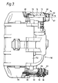
- Figure 3 is a top view, partially cut away, of a second embodiment of brake caliper in accordance with the present invention; and
- Figure 4 is a top view, partially cut away, of a third embodiment of brake caliper in accordance with the present invention.
- Referring to Figure 1 of the accompanying drawings, the
disc brake 10 comprises a caliper 12 which is slidably mountable on a stationary support (not shown). The slidable mounting is provided by twopins 14 which are spaced apart, and each of which is slidably positioned in anaxial bore 16 in the caliper 12. Eachpin 14 is defined by ahollow sleeve 18 of steel and abolt 20 which passes through the hollow sleeve and is screw threaded at oneend 22 to the stationary support. Eachhollow sleeve 18 extends through its respectiveaxial bore 16 and has anouter surface 24 in sliding engagement with thesurface 28 of the axial bore. The other end orhead 30 of thebolt 20 is positioned in thehollow sleeve 18 at or adjacent oneend 32 of theaxial bore 16. - At the one
end 32 of theaxial bore 16, an annularly extendingledge 34 is formed in the caliper 12 around the oneend 32. Acap seal ledge 34 to substantially prevent dirt and/or moisture reaching thesliding surfaces cap seal bolt 20 has been omitted for clarity. In both Figures 2A and 2B thecap seal base 38 having acontinuous wall 40 upstanding from the periphery of the base and integral therewith. Thebase 38 andcontinuous walls 40 are substantially rigid. The material of the continuous wall 40 (which is usually made from metallic material) is such that the continuous wall is resilient, and when pushed on to the annularly extendingledge 34, grips the annularly extending ledge to hold thecap seal elastomeric seal 42 of rubber is bonded by a suitable adhesive to thefree edge 44 of thecontinuous wall 40. On pushing thecap seal 36 on to the annularly extendingledge 34, theelastomeric seal 42 engages the annularly extending ledge to form a seal therewith around the oneend 32 of theaxial bore 16. In the alternative arrangement shown in Figure 2B, anelastomeric seal 42′ of polymeric material (such as PVC) is defined by abead 46 which is circumferentially positioned around theinner surface 48 of thecontinuous wall 40. Thebead 46 engages the annularly extendingledge 34 when thecap seal 36′ is pushed into position to form a seal around the oneend 32 of theaxial bore 16. Thebead 46 can be formed by dripping the polymeric material in liquid form onto theinner surface 48 of thecontinuous wall 40, and then spinning thecap seal 36′ to spread the liquid. The liquid is such that it sticks and foams as it dries (polymerises) to form thebead 46. - It has been found that with both of these arrangements the seal around the one
end 32 of theaxial bore 16 is substantially improved over previously known arrangements, with the risk of dirt and/or moisture reaching thesliding surfaces end 32 being greatly reduced. - Further details regarding the operation of the
disc brake 10 can be obtained by reference to the above mentioned GB Patent No. 1563405. - In the second embodiment of
disc brake 50 shown in Figure 2, the disc brake comprises acaliper 52 slidably mounted on astationary support 54 bypins Pin 56 comprises ahollow sleeve 60 with abolt 62 passing through the hollow sleeve and screw threaded to the stationary support. Thepin 56 is slidably mounted in anaxial bore 64 in thecaliper 52.Sealing boots 66 seal each end of theaxial bore 64.Bolt 62 can be removed to allow thecaliper 52 to rotate about theaxis 67 of thepin 58 relative to thestationary support 54.Pin 58 is in one-piece and is screw threaded at oneend 68 to thestationary support 54 with theother end 70 of the pin passing through anotheraxial bore 72 in thecaliper 52. Theother end 70 of thepin 58 is positioned at or adjacent oneend 74 of theaxial bore 72, with theouter surface 76 of thepin 58 slidingly engaging theinner surface 78 of theaxial bore 72. An annularly extendingledge 80 is formed on thecaliper 52 around the oneend 74 of theaxial bore 72. Acap seal 82, which is substantially identical to thecap seal 36 shown in Figure 2A, seals the oneend 74 of theaxial bore 72 to substantially prevent dirt and/or moisture reaching thesliding surfaces end 74. - In the third embodiment of
disc brake 90 shown in Figure 4, like parts have been given the same reference numeral as in Figure 3. In this embodiment, thecap seal 92 is substantially identical to thecap seal 36′ shown in Figure 2B. - Significant improvements in sealing have been found using the arrangements shown in Figures 3 and 4.
- Whilst all of the above embodiments disclose cap seals having a continuous wall which makes an external push fit onto an annularly extending ledge, several variations of this arrangement could be made without departing from the scope of the present invention. For example, the free end of the continuous wall of the cap seal may make a snap fit with either an outwardly directed ridge or an inwardly directed ridge around the one end of the axial bore. Alternatively, the continuous wall may be an internal push fit into an annularly extending groove around the one end of the axial bore.
- In all of these alternative arrangements, the elastomeric seal is secured to the continuous wall to seal the one end of the axial bore. Alternative arrangements to those disclosed above include bonding the rubber elastomeric seal to the continuous wall in any other suitable position apart from at the free edge thereof. Further, where the continuous wall makes an internal push fit, or a snap fit with an inwardly directed ledge or ridge, the elastomeric seal may be secured to the outer surface of the continuous wall.
Claims (8)
- A disc brake (10) for a motor vehicle comprising a stationary support for mounting on the motor vehicle; a caliper (12) slidably mounted on the stationary support; at least one pin (14) fixed at one end to either the stationary support or the caliper and slidably positioned in an axial bore (16) in the other for slidably mounting the caliper, with the other end (30) of the pin being positioned at or adjacent one end (32) of the axial bore; and a cap seal (36,36′) sealing the said one end of the axial bore, the cap seal comprising a base (38) with a continuous wall (40) upstanding from the periphery thereof which is of substantially rigid material and which is securable to the said other of the stationary support or the caliper; characterised in that the cap seal (36,36′) further comprises an elastomeric seal (42,42′) secured to the continuous wall (40) for making a seal with the said other of the stationary support or the caliper (12) around the said one end (32) of the axial bore (16).
- A disc brake as claimed in Claim 1, wherein the said other of the stationary support or the caliper (12) has an annularly extending ledge (34) formed therein around the said one end (32) of the axial bore (16), and wherein the continuous wall (40) of the cap seal (36,36′) is resilient and makes an external push fit with the annularly extending ledge to secure the cap seal.
- A disc brake as claimed in Claim 1, wherein the said other of the stationary support or the caliper has a ridge formed therein around the said one end of the axial bore, and wherein the continuous wall of the cap seal is resilient and makes a snap fit with the ridge to secure the cap seal.
- A disc brake as claimed in Claim 1, wherein the said other of the stationary support or the caliper has an annularly extending groove formed therein around the said one end of the axial bore, and wherein the continuous wall of the cap seal is resilient and makes an internal push fit with the annularly extending groove to secure the cap seal.
- A disc brake as claimed in any one of Claims 1 to 4, wherein the elastomeric seal (42) of the cap seal (36) is of rubber and is secured by adhesive to the continuous wall (40) of the cap seal.
- A disc brake as claimed in Claim 5, wherein the elastomeric seal (42) is secured to the free edge (44) of the continuous wall (40).
- A disc brake as claimed in any one of Claims 1 to 4, wherein the elastomeric seal (42′) of the cap seal (36′) is of polymeric material which is secured by sticking to the continuous wall (40) during polymerising of the material.
- A disc brake as claimed in Claim 7, wherein the elastomeric seal (42′) is secured to the inner surface (48) of the continuous wall (40).
Priority Applications (1)
| Application Number | Priority Date | Filing Date | Title |
|---|---|---|---|
| AT90300058T ATE87716T1 (en) | 1989-01-28 | 1990-01-03 | DISC BRAKE AND GASKET FOR PROTECTIVE CAP. |
Applications Claiming Priority (2)
| Application Number | Priority Date | Filing Date | Title |
|---|---|---|---|
| GB898901916A GB8901916D0 (en) | 1989-01-28 | 1989-01-28 | Disc brake and cap seal therefor |
| GB8901916 | 1989-01-28 |
Publications (2)
| Publication Number | Publication Date |
|---|---|
| EP0381307A1 EP0381307A1 (en) | 1990-08-08 |
| EP0381307B1 true EP0381307B1 (en) | 1993-03-31 |
Family
ID=10650780
Family Applications (1)
| Application Number | Title | Priority Date | Filing Date |
|---|---|---|---|
| EP90300058A Expired - Lifetime EP0381307B1 (en) | 1989-01-28 | 1990-01-03 | Disc brake and cap seal therefor |
Country Status (8)
| Country | Link |
|---|---|
| US (2) | US5040642A (en) |
| EP (1) | EP0381307B1 (en) |
| JP (1) | JPH02236028A (en) |
| KR (1) | KR930000190B1 (en) |
| AT (1) | ATE87716T1 (en) |
| DE (1) | DE69001182T2 (en) |
| ES (1) | ES2040041T3 (en) |
| GB (2) | GB8901916D0 (en) |
Families Citing this family (7)
| Publication number | Priority date | Publication date | Assignee | Title |
|---|---|---|---|---|
| GB8901916D0 (en) * | 1989-01-28 | 1989-03-15 | Gen Motors France | Disc brake and cap seal therefor |
| GB9625862D0 (en) * | 1996-12-12 | 1997-01-29 | T & N Technology Ltd | Disc brake |
| DE102006050647A1 (en) * | 2006-10-24 | 2008-04-30 | Knorr-Bremse Systeme für Nutzfahrzeuge GmbH | Disc brake for commercial motor vehicle, has brake disk with caliper, and cap is fixed under front side cover of guide bush in axial part that is external to elastomer bearing sleeve |
| US20100044169A1 (en) * | 2008-08-25 | 2010-02-25 | Akebono Corporation (North America) | Pin cap for a caliper assembly |
| DE102015114436A1 (en) * | 2015-08-31 | 2017-03-02 | Knorr-Bremse Systeme für Nutzfahrzeuge GmbH | Disc brake for a commercial vehicle |
| DE102015114438A1 (en) * | 2015-08-31 | 2017-03-02 | Knorr-Bremse Systeme für Nutzfahrzeuge GmbH | Disc brake for a commercial vehicle |
| CN109838479A (en) * | 2017-11-29 | 2019-06-04 | 江苏恒力制动器制造有限公司 | A kind of guide pin chamber sealing mechanism |
Family Cites Families (25)
| Publication number | Priority date | Publication date | Assignee | Title |
|---|---|---|---|---|
| GB707570A (en) * | 1951-05-18 | 1954-04-21 | Anglo Iranian Oil Co Ltd | Devices for temporarily closing the ends of tubes |
| GB1172404A (en) * | 1967-04-21 | 1969-11-26 | Hepworth Iron Co Ltd | Method of Closing and Sealing a Pipeline or of Joining Sections of Piping Together |
| GB1563405A (en) * | 1976-10-08 | 1980-03-26 | Gen Motors France | Disc brake caliper assembly |
| US4265340A (en) * | 1978-06-29 | 1981-05-05 | Ford Motor Company | Disk brake mounting |
| DE2916244C2 (en) * | 1979-04-21 | 1987-03-26 | Alfred Teves Gmbh, 6000 Frankfurt | Floating caliper partial pad disc brake, especially for motor vehicles |
| FR2478243A1 (en) * | 1980-03-14 | 1981-09-18 | Dba | DISC BRAKE WITH SLIDING CALIPER |
| US4334598A (en) * | 1980-06-02 | 1982-06-15 | The Bendix Corporation | Disc brake assembly and resilient member therefor |
| DE3029472A1 (en) * | 1980-08-02 | 1982-03-04 | Alfred Teves Gmbh, 6000 Frankfurt | Disc brake calliper guide system - has two components moving axially between stops |
| JPS57137726A (en) * | 1981-02-17 | 1982-08-25 | Akebono Brake Ind Co Ltd | Fitting-up tool for sub-assembly of disc brake |
| JPS5899529A (en) * | 1981-12-07 | 1983-06-13 | Akebono Brake Ind Co Ltd | Slide support construction for pin type disc brake |
| US4427096A (en) * | 1981-12-28 | 1984-01-24 | Itt Industries Inc. | Device for mounting a guiding bolt of a floating-caliper spot-type disc brake |
| DE3237515A1 (en) * | 1982-10-09 | 1984-04-12 | Alfred Teves Gmbh, 6000 Frankfurt | PARTIAL DISC BRAKE, ESPECIALLY FOR MOTOR VEHICLES |
| DE3323736A1 (en) * | 1983-07-01 | 1985-01-10 | Alfred Teves Gmbh, 6000 Frankfurt | BOLT GUIDE FOR THE SADDLE OF A FLOATING SADDLE PART COVER BRAKE |
| DE3418804A1 (en) * | 1984-05-19 | 1985-11-21 | Alfred Teves Gmbh, 6000 Frankfurt | PROTECTIVE CUFF FOR CYLINDRICAL PARTS, ESPECIALLY FOR A BOLT GUIDE FOR A PART COVER DISC BRAKE |
| JPS60180832U (en) * | 1984-05-10 | 1985-11-30 | アイシン精機株式会社 | Protective structure of pin boots in pin slide type disc brakes |
| JPS6134566A (en) * | 1984-07-27 | 1986-02-18 | Ricoh Co Ltd | Toner cartridge |
| US4611694A (en) * | 1985-02-04 | 1986-09-16 | Rockwell International Corporation | Mounting pin seals for disc brake calipers |
| DE3514497C2 (en) * | 1985-04-22 | 1995-11-09 | Teves Gmbh Alfred | Protective sleeve for a pin guide of a partial-pad disc brake |
| GB2182990B (en) * | 1985-11-15 | 1989-09-27 | Nippon Air Brake Co | Disc brake |
| FR2601736B1 (en) * | 1986-07-16 | 1989-03-31 | Bendix France | UNSCREWING SAFETY DEVICE FOR A DISC BRAKE SLIDING MEMBER, DISC BRAKE COMPRISING SAME AND RELATED SAFETY CAP. |
| FR2606107B1 (en) * | 1986-10-31 | 1988-12-02 | Bendix France | DISC BRAKE PAD AND DISC BRAKE EQUIPPED WITH SUCH PADS |
| GB2202287B (en) * | 1987-03-20 | 1991-03-20 | Automotive Products Plc | Disc brakes |
| JPS6338712Y2 (en) * | 1987-07-20 | 1988-10-12 | ||
| FR2633350B1 (en) * | 1988-06-22 | 1993-02-05 | Glaenzer Spicer Sa | ARRANGEMENT OF A PROTECTIVE COVER ON THE TULIP OF A TRANSMISSION JOINT |
| GB8901916D0 (en) * | 1989-01-28 | 1989-03-15 | Gen Motors France | Disc brake and cap seal therefor |
-
1989
- 1989-01-28 GB GB898901916A patent/GB8901916D0/en active Pending
- 1989-12-07 GB GB8927725A patent/GB2227530B/en not_active Expired - Fee Related
-
1990
- 1990-01-03 EP EP90300058A patent/EP0381307B1/en not_active Expired - Lifetime
- 1990-01-03 AT AT90300058T patent/ATE87716T1/en not_active IP Right Cessation
- 1990-01-03 ES ES199090300058T patent/ES2040041T3/en not_active Expired - Lifetime
- 1990-01-03 DE DE9090300058T patent/DE69001182T2/en not_active Expired - Fee Related
- 1990-01-16 US US07/464,518 patent/US5040642A/en not_active Expired - Lifetime
- 1990-01-25 KR KR1019900000893A patent/KR930000190B1/en not_active Expired - Fee Related
- 1990-01-29 JP JP2018802A patent/JPH02236028A/en active Pending
-
1991
- 1991-06-14 US US07/715,210 patent/US5086886A/en not_active Expired - Fee Related
Also Published As
| Publication number | Publication date |
|---|---|
| GB8901916D0 (en) | 1989-03-15 |
| JPH02236028A (en) | 1990-09-18 |
| US5040642A (en) | 1991-08-20 |
| KR930000190B1 (en) | 1993-01-11 |
| GB2227530B (en) | 1992-10-28 |
| EP0381307A1 (en) | 1990-08-08 |
| KR900011636A (en) | 1990-08-01 |
| ATE87716T1 (en) | 1993-04-15 |
| DE69001182T2 (en) | 1993-07-08 |
| GB8927725D0 (en) | 1990-02-07 |
| DE69001182D1 (en) | 1993-05-06 |
| GB2227530A (en) | 1990-08-01 |
| US5086886A (en) | 1992-02-11 |
| ES2040041T3 (en) | 1993-10-01 |
Similar Documents
| Publication | Publication Date | Title |
|---|---|---|
| US4537289A (en) | Dust boot for a disc-brake actuating cylinder-and-piston unit | |
| US4401012A (en) | Piston for disc brakes | |
| AU4923185A (en) | A cleat system for sports shoes, especially football shoes | |
| GB2031111A (en) | Sealing boots for piston-and-cylinder assemblies | |
| US4469337A (en) | Sealing boot of elastomeric material | |
| GB2299555A (en) | Vehicle wheel retention system and method for producing the same | |
| EP0341187A3 (en) | A tire and tread | |
| US5086886A (en) | Disc brake and cap seal therefor | |
| AU1719592A (en) | Spike pin and system for mounting a spike pin | |
| US4928579A (en) | Piston for disc brakes | |
| JPS60234137A (en) | Disc brake caliper pin guide and damping bushing | |
| EP0534991B1 (en) | A vehicle brake with brake cylinder bore insert | |
| US4650039A (en) | Sealing cap for a bolt guide of a spot-type disc brake | |
| US5036957A (en) | Disc brake and sealing boot therefor | |
| GB2086531A (en) | Improved piston for disc brakes | |
| KR910009357A (en) | Metal-Elastomer Synthetic Wheel Forming Equipment | |
| JPS6021563Y2 (en) | disc brake | |
| KR930001045Y1 (en) | Cylinder equipment | |
| JPS6315620Y2 (en) | ||
| US4487297A (en) | Caliper mounting suspension | |
| CA1198379A (en) | Piston for disc brakes | |
| ITTO990225A1 (en) | BELT TENSIONER ROLLER WITH PERFECT COVER OF THE BEARING COMPARTMENT. | |
| RU2005078C1 (en) | Moulding head for manufacture of tubular products from concrete mixes | |
| KR200159557Y1 (en) | Wheel for a car | |
| US6422355B1 (en) | Disc brake |
Legal Events
| Date | Code | Title | Description |
|---|---|---|---|
| PUAI | Public reference made under article 153(3) epc to a published international application that has entered the european phase |
Free format text: ORIGINAL CODE: 0009012 |
|
| AK | Designated contracting states |
Kind code of ref document: A1 Designated state(s): AT BE CH DE DK ES FR GR IT LI LU NL SE |
|
| 17P | Request for examination filed |
Effective date: 19900926 |
|
| 17Q | First examination report despatched |
Effective date: 19911112 |
|
| GRAA | (expected) grant |
Free format text: ORIGINAL CODE: 0009210 |
|
| AK | Designated contracting states |
Kind code of ref document: B1 Designated state(s): AT BE CH DE DK ES FR GR IT LI LU NL SE |
|
| PG25 | Lapsed in a contracting state [announced via postgrant information from national office to epo] |
Ref country code: IT Free format text: LAPSE BECAUSE OF FAILURE TO SUBMIT A TRANSLATION OF THE DESCRIPTION OR TO PAY THE FEE WITHIN THE PRE;WARNING: LAPSES OF ITALIAN PATENTS WITH EFFECTIVE DATE BEFORE 2007 MAY HAVE OCCURRED AT ANY TIME BEFORE 2007. THE CORRECT EFFECTIVE DATE MAY BE DIFFERENT FROM THE ONE RECORDED.SCRIBED TIME-LIMIT Effective date: 19930331 Ref country code: CH Effective date: 19930331 Ref country code: DK Effective date: 19930331 Ref country code: BE Effective date: 19930331 Ref country code: NL Effective date: 19930331 Ref country code: AT Effective date: 19930331 Ref country code: SE Effective date: 19930331 Ref country code: GR Free format text: LAPSE BECAUSE OF FAILURE TO SUBMIT A TRANSLATION OF THE DESCRIPTION OR TO PAY THE FEE WITHIN THE PRESCRIBED TIME-LIMIT Effective date: 19930331 Ref country code: LI Effective date: 19930331 |
|
| REF | Corresponds to: |
Ref document number: 87716 Country of ref document: AT Date of ref document: 19930415 Kind code of ref document: T |
|
| REF | Corresponds to: |
Ref document number: 69001182 Country of ref document: DE Date of ref document: 19930506 |
|
| ET | Fr: translation filed | ||
| REG | Reference to a national code |
Ref country code: CH Ref legal event code: PL |
|
| NLV1 | Nl: lapsed or annulled due to failure to fulfill the requirements of art. 29p and 29m of the patents act | ||
| REG | Reference to a national code |
Ref country code: ES Ref legal event code: FG2A Ref document number: 2040041 Country of ref document: ES Kind code of ref document: T3 |
|
| PG25 | Lapsed in a contracting state [announced via postgrant information from national office to epo] |
Ref country code: LU Free format text: LAPSE BECAUSE OF NON-PAYMENT OF DUE FEES Effective date: 19940131 |
|
| PLBE | No opposition filed within time limit |
Free format text: ORIGINAL CODE: 0009261 |
|
| STAA | Information on the status of an ep patent application or granted ep patent |
Free format text: STATUS: NO OPPOSITION FILED WITHIN TIME LIMIT |
|
| 26N | No opposition filed | ||
| RAP2 | Party data changed (patent owner data changed or rights of a patent transferred) |
Owner name: ACG FRANCE |
|
| REG | Reference to a national code |
Ref country code: FR Ref legal event code: CD |
|
| REG | Reference to a national code |
Ref country code: FR Ref legal event code: CA |
|
| PGFP | Annual fee paid to national office [announced via postgrant information from national office to epo] |
Ref country code: DE Payment date: 19991228 Year of fee payment: 11 |
|
| PGFP | Annual fee paid to national office [announced via postgrant information from national office to epo] |
Ref country code: ES Payment date: 20000113 Year of fee payment: 11 |
|
| PGFP | Annual fee paid to national office [announced via postgrant information from national office to epo] |
Ref country code: FR Payment date: 20000118 Year of fee payment: 11 |
|
| PG25 | Lapsed in a contracting state [announced via postgrant information from national office to epo] |
Ref country code: ES Free format text: LAPSE BECAUSE OF NON-PAYMENT OF DUE FEES Effective date: 20010104 |
|
| PG25 | Lapsed in a contracting state [announced via postgrant information from national office to epo] |
Ref country code: FR Free format text: LAPSE BECAUSE OF NON-PAYMENT OF DUE FEES Effective date: 20010928 |
|
| PG25 | Lapsed in a contracting state [announced via postgrant information from national office to epo] |
Ref country code: DE Free format text: LAPSE BECAUSE OF NON-PAYMENT OF DUE FEES Effective date: 20011101 |
|
| REG | Reference to a national code |
Ref country code: FR Ref legal event code: ST |
|
| REG | Reference to a national code |
Ref country code: ES Ref legal event code: FD2A Effective date: 20020916 |