EP0379976B2 - Aspherical ophthalmic lens - Google Patents
Aspherical ophthalmic lens Download PDFInfo
- Publication number
- EP0379976B2 EP0379976B2 EP90101015A EP90101015A EP0379976B2 EP 0379976 B2 EP0379976 B2 EP 0379976B2 EP 90101015 A EP90101015 A EP 90101015A EP 90101015 A EP90101015 A EP 90101015A EP 0379976 B2 EP0379976 B2 EP 0379976B2
- Authority
- EP
- European Patent Office
- Prior art keywords
- lens
- curvature
- apex
- meridian
- base curve
- Prior art date
- Legal status (The legal status is an assumption and is not a legal conclusion. Google has not performed a legal analysis and makes no representation as to the accuracy of the status listed.)
- Expired - Lifetime
Links
Images


Classifications
-
- G—PHYSICS
- G02—OPTICS
- G02C—SPECTACLES; SUNGLASSES OR GOGGLES INSOFAR AS THEY HAVE THE SAME FEATURES AS SPECTACLES; CONTACT LENSES
- G02C7/00—Optical parts
- G02C7/02—Lenses; Lens systems ; Methods of designing lenses
Definitions
- the present invention relates to the shape of the front convex surface of an aspherical ophthalmic lens and, more particularly, to the shape of an aspherical ophthalmic lens having a positive power.
- the front convex surfaces of ophthalmic lenses for correcting eyes, refractive error have been made spherical for easiness of machining.
- a lens is called a spherical lens.
- the refractive power of a lens is represented in diopters, abbreviated D.
- the refractive power of a surface of a lens is defined as (n - 1) x ⁇ where ⁇ is the curvature (m -1 ) of the surface, and n is the refractive index of the material of the lens.
- the refractive power of the front refractive surface of a lens is especially known as the base curve.
- the curvature corresponding to the base curve is hereinafter referred to as the curvature of the base curve.
- the base curve can assume various values, depending on the combination of the refractive powers for a given value of lens power.
- the base curve is restricted to a certain range by the power of the lens because of the optical performance, especially in order to reduce the astigmatism produced on the eye when an object is viewed through the side portion of the lens which is at a distance from the optical axis of the lens.
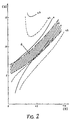
- Fig. 2 where the base curve is plotted on the vertical axis and the power of a lens having a refractive index of 1.50 on the horizontal axis.
- This graph shows the astigmatism produced when the ophthalmic lens is actually used and an object located 30° to the optical axis is viewed.
- the solid lines indicate the astigmatism produced when a distant object is viewed.
- the numerical values put beside the lines indicate the amounts of astigmatism.
- Lines indicating astigmatism of 0.3 D are shown on opposite sides of a line indicating the absence of astigmatism, i.e., 0 D.
- the broken lines indicate the astigmatism produced when an object located at a short distance of 30 cm is viewed.
- the optimum base curve giving zero astigmatism differs between when a remote object is viewed and when a close object is viewed. Accordingly, the base curve a in the hatched region is generally adopted so as to be able to view remote objects and close objects alike.
- Lenses which have positive powers and are principally used for far-sighted persons and presbyopic persons have some disadvantages.
- lenses having larger powers have a larger thickness at their center.
- a lens having a base curve having larger curvatures must be employed, and the convex surface protrudes more. This is unfavorable from an aesthetical point of view.
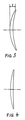
- Fig. 3 is a cross section of one example of such a lens.
- the illustrated lens has a power of +3 D and a diameter of 72 mm.
- the lens is a generally used plastic lens having a refractive index of 1.50.
- the base curve is 7.5 D, and the thickness at each edge is 1.0 mm. In this example, the thickness at the center of the lens is 5.3 mm.
- the amount 1 by which the convex surface of the lens protrudes from the edges of the lens is 10.6 mm. If ophthalmic lens are fabricated from lenses of this construction, then the lenses are considerably thick and unsightly. One conceivable method of solving this problem is to reduce the base curve.
- Fig. 4 shows a lens which is similar to the lens shown in Fig.
- the base curve is 4.0 D.
- the thickness at the center of this lens is 4.9 mm, which is less than the thickness of the lens shown in Fig. 3 by 0.4 mm.
- the amount of protrusion is 5.3 mm, which is half of the amount of the lens shown in Fig. 3.
- the base curve is determined from the optical performance as mentioned above. As shown in Figs. 5 and 6, the base curve of 4.0 D severely deteriorates the optical performance.
- Figs. 5 and 6 show the astigmatisms produced in the field of view when a lens having a base curve of 7.5 D and a lens having a base curve of 4.0 D are respectively used.
- the vertical axis indicates the angle of the field of view in degrees
- the horizontal axis represents the astigmatism in diopters, measured based on the refractive power of the sagital direction.
- the astigmatisms occurring in fields of view when an infinitely remote object ( ⁇ ), an object at a distance of 1 m, and an object at a distance of 0.3 m are viewed are shown.
- JP-B-15,248/1985 and JP-A-24,112/1983 disclose lenses having large positive powers, the lenses being used for aphakial eyes.
- the lens disclosed in JP-B-15,248/1985 adopts an aspherical surface of revolution based on an aspherical surface of revolution of a tenth-order function of the radius r.
- the lens disclosed in JP-A-24,112/1983 adopts an aspherical plane of revolution based on a quadratic curve. A correcting term is added to it.
- What is common to these conventional aspherical lenses is that the curvature of the meridian decreases substantially monotonously and acceleratingly from the axis of rotation (generally the geometrical center of the lens) toward the edges.
- a lens for an aphakial eye has a strong aspherical surface to make the lens thin and so the diameter of the effective field region is from 30 mm to 40 mm at best on the lens.
- Fig. 1(a) is a cross-sectional view of a half of an ophthalmic lens according to the invention.
- Fig. 1(b) shows the manner in which the curvature varies as a meridian goes from the center toward the edge.
- Fig. 1(c) shows the manner in which the amount of astigmatism varies.
- This lens is formed by applying the present invention to the lens which is shown in Fig. 4 and has a power of +3.0 D and a base curve of 4.0 D.
- the lens has a front refractive surface 1 and a rear refractive surface 2. The lens is symmetrical with respect to an axis 3 .
- the cross section of the prior art spherical lens is indicated by the dot-and dash line 4.
- This cross section is an arc having a curvature corresponding to the base curve.
- the front refractive surface 1 of the novel lens has the same curvature as the front surface of the prior art lens 4 near the axis of rotation, but the curvature of the front surface of the novel lens decreases as the meridian approaches the edge. As a result, the front surface is located ahead of the arc of the base curve at the edge.
- Fig. 1(b) shows the manner in which the curvature varies on the meridian. In the graph of Fig.
- the curvature of the meridian gradually decreases at a rate which increases as the meridian goes away from the axis of symmetry.
- the decreasing rate begins to drop in the region between the distance of 15 mm and the distance of 20 mm. After a distance of 35 mm has been reached, the rate is substantially constant, or the curvature begins to increase slightly. This is now discussed further mathematically.
- the curvature be a function C(r) of the distance r from the axis of symmetry.
- the first-order derivative dC/dr starts from 0 on the axis of symmetry and decreases gradually as the meridian goes away from the axis.
- the derivative assumes its minimum value at a distance of 15 to 20 mm and then it increases.
- the front refractive surface takes the form shown in Fig. 1(a). Consequently, the thickness at the center can be reduced as compared with the thickness of the prior art lens.
- the protrusion of the front refractive surface can be reduced.
- the thickness at the center is 4.3 mm, and the amount of protrusion is 4.7 mm. That is a reduction of 0.6 mm in the thickness at the center and a reduction of 5.9 mm in the amount of protrusion have been achieved as compared with the prior art spherical lens shown in Fig. 3.
- the novel lens is made much thinner and flatter than the prior art lens.
- a large amount of astigmatism remains, though the base curve is reduced to 4.0 D, as shown in Fig. 6.
- the amount of astigmatism is reduced greatly as shown in Fig. 1(c).
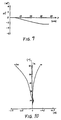
- Figs. 7 and 8 Another ophthalmic lens according to the invention is next described by referring to Figs. 7 and 8.
- This lens has a power of +3.0 D and a base curve of 4.0 D in the same way as the lens already described in connection with Figs. 1(a)-1(c).
- Fig. 7 shows the deviation ⁇ C of the curvature on a meridian. Values of the deviation are listed in Table 2.
- the curvature does not change at all in the region between the center and the distance of 5 mm. That is, the central portion having a radius of 5 mm is a spherical surface. In the region beginning with the end of this spherical portion and ending with the edge, the curvature changes in the same way as the lens described already in conjunction with Figs. 1(a)-1(c). Thus, as shown in Fig. 8, the astigmatism increases in the central spherical portion due to reductions in the base curve. Outside of this portion, the astigmatism is reduced by making the surface aspherical, in the same way as with the previous, first example.
- the base curve and the size of the central spherical portion are so adjusted that the amount of increase in the astigmatism in the central portion is restricted to 0.1 to 0:15 D. This permits the lens to be used without hindrance to the vision.
- the thickness at the center is 4.4 mm, and the amount of protrusion is 4,8 mm.
- the second example has the following advantages over the first example.
- stable results are obtained.
- the power of the lens of the first example is measured on the optical axis (usually coincident with the axis of symmetry) with a lens meter, if the position at which the measurement is made deviates from the correct position, then the power will not be correctly measured or unwanted astigmatic aberrations will be introduced, because the lens is totally aspherical, i.e., has no spherical surface at the center.
- the provision of a spherical surface at the center solves these problems.
- One who compares Fig. 1(c) with Fig. 8 may wonder if the situation is opposite.
- a request for decentration can be fulfilled in the same way as an ordinary lens having a spherical front refractive surface.
- the central spherical portion produces a given power more stably than a lens having a totally aspherical surface. If the lens is decentered within this range, then the desired power can be derived stably, unlike a lens having a totally aspherical surface.
- the central spherical portion be at least 3 mm in radius, preferably more than 5 mm, because the opening In a normally used lens meter is 5 to 10 mm in diameter.
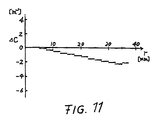
- FIG. 9 shows the deviation ⁇ C of the curvature on a meridian. Values of the deviation are listed in Table 3.
- the thinness at the center is 3.7 mm, and the amount of protrusion is 3.9 mm.
- the thickness is smaller by 1.6 mm (30%) and the amount of protrusion is smaller by 6.7 mm (63%) than those of the conventional spherical lens shown in Fig. 3. Since the material of the lens has a higher refractive index, the thickness at the center and the amount of protrusion are reduced by 0.7 mm and 0.9 mm, respectively, as compared with the second example.
- the astigmatism is shown in Fig. 10 and exhibits good characteristics similarly to the second example shown in Fig. 8.
- these three lenses are designed so that the astigmatism produced when an object located at a distance of 1 m is viewed is reduced substantially down to zero, i.e., the lenses are designed for intermediate vision.
- the lenses can be so designed that the astigmatism occurring when a remote object is viewed is fully eliminated, i.e., the lenses are designed for remote vision.
- the lenses can be designed in such a way that the astigmatism produced when an object located at a short distance of about 30 cm is viewed is removed, i.e., the lenses are designed for close vision. In any case, the same inventive theory is utilized.
- a lens designed for remote vision the curvature is changed to a greater extent than in the above-described examples. Conversely, in a lens designed for close vision, the curvature is changed to a lesser extent.
- the present inventor has confirmed that in a lens designed for remote vision, when the lens is actually used and a remote object is viewed, the lateral portions are somewhat insufficiently corrected as compared with the desired power, i.e., the power on the optical axis. Conversely, in a lens designed for close vision, when a remote object is viewed, the lateral portions are somewhat excessively corrected.
- lenses are preferably designed for intermediate vision to view an object at a distance of about 1 m.
- the novel ophthalmic lens having a positive power has a reduced thickness at the center and a less protruding front refractive surface.
- the optical performance is improved.
- the curvature of a meridian of the prior art aspherical lens changes monotonously and acceleratingly toward the edge.
- the discovered effective method consists in once reducing the first-order derivative of the curvature C(r) as the meridian goes away from the axis of symmetry of the lens and then increasing the derivative.
- the aspherical shape whose radius of curvature changes as described above is combined with a low base curve that is not adopted for an ordinary spherical lens because of the optical performance, to thereby realize an ophthalmic lens which is excellent in optical performance, has a small thickness at its center, is flat, and well-shaped.
- the base curve is the curvature near the axis of symmetry.
- the base curve is made low such that the following relation is satisfied: (n - 1) x ⁇ o ⁇ 0.5 x S + 5 where n is the refractive index of the material of the lens, ⁇ o is the curvature near the axis of rotation, i.e., the curvature of the base curve, and S is the equivalent spherical power (in diopters).
- a material having a high refractive index is combined with the above-described aspherical shape. As a result, greater merits are obtained.
- refractive indices exceeding 1.55 are called medium refractive indices or high refractive indices. Normal refractive index is 1.50.
- the spherical portion formed in the center stabilizes the power of the lens. Also, the novel lens is easy to machine. Further, the lens can be decentered.
- the curvature of the front refractive surface changes continuously. It is to be understood that changes and modifications can be made thereto.
- the curvature may change in a stepwise fashion as the meridian goes away from the axis of rotation. Also, the curvature may change subtly, as long as the radius of curvature is varied similarly to the above-described examples of the invention.
Landscapes
- Health & Medical Sciences (AREA)
- Ophthalmology & Optometry (AREA)
- Physics & Mathematics (AREA)
- General Health & Medical Sciences (AREA)
- General Physics & Mathematics (AREA)
- Optics & Photonics (AREA)
- Eyeglasses (AREA)
- Lenses (AREA)
Description
- The present invention relates to the shape of the front convex surface of an aspherical ophthalmic lens and, more particularly, to the shape of an aspherical ophthalmic lens having a positive power.
- Generally, the front convex surfaces of ophthalmic lenses for correcting eyes, refractive error have been made spherical for easiness of machining. Such a lens is called a spherical lens. Generally, the refractive power of a lens is represented in diopters, abbreviated D. The refractive power of a surface of a lens is defined as
- Lenses which have positive powers and are principally used for far-sighted persons and presbyopic persons have some disadvantages. In particular, lenses having larger powers have a larger thickness at their center. As the degree of the farsightedness or presbyopia increases, a lens having a base curve having larger curvatures must be employed, and the convex surface protrudes more. This is unfavorable from an aesthetical point of view.
- Fig. 3 is a cross section of one example of such a lens. The illustrated lens has a power of +3 D and a diameter of 72 mm. The lens is a generally used plastic lens having a refractive index of 1.50. The base curve is 7.5 D, and the thickness at each edge is 1.0 mm. In this example, the thickness at the center of the lens is 5.3 mm. The amount 1 by which the convex surface of the lens protrudes from the edges of the lens is 10.6 mm. If ophthalmic lens are fabricated from lenses of this construction, then the lenses are considerably thick and unsightly. One conceivable method of solving this problem is to reduce the base curve. Fig. 4 shows a lens which is similar to the lens shown in Fig. 3 except that the base curve is 4.0 D. The thickness at the center of this lens is 4.9 mm, which is less than the thickness of the lens shown in Fig. 3 by 0.4 mm. Also, the amount of protrusion is 5.3 mm, which is half of the amount of the lens shown in Fig. 3. However, the base curve is determined from the optical performance as mentioned above. As shown in Figs. 5 and 6, the base curve of 4.0 D severely deteriorates the optical performance. Figs. 5 and 6 show the astigmatisms produced in the field of view when a lens having a base curve of 7.5 D and a lens having a base curve of 4.0 D are respectively used. The vertical axis indicates the angle of the field of view in degrees, while the horizontal axis represents the astigmatism in diopters, measured based on the refractive power of the sagital direction. The astigmatisms occurring in fields of view when an infinitely remote object (∞), an object at a distance of 1 m, and an object at a distance of 0.3 m are viewed are shown.
- To solve the above-described disadvantage, some lenses having aspherical front refractive surfaces have been proposed, as disclosed in JP-A-136,644/1977, JP-B-15,248/1985 (US-A-4,181,409), and JP-A-24,112/1983 (US-A-4,504,128). In the lens disclosed in JP-A-136,644/1977, a meridian is formed by a quadratic curve such as an ellipse, parabola, or hyperbola. The front refractive surface is formed by an aspherical surface that is created by rotating the meridian. A lot of lenses of this type has been suggested. JP-B-15,248/1985 and JP-A-24,112/1983 disclose lenses having large positive powers, the lenses being used for aphakial eyes. The lens disclosed in JP-B-15,248/1985 adopts an aspherical surface of revolution based on an aspherical surface of revolution of a tenth-order function of the radius r. The lens disclosed in JP-A-24,112/1983 adopts an aspherical plane of revolution based on a quadratic curve. A correcting term is added to it. What is common to these conventional aspherical lenses is that the curvature of the meridian decreases substantially monotonously and acceleratingly from the axis of rotation (generally the geometrical center of the lens) toward the edges. As a result, the power of the lens is much lower in the peripheral portions than in the center. This narrows the effective field region suitable for the condition of the user's eye. Especially, a lens for an aphakial eye has a strong aspherical surface to make the lens thin and so the diameter of the effective field region is from 30 mm to 40 mm at best on the lens.
- It is an object of the present invention to provide an ophthalmic lens which has a positive power and is used for farsightedness and presbyopia but is free of the foregoing problems and which is excellent in optical performance, thin, and well-shaped.
- The above object is achieved by an ophthalmic lens as claimed in claim 1.
- Specific embodiments of the invention are claimed in the dependent claims.
- Other objects and features of the invention will be described in detail below in connection with the drawings, which illustrate specific embodiments only and wherein
- Fig. 1(a)
- is a cross-sectional view of an ophthalmic lens according to the invention, taken along a meridian;
- Fig. 1(b)
- is a graph in which the deviation of the curvature of the meridian of the lens shown in Fig. 1 from the base curve is plotted against the distance from the axis of symmetry;
- Fig. 1(c)
- is a graph in which the angle of field of view is plotted against the amount of astigmatism;
- Fig. 2
- is a graph showing the astigmatism produced at an angle of field of view of 30° by the combination of the power of a conventional spherical lens and the base curve;
- Fig. 3
- is a cross-sectional view of a known spherical lens having a power of +3.0 D and a base curve of 7.5 D;
- Fig. 4
- is a cross-sectional view of another known spherical lens having a power of +3.0 D and a base curve of 4.0 D;
- Fig. 5
- is a graph in which the angle of the field of view of the known lens shown in Fig. 3 is plotted against the amount of astigmatism;
- Fig. 6
- is a graph in which the angle of the field of view of the known lens shown in Fig. 4 is plotted against the amount of astigmatism;
- Fig. 7
- is a graph showing the changes in the curvature of a meridian of another ophthalmic lens according to the invention;
- Fig. 8
- is a graph in which the angle of the field of view is plotted against the amount of astigmatism produced by the lens described just above;
- Fig. 9
- is a graph showing the changes in the curvature of a meridian of a further ophthalmic lens according to the invention;
- Fig. 10
- is a graph in which the angle of the field of view is plotted against the amount of astigmatism produced by the lens described just above; and
- Fig. 11
- is a graph showing the changes in the curvature of a meridian of a still other ophthalmic lens according to the invention.
- Fig. 1(a) is a cross-sectional view of a half of an ophthalmic lens according to the invention. Fig. 1(b) shows the manner in which the curvature varies as a meridian goes from the center toward the edge. Fig. 1(c) shows the manner in which the amount of astigmatism varies. This lens is formed by applying the present invention to the lens which is shown in Fig. 4 and has a power of +3.0 D and a base curve of 4.0 D. In Fig. 1(a), the lens has a front refractive surface 1 and a rear
refractive surface 2. The lens is symmetrical with respect to anaxis 3 . The cross section of the prior art spherical lens is indicated by the dot-anddash line 4. This cross section is an arc having a curvature corresponding to the base curve. The front refractive surface 1 of the novel lens has the same curvature as the front surface of theprior art lens 4 near the axis of rotation, but the curvature of the front surface of the novel lens decreases as the meridian approaches the edge. As a result, the front surface is located ahead of the arc of the base curve at the edge. Fig. 1(b) shows the manner in which the curvature varies on the meridian. In the graph of Fig. 1 (b), the deviation of the curvature from the base curve is plotted on the vertical axis and the distance from the axis of symmetry on the horizontal axis. Values of the deviation ΔC of the curvature are listed in Table 1.r (mm) Δ C (m-1) 0.0 0.00 2.5 -0.04 5.0 -0.15 7.5 -0.34 10.0 -0.57 12.5 -0.84 15.0 -1.12 17.5 -1.41 20.0 -1.68 22.5 -1.94 25.0 -2.16 27.5 -2.36 30.0 -2.52 32.5 -2.66 35.0 -2.74 37.5 -2.73 r (mm) Δ C (m-1) 0.0 0.00 2.5 0.00 5.0 0.00 7.5 -0.27 10.0 -0.50 12.5 -0.77 15.0 -1.06 17.5 -1.35 20.0 -1.63 22.5 -1.89 25.0 -2.12 27.5 -2.32 30.0 -2.49 32.5 -2.62 35.0 -2.71 37.5 -2.70 - As shown in Fig. 1 (b), the curvature of the meridian gradually decreases at a rate which increases as the meridian goes away from the axis of symmetry. The decreasing rate begins to drop in the region between the distance of 15 mm and the distance of 20 mm. After a distance of 35 mm has been reached, the rate is substantially constant, or the curvature begins to increase slightly. This is now discussed further mathematically. Let the curvature be a function C(r) of the distance r from the axis of symmetry. The first-order derivative dC/dr starts from 0 on the axis of symmetry and decreases gradually as the meridian goes away from the axis. The derivative assumes its minimum value at a distance of 15 to 20 mm and then it increases. By changing the curvature in this way, the front refractive surface takes the form shown in Fig. 1(a). Consequently, the thickness at the center can be reduced as compared with the thickness of the prior art lens. At the same time, the protrusion of the front refractive surface can be reduced. In this specific example, the thickness at the center is 4.3 mm, and the amount of protrusion is 4.7 mm. That is a reduction of 0.6 mm in the thickness at the center and a reduction of 5.9 mm in the amount of protrusion have been achieved as compared with the prior art spherical lens shown in Fig. 3. Hence, the novel lens is made much thinner and flatter than the prior art lens. In the spherical lens, a large amount of astigmatism remains, though the base curve is reduced to 4.0 D, as shown in Fig. 6. In the novel lens, the amount of astigmatism is reduced greatly as shown in Fig. 1(c).
- Another ophthalmic lens according to the invention is next described by referring to Figs. 7 and 8. This lens has a power of +3.0 D and a base curve of 4.0 D in the same way as the lens already described in connection with Figs. 1(a)-1(c). Fig. 7 shows the deviation ΔC of the curvature on a meridian. Values of the deviation are listed in Table 2.
- As can be seen from Table 2, in this example, the curvature does not change at all in the region between the center and the distance of 5 mm. That is, the central portion having a radius of 5 mm is a spherical surface. In the region beginning with the end of this spherical portion and ending with the edge, the curvature changes in the same way as the lens described already in conjunction with Figs. 1(a)-1(c). Thus, as shown in Fig. 8, the astigmatism increases in the central spherical portion due to reductions in the base curve. Outside of this portion, the astigmatism is reduced by making the surface aspherical, in the same way as with the previous, first example. The base curve and the size of the central spherical portion are so adjusted that the amount of increase in the astigmatism in the central portion is restricted to 0.1 to 0:15 D. This permits the lens to be used without hindrance to the vision. At this time, the thickness at the center is 4.4 mm, and the amount of protrusion is 4,8 mm. These values are somewhat inferior to the values obtained by the example described first, but this second example still realizes a great reduction in the thickness and provides a flattened lens.
- The second example has the following advantages over the first example. When the power of the lens is measured, stable results are obtained. Specifically, when the power of the lens of the first example is measured on the optical axis (usually coincident with the axis of symmetry) with a lens meter, if the position at which the measurement is made deviates from the correct position, then the power will not be correctly measured or unwanted astigmatic aberrations will be introduced, because the lens is totally aspherical, i.e., has no spherical surface at the center. The provision of a spherical surface at the center solves these problems. One who compares Fig. 1(c) with Fig. 8 may wonder if the situation is opposite. However, these two figures show the astigmatism occurring in the region between the center and the edge when the lens is actually used. When the power is measured with a lens meter, the light rays pass at angles different from the actual use and, therefore, it seems as if the situation were switched between Fig. 1(c) and Fig. 8.
- A request for decentration can be fulfilled in the same way as an ordinary lens having a spherical front refractive surface. In particular, the central spherical portion produces a given power more stably than a lens having a totally aspherical surface. If the lens is decentered within this range, then the desired power can be derived stably, unlike a lens having a totally aspherical surface.
- In order to obtain these advantages, it Is necessary that the central spherical portion be at least 3 mm in radius, preferably more than 5 mm, because the opening In a normally used lens meter is 5 to 10 mm in diameter.
- A further ophthalmic lens is next described by referring to Fig. 9. This lens has a power of +3.0 D, a base curve of 4.0 D, and a diameter of 72 mm, in the same way as the second example. However, this third example has a refractive index of 1.60 and an Abbe number of 35, which are different from those of the first example. Fig. 9 shows the deviation ΔC of the curvature on a meridian. Values of the deviation are listed in Table 3.
r (mm) Δ C (m-1) 0.0 0.00 2.5 0.00 5.0 0.00 7.5 -0.24 10.0 -0.49 12.5 -0.75 15.0 -1.02 17.5 -1.29 20.0 -1.55 22.5 -1.79 25.0 -2.01 27.5 -2.19 30.0 -2.35 32.5 -2.48 35.0 -2.58 37.5 -2.55 - In this example the thinness at the center is 3.7 mm, and the amount of protrusion is 3.9 mm. The thickness is smaller by 1.6 mm (30%) and the amount of protrusion is smaller by 6.7 mm (63%) than those of the conventional spherical lens shown in Fig. 3. Since the material of the lens has a higher refractive index, the thickness at the center and the amount of protrusion are reduced by 0.7 mm and 0.9 mm, respectively, as compared with the second example.
- The astigmatism is shown in Fig. 10 and exhibits good characteristics similarly to the second example shown in Fig. 8.
- As can be seen from the graphs of Figs. 1(c), 8, and 10 about astigmatism, these three lenses are designed so that the astigmatism produced when an object located at a distance of 1 m is viewed is reduced substantially down to zero, i.e., the lenses are designed for intermediate vision. Instead, the lenses can be so designed that the astigmatism occurring when a remote object is viewed is fully eliminated, i.e., the lenses are designed for remote vision. Also, the lenses can be designed in such a way that the astigmatism produced when an object located at a short distance of about 30 cm is viewed is removed, i.e., the lenses are designed for close vision. In any case, the same inventive theory is utilized. In a lens designed for remote vision, the curvature is changed to a greater extent than in the above-described examples. Conversely, in a lens designed for close vision, the curvature is changed to a lesser extent. The present inventor has confirmed that in a lens designed for remote vision, when the lens is actually used and a remote object is viewed, the lateral portions are somewhat insufficiently corrected as compared with the desired power, i.e., the power on the optical axis. Conversely, in a lens designed for close vision, when a remote object is viewed, the lateral portions are somewhat excessively corrected. For general use, lenses are preferably designed for intermediate vision to view an object at a distance of about 1 m.
- As described thus far, the novel ophthalmic lens having a positive power has a reduced thickness at the center and a less protruding front refractive surface. Also, the optical performance is improved. With respect to the improvement of the optical performance, the curvature of a meridian of the prior art aspherical lens changes monotonously and acceleratingly toward the edge. The discovered effective method consists in once reducing the first-order derivative of the curvature C(r) as the meridian goes away from the axis of symmetry of the lens and then increasing the derivative. By changing the curvature as described above, astigmatism can be controlled well over the whole range of the lens irrespective of the distance to the viewed object. Since the power of the lens does not drop greatly in the peripheral portions, a wide field of view is secured.
- The aspherical shape whose radius of curvature changes as described above is combined with a low base curve that is not adopted for an ordinary spherical lens because of the optical performance, to thereby realize an ophthalmic lens which is excellent in optical performance, has a small thickness at its center, is flat, and well-shaped. In the present invention, the base curve is the curvature near the axis of symmetry. The base curve is made low such that the following relation is satisfied:
- As described in the third example, a material having a high refractive index is combined with the above-described aspherical shape. As a result, greater merits are obtained. In the field of plastic ophthalmic lenses, refractive indices exceeding 1.55 are called medium refractive indices or high refractive indices. Normal refractive index is 1.50.
- Generally, materials having high refractive indices have small Abbe numbers. In the case of plastic materials having refractive indices exceeding 1.55, the Abbe numbers are under approximately 40. Therefore, where an object is viewed through a peripheral portion of the lens, light is dispersed by the prismatic action of the lens, resulting in Colored fringes surrounding the image. This defect is called chromatic aberration. However, in a lens having an aspherical surface according to the invention, the wedge-like portion formed around the edge by the front refractive surface as shown in Fig. 1(a) is smaller than the wedge-like portion of a spherical lens. That is, the prismatic action decreases to thereby reduce chromatic aberrations.
- The spherical portion formed in the center stabilizes the power of the lens. Also, the novel lens is easy to machine. Further, the lens can be decentered.
- In the first and second examples described above, the curvature of the front refractive surface changes continuously. It is to be understood that changes and modifications can be made thereto. For example, as shown in Fig. 11, the curvature may change in a stepwise fashion as the meridian goes away from the axis of rotation. Also, the curvature may change subtly, as long as the radius of curvature is varied similarly to the above-described examples of the invention.
Claims (4)
- An aspherical positive ophthalmic lens having a front refractive surface (1) and a rear refractive surface (2),the front refractive surface being aspherical in shape and being symmetrical with respect to an axis of rotation passing through the apex of said surface,the curvature of an arbitrary meridian passing through the apex of the front refractive surface being a function C(r) of the distance r from the apex,
wherein the first-order derivative dC/dr of the function C(r) varies such that it once decreases as the meridian goes away from said apex, assumes a minimum within a region of a distance r from 15 to 20 mm and then increases,
characterized in that the first-order derivative dC/dr of the function C(r) is zero at the apex and that the curvature begins to increase after a distance r of 35 mm has been reached, and
that the lens has a power of +3 diopters and a base curve of 4 diopters. - The lens of claim 1, wherein the curvature of said front refractive surface (1) is kept constant as the meridian goes at least 3 mm, preferably more than 5 mm, in each direction from the apex and then the curvature decreases.
- The lens of claim 1 or 2, wherein the following relation is satisfied:
- The lens of any one of claims 1 to 3, wherein the refractive index of the material of the lens is equal to or in excess of 1.55 and the Abbe number is equal to or less than 40.
Applications Claiming Priority (9)
| Application Number | Priority Date | Filing Date | Title |
|---|---|---|---|
| JP1217589 | 1989-01-21 | ||
| JP1217589 | 1989-01-21 | ||
| JP12175/89 | 1989-01-21 | ||
| JP3755989 | 1989-02-17 | ||
| JP37559/89 | 1989-02-17 | ||
| JP3755989 | 1989-02-17 | ||
| JP327613/89 | 1989-12-18 | ||
| JP32761389 | 1989-12-18 | ||
| JP01327613A JP3038745B2 (en) | 1989-01-21 | 1989-12-18 | Eyeglass lens |
Publications (4)
| Publication Number | Publication Date |
|---|---|
| EP0379976A2 EP0379976A2 (en) | 1990-08-01 |
| EP0379976A3 EP0379976A3 (en) | 1991-05-29 |
| EP0379976B1 EP0379976B1 (en) | 1994-12-07 |
| EP0379976B2 true EP0379976B2 (en) | 2000-02-16 |
Family
ID=27279732
Family Applications (1)
| Application Number | Title | Priority Date | Filing Date |
|---|---|---|---|
| EP90101015A Expired - Lifetime EP0379976B2 (en) | 1989-01-21 | 1990-01-18 | Aspherical ophthalmic lens |
Country Status (3)
| Country | Link |
|---|---|
| US (1) | US5050980A (en) |
| EP (1) | EP0379976B2 (en) |
| DE (1) | DE69014656T2 (en) |
Families Citing this family (14)
| Publication number | Priority date | Publication date | Assignee | Title |
|---|---|---|---|---|
| JPH085967A (en) * | 1994-06-23 | 1996-01-12 | Nikon Corp | Aspherical spectacle lens |
| DE19540186A1 (en) * | 1995-10-28 | 1997-04-30 | Rodenstock Optik G | Single vision glasses with two aspherical surfaces |
| US5825454A (en) * | 1996-01-16 | 1998-10-20 | Hoya Corporation | Aspherical spectacle lens |
| JPH1078566A (en) * | 1996-09-05 | 1998-03-24 | Asahi Optical Co Ltd | Spectacle lens |
| US6012813A (en) * | 1997-06-19 | 2000-01-11 | Hoya Corporation | Aspherical spectacle lens |
| US20020008844A1 (en) * | 1999-10-26 | 2002-01-24 | Copeland Victor L. | Optically superior decentered over-the-counter sunglasses |
| US6036315A (en) * | 1998-03-18 | 2000-03-14 | Copeland; Victor L. | Optically superior decentered over-the-counter sunglasses |
| EP0964285A1 (en) * | 1998-06-10 | 1999-12-15 | Nikon Corporation | Aspheric ophthalmic lens |
| JP3845251B2 (en) | 2000-07-05 | 2006-11-15 | ペンタックス株式会社 | Manufacturing method and supply method of spectacle lens |
| JP3851495B2 (en) | 2000-07-07 | 2006-11-29 | ペンタックス株式会社 | Eyeglass lens design method, manufacturing method, and eyeglass lens |
| JP3892702B2 (en) * | 2000-10-17 | 2007-03-14 | ペンタックス株式会社 | Aspheric spectacle lens |
| US6955430B2 (en) * | 2001-12-11 | 2005-10-18 | Pratt Steven G | Blue blocking lens |
| US7255435B2 (en) * | 2001-12-11 | 2007-08-14 | Pratt Steven G | Blue blocking tens |
| CN113253482B (en) * | 2021-06-01 | 2022-05-13 | 苏州科技大学 | Two-stage meridian design method for progressive multi-focus spectacle lens |
Family Cites Families (7)
| Publication number | Priority date | Publication date | Assignee | Title |
|---|---|---|---|---|
| US3960442A (en) * | 1974-08-05 | 1976-06-01 | American Optical Corporation | Ophthalmic lens series |
| JPS52136644A (en) * | 1976-05-11 | 1977-11-15 | Seiko Epson Corp | Lens for spectacles |
| US4181409A (en) * | 1978-10-16 | 1980-01-01 | American Optical Corporation | Aspheric lens series |
| FR2440011A1 (en) * | 1978-10-24 | 1980-05-23 | Essilor Int | OPHTHALMIC LENS, ESPECIALLY FOR FORT MYOPE |
| DE3016936C2 (en) * | 1980-05-02 | 1983-12-01 | Fa. Carl Zeiss, 7920 Heidenheim | Spectacle lens with astigmatic power |
| AT387468B (en) * | 1981-07-08 | 1989-01-25 | Rodenstock Optik G | EYE GLASS WITH HIGH POSITIVE REFRESHING VALUE |
| DE3343891C2 (en) * | 1983-12-05 | 1986-06-05 | Optische Werke G. Rodenstock, 8000 München | Multifocal lens with a high positive refractive index |
-
1990
- 1990-01-18 US US07/466,818 patent/US5050980A/en not_active Expired - Lifetime
- 1990-01-18 DE DE69014656T patent/DE69014656T2/en not_active Expired - Fee Related
- 1990-01-18 EP EP90101015A patent/EP0379976B2/en not_active Expired - Lifetime
Also Published As
| Publication number | Publication date |
|---|---|
| US5050980A (en) | 1991-09-24 |
| EP0379976A2 (en) | 1990-08-01 |
| DE69014656D1 (en) | 1995-01-19 |
| EP0379976B1 (en) | 1994-12-07 |
| DE69014656T2 (en) | 1995-05-18 |
| EP0379976A3 (en) | 1991-05-29 |
Similar Documents
| Publication | Publication Date | Title |
|---|---|---|
| US5050979A (en) | Eyeglass lens | |
| US4062629A (en) | Progressive power ophthalmic lens having a plurality of viewing zone with discontinuous power variations therebetween | |
| US3960442A (en) | Ophthalmic lens series | |
| US6019470A (en) | Progressive multifocal lens and manufacturing method of eyeglass lens and progressive multifocal lens | |
| EP0379976B2 (en) | Aspherical ophthalmic lens | |
| US4561736A (en) | Eyeglass lenses for persons suffering from severe ametropia | |
| US5173723A (en) | Aspheric ophthalmic accommodating lens design for intraocular lens and contact lens | |
| US4056311A (en) | Progressive power ophthalmic lens having a plurality of viewing zones with non-discontinuous variations therebetween | |
| US7134752B2 (en) | Shaped non-corrective eyewear lenses and methods for providing same | |
| US4055379A (en) | Multifocal lens | |
| US4504128A (en) | Spectacle lens with high positive refractive power | |
| JPS6015248B2 (en) | Aspheric lens series | |
| EP0461624B1 (en) | Spectacle lens | |
| US5550600A (en) | Ophthalmic lens having a negative refractive power | |
| US5235357A (en) | Spectacle lenses having an inside-out conicoidal front surface and method for forming same | |
| US5353072A (en) | Aspherical spectacle lens | |
| US5455642A (en) | Progressive power lens | |
| US4289387A (en) | Ophthalmic spectacle lenses having a hyperbolic surface | |
| JPH0812339B2 (en) | Eyeglass lens | |
| JP2002520674A (en) | Optical lens | |
| US5083859A (en) | Aspheric lenses | |
| US5610670A (en) | Opthalmic lens having a positive refractive power | |
| JP3038745B2 (en) | Eyeglass lens | |
| JP2002372689A (en) | Progressive power lens and eyeglass lens | |
| JPS6061719A (en) | Progressive multifocus lens |
Legal Events
| Date | Code | Title | Description |
|---|---|---|---|
| PUAI | Public reference made under article 153(3) epc to a published international application that has entered the european phase |
Free format text: ORIGINAL CODE: 0009012 |
|
| AK | Designated contracting states |
Kind code of ref document: A2 Designated state(s): DE FR GB |
|
| PUAL | Search report despatched |
Free format text: ORIGINAL CODE: 0009013 |
|
| AK | Designated contracting states |
Kind code of ref document: A3 Designated state(s): DE FR GB |
|
| 17P | Request for examination filed |
Effective date: 19911108 |
|
| 17Q | First examination report despatched |
Effective date: 19930827 |
|
| GRAA | (expected) grant |
Free format text: ORIGINAL CODE: 0009210 |
|
| AK | Designated contracting states |
Kind code of ref document: B1 Designated state(s): DE FR GB |
|
| REF | Corresponds to: |
Ref document number: 69014656 Country of ref document: DE Date of ref document: 19950119 |
|
| ET | Fr: translation filed | ||
| PLBI | Opposition filed |
Free format text: ORIGINAL CODE: 0009260 |
|
| PLBI | Opposition filed |
Free format text: ORIGINAL CODE: 0009260 |
|
| 26 | Opposition filed |
Opponent name: ESSILOR INTERNATIONAL Effective date: 19950904 |
|
| 26 | Opposition filed |
Opponent name: ESSILOR INTERNATIONAL Effective date: 19950904 |
|
| PLBF | Reply of patent proprietor to notice(s) of opposition |
Free format text: ORIGINAL CODE: EPIDOS OBSO |
|
| PLBF | Reply of patent proprietor to notice(s) of opposition |
Free format text: ORIGINAL CODE: EPIDOS OBSO |
|
| PLAW | Interlocutory decision in opposition |
Free format text: ORIGINAL CODE: EPIDOS IDOP |
|
| PLAW | Interlocutory decision in opposition |
Free format text: ORIGINAL CODE: EPIDOS IDOP |
|
| PUAH | Patent maintained in amended form |
Free format text: ORIGINAL CODE: 0009272 |
|
| STAA | Information on the status of an ep patent application or granted ep patent |
Free format text: STATUS: PATENT MAINTAINED AS AMENDED |
|
| 27A | Patent maintained in amended form |
Effective date: 20000216 |
|
| AK | Designated contracting states |
Kind code of ref document: B2 Designated state(s): DE FR GB |
|
| ET3 | Fr: translation filed ** decision concerning opposition | ||
| REG | Reference to a national code |
Ref country code: GB Ref legal event code: IF02 |
|
| PGFP | Annual fee paid to national office [announced via postgrant information from national office to epo] |
Ref country code: GB Payment date: 20080116 Year of fee payment: 19 Ref country code: DE Payment date: 20080110 Year of fee payment: 19 |
|
| PLAB | Opposition data, opponent's data or that of the opponent's representative modified |
Free format text: ORIGINAL CODE: 0009299OPPO |
|
| PGFP | Annual fee paid to national office [announced via postgrant information from national office to epo] |
Ref country code: FR Payment date: 20080108 Year of fee payment: 19 |
|
| PLAB | Opposition data, opponent's data or that of the opponent's representative modified |
Free format text: ORIGINAL CODE: 0009299OPPO |
|
| GBPC | Gb: european patent ceased through non-payment of renewal fee |
Effective date: 20090118 |
|
| PG25 | Lapsed in a contracting state [announced via postgrant information from national office to epo] |
Ref country code: DE Free format text: LAPSE BECAUSE OF NON-PAYMENT OF DUE FEES Effective date: 20090801 |
|
| REG | Reference to a national code |
Ref country code: FR Ref legal event code: ST Effective date: 20091030 |
|
| PG25 | Lapsed in a contracting state [announced via postgrant information from national office to epo] |
Ref country code: GB Free format text: LAPSE BECAUSE OF NON-PAYMENT OF DUE FEES Effective date: 20090118 |
|
| PG25 | Lapsed in a contracting state [announced via postgrant information from national office to epo] |
Ref country code: FR Free format text: LAPSE BECAUSE OF NON-PAYMENT OF DUE FEES Effective date: 20090202 |