EP0379319B1 - Fluid homogenization - Google Patents
Fluid homogenization Download PDFInfo
- Publication number
- EP0379319B1 EP0379319B1 EP90300391A EP90300391A EP0379319B1 EP 0379319 B1 EP0379319 B1 EP 0379319B1 EP 90300391 A EP90300391 A EP 90300391A EP 90300391 A EP90300391 A EP 90300391A EP 0379319 B1 EP0379319 B1 EP 0379319B1
- Authority
- EP
- European Patent Office
- Prior art keywords
- vessel
- liquid
- flow
- gas
- piping
- Prior art date
- Legal status (The legal status is an assumption and is not a legal conclusion. Google has not performed a legal analysis and makes no representation as to the accuracy of the status listed.)
- Expired - Lifetime
Links
- 239000012530 fluid Substances 0.000 title claims description 16
- 238000000265 homogenisation Methods 0.000 title description 2
- 239000007788 liquid Substances 0.000 claims abstract description 40
- 238000002156 mixing Methods 0.000 claims abstract description 7
- 239000012071 phase Substances 0.000 claims description 18
- 238000000034 method Methods 0.000 claims description 10
- 230000005484 gravity Effects 0.000 claims description 8
- 239000007791 liquid phase Substances 0.000 claims description 7
- 238000011144 upstream manufacturing Methods 0.000 claims description 3
- 230000001419 dependent effect Effects 0.000 claims 1
- 239000008240 homogeneous mixture Substances 0.000 abstract description 2
- 239000011800 void material Substances 0.000 description 7
- 230000007423 decrease Effects 0.000 description 2
- 239000000203 mixture Substances 0.000 description 2
- 241000237858 Gastropoda Species 0.000 description 1
- 230000033228 biological regulation Effects 0.000 description 1
- 239000000463 material Substances 0.000 description 1
- 238000005192 partition Methods 0.000 description 1
- 238000005086 pumping Methods 0.000 description 1
Images
Classifications
-
- B—PERFORMING OPERATIONS; TRANSPORTING
- B01—PHYSICAL OR CHEMICAL PROCESSES OR APPARATUS IN GENERAL
- B01F—MIXING, e.g. DISSOLVING, EMULSIFYING OR DISPERSING
- B01F23/00—Mixing according to the phases to be mixed, e.g. dispersing or emulsifying
- B01F23/40—Mixing liquids with liquids; Emulsifying
- B01F23/45—Mixing liquids with liquids; Emulsifying using flow mixing
- B01F23/454—Mixing liquids with liquids; Emulsifying using flow mixing by injecting a mixture of liquid and gas
-
- B—PERFORMING OPERATIONS; TRANSPORTING
- B01—PHYSICAL OR CHEMICAL PROCESSES OR APPARATUS IN GENERAL
- B01F—MIXING, e.g. DISSOLVING, EMULSIFYING OR DISPERSING
- B01F23/00—Mixing according to the phases to be mixed, e.g. dispersing or emulsifying
- B01F23/20—Mixing gases with liquids
- B01F23/23—Mixing gases with liquids by introducing gases into liquid media, e.g. for producing aerated liquids
- B01F23/232—Mixing gases with liquids by introducing gases into liquid media, e.g. for producing aerated liquids using flow-mixing means for introducing the gases, e.g. baffles
- B01F23/2326—Mixing gases with liquids by introducing gases into liquid media, e.g. for producing aerated liquids using flow-mixing means for introducing the gases, e.g. baffles adding the flowing main component by suction means, e.g. using an ejector
-
- B—PERFORMING OPERATIONS; TRANSPORTING
- B01—PHYSICAL OR CHEMICAL PROCESSES OR APPARATUS IN GENERAL
- B01F—MIXING, e.g. DISSOLVING, EMULSIFYING OR DISPERSING
- B01F23/00—Mixing according to the phases to be mixed, e.g. dispersing or emulsifying
- B01F23/40—Mixing liquids with liquids; Emulsifying
- B01F23/45—Mixing liquids with liquids; Emulsifying using flow mixing
- B01F23/452—Mixing liquids with liquids; Emulsifying using flow mixing by uniting flows taken from different parts of a receptacle or silo; Sandglass-type mixing
-
- B—PERFORMING OPERATIONS; TRANSPORTING
- B01—PHYSICAL OR CHEMICAL PROCESSES OR APPARATUS IN GENERAL
- B01F—MIXING, e.g. DISSOLVING, EMULSIFYING OR DISPERSING
- B01F25/00—Flow mixers; Mixers for falling materials, e.g. solid particles
- B01F25/30—Injector mixers
- B01F25/31—Injector mixers in conduits or tubes through which the main component flows
- B01F25/312—Injector mixers in conduits or tubes through which the main component flows with Venturi elements; Details thereof
- B01F25/3124—Injector mixers in conduits or tubes through which the main component flows with Venturi elements; Details thereof characterised by the place of introduction of the main flow
- B01F25/31241—Injector mixers in conduits or tubes through which the main component flows with Venturi elements; Details thereof characterised by the place of introduction of the main flow the main flow being injected in the circumferential area of the venturi, creating an aspiration in the central part of the conduit
-
- B—PERFORMING OPERATIONS; TRANSPORTING
- B01—PHYSICAL OR CHEMICAL PROCESSES OR APPARATUS IN GENERAL
- B01F—MIXING, e.g. DISSOLVING, EMULSIFYING OR DISPERSING
- B01F25/00—Flow mixers; Mixers for falling materials, e.g. solid particles
- B01F25/40—Static mixers
- B01F25/44—Mixers in which the components are pressed through slits
- B01F25/441—Mixers in which the components are pressed through slits characterised by the configuration of the surfaces forming the slits
- B01F25/4412—Mixers in which the components are pressed through slits characterised by the configuration of the surfaces forming the slits the slits being formed between opposed planar surfaces, e.g. pushed again each other by springs
-
- B—PERFORMING OPERATIONS; TRANSPORTING
- B01—PHYSICAL OR CHEMICAL PROCESSES OR APPARATUS IN GENERAL
- B01F—MIXING, e.g. DISSOLVING, EMULSIFYING OR DISPERSING
- B01F35/00—Accessories for mixers; Auxiliary operations or auxiliary devices; Parts or details of general application
- B01F35/71—Feed mechanisms
- B01F35/712—Feed mechanisms for feeding fluids
-
- B—PERFORMING OPERATIONS; TRANSPORTING
- B01—PHYSICAL OR CHEMICAL PROCESSES OR APPARATUS IN GENERAL
- B01F—MIXING, e.g. DISSOLVING, EMULSIFYING OR DISPERSING
- B01F23/00—Mixing according to the phases to be mixed, e.g. dispersing or emulsifying
- B01F23/20—Mixing gases with liquids
- B01F23/23—Mixing gases with liquids by introducing gases into liquid media, e.g. for producing aerated liquids
-
- B—PERFORMING OPERATIONS; TRANSPORTING
- B01—PHYSICAL OR CHEMICAL PROCESSES OR APPARATUS IN GENERAL
- B01F—MIXING, e.g. DISSOLVING, EMULSIFYING OR DISPERSING
- B01F23/00—Mixing according to the phases to be mixed, e.g. dispersing or emulsifying
- B01F23/40—Mixing liquids with liquids; Emulsifying
-
- Y—GENERAL TAGGING OF NEW TECHNOLOGICAL DEVELOPMENTS; GENERAL TAGGING OF CROSS-SECTIONAL TECHNOLOGIES SPANNING OVER SEVERAL SECTIONS OF THE IPC; TECHNICAL SUBJECTS COVERED BY FORMER USPC CROSS-REFERENCE ART COLLECTIONS [XRACs] AND DIGESTS
- Y10—TECHNICAL SUBJECTS COVERED BY FORMER USPC
- Y10S—TECHNICAL SUBJECTS COVERED BY FORMER USPC CROSS-REFERENCE ART COLLECTIONS [XRACs] AND DIGESTS
- Y10S261/00—Gas and liquid contact apparatus
- Y10S261/75—Flowing liquid aspirates gas
Definitions
- the invention relates to the homogenization of a liquid and a gas.
- the invention has particular application to the treatment of fluid flows which are multi-phase, in that they comprise both gas and liquid components, but which are by no means uniformly better mixed or homogenized.
- a mixture of gas and oil extracted from an onshore or a subsea well can vary substantially as regards its gas and liquid components. It may comprise slugs of substantially unmixed liquid separated by primarily gaseous portions, as well as portions that are more or less homogeneous. This inconsistency of the nature of the extracted material makes it difficult to handle, in particular by pumping equipment, which could more readily deal with a more homogeneous mixture.
- the invention is consequently concerned with conveniently achieving multi-phase fluid flows which are effectively homogenized and accordingly provides a method of and an apparatus for obtaining a homogenized multi-phase fluid flow in a simple and convenient way. It is known from US-A-4 267 052 to aerate a circulating liquid in a vessel having a bottom mixing rotor at the end of a rotatable hollow shaft having openings to the liquid, and to air above the liquid.
- the shaft includes a venturi nozzle downstream of the liquid opening and a gas tube wherein liquid and gas are mixed by the venturi nozzle in the shaft.
- the invention provides an apparatus according to claim 6 and a method according to claim 1.
- the liquid flow in the discharge duct can be induced by gravity, the outlet to the discharge duct being then conveniently located in the floor of the vessel or tank.
- the liquid flow can instead be pump induced or aided and the venturi can then be located directly upstream of a pump unit.
- the gas can be drawn from the gas body through an aperture in the roof of the vessel which communicates with the piping by a transverse extension thereof outside the vessel or by way of a chamber mounted on its roof.
- a supply chamber can be separated from the main volume of the vessel by a suitably apertured internal partition.
- the apparatus incorporates means tending to ensure that the vessel or container always contains some of both the liquid and the gas components.
- the invention can accordingly provide that the piping communicating with the discharge duct extends through the pool of liquid in the tank and is provided with apertures or perforations spaced apart along it. Both liquid and gas thus flow together in the piping. The amount or proportion of the gas component which is drawn off from above the liquid thus decreases as a function of an increase of the liquid level, as more of the perforations are submerged. Integral regulation is thus conveniently obtained.
- the invention will thus be understood to provide a simple and effective homogenizing method and apparatus, which can operate under gravity in appropriate conditions, without the need for a power input, and which can incorporate automatically operating regulator means.
- the apparatus of Figure 1 comprises a vessel or container 10 of generally upright cylindrical form of which the interior is closed, except for the fluid inlets and the outlets to be described.
- a vessel or container 10 of generally upright cylindrical form of which the interior is closed, except for the fluid inlets and the outlets to be described.
- An inlet port 12 communicating by a pipe 14 with a source (not shown) of a multiphase fluid.
- a liquid outlet port 15 is provided centrally .in the floor 16 of the container 10 and communicates with an outlet or discharge pipe or fitting 17 having an internal constriction 19 which forms a venturi.
- a gas outlet port 20 in the roof 21 of the container communicates with an upper chamber 22 mounted on the roof.
- a generally vertical pipe 24 extending downwardly from a central aperture 25 in the roof. The pipe 24 extends downwardly through the container interior into the discharge fitting 17, the lower open end 26 of the pipe being located concentrically within the fitting just above the constriction 19 forming the venturi.
- the upper portion of the container 10 thus communicates with the pipe 24 by way of the chamber 22 and for a reason explained below, this upper container portion also communicates with the pipe 24 through a series of perforations 27 through the pipe wall.
- the perforations 27 extend along substantially the entire length of the pipe 24 within the container.
- the liquid component of a multi-phase fluid flow entering the container by way of the inlet port 12 tends to separate under gravity from the gaseous component and forms a pool 29 in the lower part of the container.
- a body of the gaseous component occupies the upper part of the container, above the free surface of the liquid pool.
- the liquid component is withdrawn from the pool 29 in the container through the discharge port 15 under gravity, with or without the assistance of a downstream pump 31 connected for example at the lower end of the discharge pipe 17, as schematically shown, and the effect of the venturi is to draw the gas from the upper part of the tank interior through the pipe 24 in admixture with the liquid phase, so that a homogenized or substantially homogenized fluid is obtained in the discharge pipe 17. If the multi-phase fluid flow entering the container interior is already homogenous or approximately so, then the mixture will be discharged through the pipe 17 by way of both the outlet port 15 and the open end 26.
- the void fraction ⁇ of the fluid discharged from the container 10 depends on the dimensions of the venturi, and can be made independent of the total flow rate Q T , the liquid level h in the container, and the absolute pressure.
- the average void fraction drawn from the container will equal the average void fraction entering it.
- the perforated pipe 24 thus acts as an integral regulator allowing a variation in the void fraction.
Abstract
Description
- The invention relates to the homogenization of a liquid and a gas.
- The invention has particular application to the treatment of fluid flows which are multi-phase, in that they comprise both gas and liquid components, but which are by no means uniformly better mixed or homogenized. A mixture of gas and oil extracted from an onshore or a subsea well, for example, can vary substantially as regards its gas and liquid components. It may comprise slugs of substantially unmixed liquid separated by primarily gaseous portions, as well as portions that are more or less homogeneous. This inconsistency of the nature of the extracted material makes it difficult to handle, in particular by pumping equipment, which could more readily deal with a more homogeneous mixture.
- The invention is consequently concerned with conveniently achieving multi-phase fluid flows which are effectively homogenized and accordingly provides a method of and an apparatus for obtaining a homogenized multi-phase fluid flow in a simple and convenient way. It is known from US-A-4 267 052 to aerate a circulating liquid in a vessel having a bottom mixing rotor at the end of a rotatable hollow shaft having openings to the liquid, and to air above the liquid. The shaft includes a venturi nozzle downstream of the liquid opening and a gas tube wherein liquid and gas are mixed by the venturi nozzle in the shaft.
- The invention provides an apparatus according to claim 6 and a method according to claim 1.
- The liquid flow in the discharge duct can be induced by gravity, the outlet to the discharge duct being then conveniently located in the floor of the vessel or tank. The liquid flow can instead be pump induced or aided and the venturi can then be located directly upstream of a pump unit.
- The gas can be drawn from the gas body through an aperture in the roof of the vessel which communicates with the piping by a transverse extension thereof outside the vessel or by way of a chamber mounted on its roof. Alternatively such a supply chamber can be separated from the main volume of the vessel by a suitably apertured internal partition.
- Preferably, the apparatus incorporates means tending to ensure that the vessel or container always contains some of both the liquid and the gas components. The invention can accordingly provide that the piping communicating with the discharge duct extends through the pool of liquid in the tank and is provided with apertures or perforations spaced apart along it. Both liquid and gas thus flow together in the piping. The amount or proportion of the gas component which is drawn off from above the liquid thus decreases as a function of an increase of the liquid level, as more of the perforations are submerged. Integral regulation is thus conveniently obtained.
- The invention will thus be understood to provide a simple and effective homogenizing method and apparatus, which can operate under gravity in appropriate conditions, without the need for a power input, and which can incorporate automatically operating regulator means.
- The invention is further described below, by way of example, with reference to the accompanying drawings, in which:
- Figure 1 is a schematic sectional view of a mixing or homogenising unit or apparatus embodying the invention; and
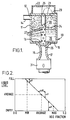
- Figure 2 graphically illustrates the relationship between the liquid level in the apparatus of Figure 1 and the void fraction drawn off.
- The apparatus of Figure 1 comprises a vessel or
container 10 of generally upright cylindrical form of which the interior is closed, except for the fluid inlets and the outlets to be described. At the upper region of thecylindrical side wall 11 of the container, there is provided aninlet port 12 communicating by apipe 14 with a source (not shown) of a multiphase fluid. Aliquid outlet port 15 is provided centrally .in thefloor 16 of thecontainer 10 and communicates with an outlet or discharge pipe or fitting 17 having aninternal constriction 19 which forms a venturi. Agas outlet port 20 in theroof 21 of the container communicates with anupper chamber 22 mounted on the roof. Also communicating with thechamber 22 is a generally vertical pipe 24 extending downwardly from acentral aperture 25 in the roof. The pipe 24 extends downwardly through the container interior into the discharge fitting 17, the loweropen end 26 of the pipe being located concentrically within the fitting just above theconstriction 19 forming the venturi. - The upper portion of the
container 10 thus communicates with the pipe 24 by way of thechamber 22 and for a reason explained below, this upper container portion also communicates with the pipe 24 through a series ofperforations 27 through the pipe wall. Theperforations 27 extend along substantially the entire length of the pipe 24 within the container. - The liquid component of a multi-phase fluid flow entering the container by way of the
inlet port 12 tends to separate under gravity from the gaseous component and forms apool 29 in the lower part of the container. A body of the gaseous component occupies the upper part of the container, above the free surface of the liquid pool. - The liquid component is withdrawn from the
pool 29 in the container through thedischarge port 15 under gravity, with or without the assistance of adownstream pump 31 connected for example at the lower end of thedischarge pipe 17, as schematically shown, and the effect of the venturi is to draw the gas from the upper part of the tank interior through the pipe 24 in admixture with the liquid phase, so that a homogenized or substantially homogenized fluid is obtained in thedischarge pipe 17. If the multi-phase fluid flow entering the container interior is already homogenous or approximately so, then the mixture will be discharged through thepipe 17 by way of both theoutlet port 15 and theopen end 26. - The void fraction α of the fluid discharged from the
container 10 depends on the dimensions of the venturi, and can be made independent of the total flow rate QT, the liquid level h in the container, and the absolute pressure. - Assuming that both some liquid and some gas are present in the container, the total pressure drop for the gas and for the liquid phases flowing through it will be equal, and the void fraction from the container can be obtained from the resulting equation as follows:

- AT -
- the cross-sectional area of the container,
- AL -
- the cross-sectional area of the liquid in the venturi,
- AG -
- the cross-sectional area of the gas in the venturi,
- ξL -
- the total liquid loss coefficient,
- ξG -
- the total gas loss coefficient,
- ρL -
- the liquid density,
- ρG -
- the gas density, and
- g -
- gravity.
- During steady flow conditions, the average void fraction drawn from the container will equal the average void fraction entering it. To ensure that both liquid and gas are always present in the container, it is convenient to decrease the gas fraction drawn off as the liquid level increases, and vice versa, and this is achieved by the
perforations 27 in the pipe 24. The perforated pipe 24 thus acts as an integral regulator allowing a variation in the void fraction. - The relation between the liquid level in the container and the void fraction drawn from it (the mixing unit characteristic) is illustrated in Figure 2. Any desired mixing unit characteristic can be obtained by appropriate choice of dimensions of the venturi and the
perforations 27 in the pipe portion 24. - It will be readily appreciated that the invention can be embodied in a variety of ways other than as specifically described and illustrated, within the scope of the claims.
Claims (11)
- A method of homogenizing a liquid phase and a gas phase of a flowing non-uniform multiphase fluid, the method comprising the steps of:a) separating the two phases of the flowing fluid into adjacent gas and liquid bodies within a closed vessel (11) by gravity with the gas phase above the liquid phase;b) causing the two phases to flow through a venturi constriction (19) in a duct (17) for mixing and homogenizing the phases of the flowing fluid and to flow away from the vessel by way of an opening (15) in a wall of the vessel, which opening forms an inlet end for the duct (17), and by way of a piping (24) having an inlet end within the vessel interior spaced from the opening (15) and immersed in one phase of the fluid and an outlet end within the duct at or upstream of the venturi constriction (19), whereby the flow of liquid through the venturi constriction creates suction by which the gas is drawn into the liquid flow.
- A method as claimed in claim 1, wherein the two phases of the fluid flow through the venturi constriction at rates tending to maintain both phases of the flow present within the vessel (11).
- A method as claimed in claim 2, wherein the two phases of the fluid flow from the vessel in relative amounts dependent on the level of the liquid phase.
- A method as claimed in claim 1, 2, or 3, wherein the flow of the liquid phase and the gas phase through the venturi constriction is effected by the action of gravity.
- A method as claimed in claim 4, wherein the flow of the liquid phase and the gas phase through the venturi constriction is assisted by a suction pump (34) communicating with the duct (17) downstream of the venturi constriction.
- An apparatus for carrying out the process of claim 1 comprising a closed vessel (11) for receiving the non-uniform multiphase flow and for containing the gas and liquid bodies which have been separated under gravity, a duct (17) having a venturi constriction (19) therein for mixing and homogenizing the two phases and a piping (24) having an inlet end (25) and an outlet end (26), the piping outlet end (26) being within the duct at or upstream of the venturi constriction, wherein the vessel (11) has a common inlet (12,14) for the two phases, the duct (17) having an inlet communicating with the interior of the vessel at an opening (15) in a wall of the vessel, and the inlet end of the piping (24) communicates with the vessel interior at a position spaced from the opening (15).
- An apparatus as claimed in claim 6, wherein the piping (24) extends from the outlet end thereof through the opening (15) and into the vessel (11).
- An apparatus as claimed in claim 7, wherein the piping (24) extends through the vessel (11) and communicates with the vessel interior by way of a chamber (22) located adjacent the vessel (11) and with which the piping communicates, the chamber being in communication with the vessel.
- An apparatus as claimed in claim 7 or 8 wherein the piping (24) has a plurality of apertures (27) spaced apart along its length within the vessel (11).
- An apparatus as claimed in claim 6, 7, 8, or 9, wherein the opening (15) is located in the lower region of the vessel (11).
- An apparatus as claimed in any one of claims 6 to 10 wherein the outlet end of the discharge duct (17) communicates with the inlet of a suction pump (31).
Applications Claiming Priority (2)
| Application Number | Priority Date | Filing Date | Title |
|---|---|---|---|
| GB8900841 | 1989-01-16 | ||
| GB898900841A GB8900841D0 (en) | 1989-01-16 | 1989-01-16 | Homogenization of a multi-phase fluid |
Publications (3)
| Publication Number | Publication Date |
|---|---|
| EP0379319A2 EP0379319A2 (en) | 1990-07-25 |
| EP0379319A3 EP0379319A3 (en) | 1992-05-13 |
| EP0379319B1 true EP0379319B1 (en) | 1996-09-25 |
Family
ID=10650066
Family Applications (1)
| Application Number | Title | Priority Date | Filing Date |
|---|---|---|---|
| EP90300391A Expired - Lifetime EP0379319B1 (en) | 1989-01-16 | 1990-01-15 | Fluid homogenization |
Country Status (11)
| Country | Link |
|---|---|
| US (1) | US5035842A (en) |
| EP (1) | EP0379319B1 (en) |
| AT (1) | ATE143287T1 (en) |
| AU (1) | AU627539B2 (en) |
| BR (1) | BR9000140A (en) |
| CA (1) | CA2007855C (en) |
| DE (1) | DE69028641T2 (en) |
| DK (1) | DK0379319T3 (en) |
| ES (1) | ES2091788T3 (en) |
| GB (1) | GB8900841D0 (en) |
| NO (1) | NO176310C (en) |
Families Citing this family (22)
| Publication number | Priority date | Publication date | Assignee | Title |
|---|---|---|---|---|
| US5254292A (en) * | 1989-02-02 | 1993-10-19 | Institut Francais Du Petrole | Device for regulating and reducing the fluctuations in a polyphasic flow, and its use |
| GB8910372D0 (en) * | 1989-05-05 | 1989-06-21 | Framo Dev Ltd | Multiphase process mixing and measuring system |
| DE4126397C2 (en) * | 1991-08-09 | 1994-06-23 | Europ Chemical Ind | Method and device for foam generation |
| DK0549440T3 (en) * | 1991-12-27 | 1997-03-24 | Inst Francais Du Petrole | Process for optimizing a device for controlling and attenuating a multi-phase flow and device obtained by the method |
| FR2688147B1 (en) * | 1992-03-09 | 1994-09-23 | Technicatome | DEVICE FOR RESORBING GAS CAPS IN A TWO - PHASE FLOW. |
| BR9303910A (en) * | 1993-09-27 | 1995-05-30 | Petroleo Brasileiro Sa | Method for eliminating severe intermittency in underwater multiphase flow lines |
| US6017022A (en) * | 1995-10-12 | 2000-01-25 | The Dow Chemical Company | Shear mixing apparatus and use thereof |
| US5885466A (en) * | 1997-01-02 | 1999-03-23 | Kelly; Bill B. | Water aerator and method |
| CA2303780C (en) | 1997-09-15 | 2008-07-29 | Den Norske Stats Oljeselskap A.S. | Fluid separation system |
| AU9086598A (en) | 1997-09-15 | 1999-04-05 | Den Norske Stats Oljeselskap A.S. | Separation of acid gas from natural gas |
| AU9087698A (en) | 1997-09-15 | 1999-04-05 | Den Norske Stats Oljeselskap A.S. | Separation of acid gases from gas mixtures |
| CA2303779C (en) | 1997-09-15 | 2008-07-22 | Den Norske Stats Oljeselskap A.S. | Fluid separation system |
| GB9906717D0 (en) * | 1999-03-23 | 1999-05-19 | Norske Stats Oljeselskap | Method and apparatus for drying of natural gas |
| FR2861605B1 (en) * | 2003-11-05 | 2005-12-30 | Inst Francais Du Petrole | METHOD FOR MIXING AND DISPENSING A LIQUID PHASE AND A GAS PHASE |
| GB0413714D0 (en) * | 2004-06-18 | 2004-07-21 | Ctour Process Systems | Method |
| US7377492B2 (en) * | 2004-08-11 | 2008-05-27 | A Better Power, Llc | Hydraulic liquid pumping system |
| DE102006045088A1 (en) * | 2006-09-21 | 2008-03-27 | Basf Ag | Mixing a liquid or suspension beneath a gas space in a closed container comprises supplying a stream of the liquid or suspension as a drive jet for a submerged ejector which aspirates gas from the gas space |
| DE102010019238A1 (en) * | 2010-05-03 | 2011-11-24 | Joh. Heinr. Bornemann Gmbh | Container, sump and multi-phase pump system and method for separating and splitting a multi-phase mixture |
| GB2483438A (en) * | 2010-09-06 | 2012-03-14 | Framo Eng As | Homogenising a multiphase fluid |
| NO337168B1 (en) | 2012-07-05 | 2016-02-01 | Fmc Kongsberg Subsea As | Apparatus and method for mixing at least a first and second fluid phases |
| US9463424B2 (en) | 2014-07-09 | 2016-10-11 | Onesubsea Ip Uk Limited | Actuatable flow conditioning apparatus |
| US10844698B2 (en) | 2017-12-01 | 2020-11-24 | Onesubsea Ip Uk Limited | Liquid retainer for a production system |
Citations (1)
| Publication number | Priority date | Publication date | Assignee | Title |
|---|---|---|---|---|
| US4267052A (en) * | 1979-12-10 | 1981-05-12 | Chang Shih Chih | Aeration method and apparatus |
Family Cites Families (14)
| Publication number | Priority date | Publication date | Assignee | Title |
|---|---|---|---|---|
| US543410A (en) * | 1895-07-23 | taylor | ||
| AT96928B (en) * | 1922-12-02 | 1924-05-10 | Ottokar Ing Schwarz | Device to prevent water power machines from wading in the event of a backwater |
| US3371618A (en) * | 1966-02-18 | 1968-03-05 | Chambers John | Pump |
| US4017565A (en) * | 1973-07-13 | 1977-04-12 | Mueller Hans | Device for admixing a gaseous and a liquid phase |
| US4051204A (en) * | 1973-12-21 | 1977-09-27 | Hans Muller | Apparatus for mixing a liquid phase and a gaseous phase |
| US3960175A (en) * | 1974-08-16 | 1976-06-01 | Veb Chemieanlagenbau Und Montagekombinat Leipzig | Installation for charging liquids, particularly fermentation liquids, with gas |
| FR2355554A1 (en) * | 1976-02-27 | 1978-01-20 | Cem Comp Electro Mec | Gaseous bubble injection device in liq. - for flotation of suspended and colloidal matter |
| JPS5419279Y2 (en) * | 1976-04-09 | 1979-07-17 | ||
| US4168705A (en) * | 1977-05-31 | 1979-09-25 | Jacuzzi Bros., Inc. | Float and check valve for hydrotherapy unit air intake |
| EP0009520B1 (en) * | 1978-08-09 | 1983-07-20 | R.E. Folland Consultants Inc. | Emulsifying system and method for mixing accurate quantities of two or more liquids |
| AU533414B2 (en) * | 1979-06-01 | 1983-11-24 | Mishinski, J. | Vacuum operated mixing device for liquids |
| GB2106408A (en) * | 1981-08-15 | 1983-04-13 | British Petroleum Co Plc | Multi-orifice mixing device |
| US4389312A (en) * | 1981-10-05 | 1983-06-21 | Harold Beard | Variable venturi sewerage aerator |
| JPH01257414A (en) * | 1987-12-14 | 1989-10-13 | Masuda Hideo | Diffuser for mixed gas |
-
1989
- 1989-01-16 GB GB898900841A patent/GB8900841D0/en active Pending
-
1990
- 1990-01-12 NO NO900158A patent/NO176310C/en not_active IP Right Cessation
- 1990-01-15 DK DK90300391.1T patent/DK0379319T3/da active
- 1990-01-15 BR BR909000140A patent/BR9000140A/en not_active IP Right Cessation
- 1990-01-15 DE DE69028641T patent/DE69028641T2/en not_active Expired - Fee Related
- 1990-01-15 ES ES90300391T patent/ES2091788T3/en not_active Expired - Lifetime
- 1990-01-15 EP EP90300391A patent/EP0379319B1/en not_active Expired - Lifetime
- 1990-01-15 AT AT90300391T patent/ATE143287T1/en active
- 1990-01-16 US US07/465,955 patent/US5035842A/en not_active Expired - Lifetime
- 1990-01-16 AU AU47998/90A patent/AU627539B2/en not_active Expired
- 1990-01-16 CA CA002007855A patent/CA2007855C/en not_active Expired - Lifetime
Patent Citations (1)
| Publication number | Priority date | Publication date | Assignee | Title |
|---|---|---|---|---|
| US4267052A (en) * | 1979-12-10 | 1981-05-12 | Chang Shih Chih | Aeration method and apparatus |
Also Published As
| Publication number | Publication date |
|---|---|
| NO900158D0 (en) | 1990-01-12 |
| AU627539B2 (en) | 1992-08-27 |
| ATE143287T1 (en) | 1996-10-15 |
| DK0379319T3 (en) | 1997-03-03 |
| DE69028641D1 (en) | 1996-10-31 |
| CA2007855C (en) | 1994-04-26 |
| NO176310B (en) | 1994-12-05 |
| NO900158L (en) | 1990-07-17 |
| NO176310C (en) | 1995-03-15 |
| AU4799890A (en) | 1990-07-19 |
| US5035842A (en) | 1991-07-30 |
| CA2007855A1 (en) | 1990-07-16 |
| ES2091788T3 (en) | 1996-11-16 |
| GB8900841D0 (en) | 1989-03-08 |
| EP0379319A2 (en) | 1990-07-25 |
| EP0379319A3 (en) | 1992-05-13 |
| DE69028641T2 (en) | 1997-02-13 |
| BR9000140A (en) | 1990-10-23 |
Similar Documents
| Publication | Publication Date | Title |
|---|---|---|
| EP0379319B1 (en) | Fluid homogenization | |
| RU2093257C1 (en) | Device for mixing or homogenization of liquid and fluid medium and method of mixing or homogenization of liquid and fluid medium | |
| US8088286B2 (en) | Gravity separator, and a method for separating a mixture containing water, oil, and gas | |
| US8298418B2 (en) | Method and installation for bringing ozone into contact with a flow of liquid, in particular a flow of drinking water or wastewater | |
| EP0027912A1 (en) | Apparatus for contacting liquid with a gas | |
| US6458191B1 (en) | Separator inlet | |
| JP2001513018A (en) | Tank stirrer with air bubbler | |
| US6079864A (en) | Horizontal flow generation system | |
| EP0845290A1 (en) | Aeration and mixing unit | |
| JP3204978B2 (en) | Reactor | |
| JPH1066962A (en) | Sewage treating device | |
| EP1225970B1 (en) | Equipment for the leaching of solid matter from sludge | |
| EP0002369A1 (en) | Aerator and method of aerating liquid | |
| US3844723A (en) | Multi-stage counter-current liquid-liquid contact apparatus | |
| AU660813B2 (en) | Aerator device | |
| US5447370A (en) | Device for regulating fluctuations of the composition of a multiphase flow | |
| JP7176744B2 (en) | liquid fertilizer mixer | |
| US8777476B2 (en) | Flow conditioning apparatus | |
| CN217458897U (en) | Novel advection air supporting experiment device | |
| JPH07308569A (en) | Bubble tower | |
| JPH0234649B2 (en) | ||
| CN110498467A (en) | Air-floating apparatus for Industrial Wastewater Treatment | |
| JPH0749294A (en) | Gas-liquid separating-converting device | |
| JPH0347502A (en) | Liquid separation apparatus and liquid separation process |
Legal Events
| Date | Code | Title | Description |
|---|---|---|---|
| PUAI | Public reference made under article 153(3) epc to a published international application that has entered the european phase |
Free format text: ORIGINAL CODE: 0009012 |
|
| AK | Designated contracting states |
Kind code of ref document: A2 Designated state(s): AT BE CH DE DK ES FR GB GR IT LI LU NL SE |
|
| PUAL | Search report despatched |
Free format text: ORIGINAL CODE: 0009013 |
|
| AK | Designated contracting states |
Kind code of ref document: A3 Designated state(s): AT BE CH DE DK ES FR GB GR IT LI LU NL SE |
|
| 17P | Request for examination filed |
Effective date: 19920826 |
|
| 17Q | First examination report despatched |
Effective date: 19930105 |
|
| GRAG | Despatch of communication of intention to grant |
Free format text: ORIGINAL CODE: EPIDOS AGRA |
|
| GRAH | Despatch of communication of intention to grant a patent |
Free format text: ORIGINAL CODE: EPIDOS IGRA |
|
| GRAH | Despatch of communication of intention to grant a patent |
Free format text: ORIGINAL CODE: EPIDOS IGRA |
|
| GRAA | (expected) grant |
Free format text: ORIGINAL CODE: 0009210 |
|
| ITF | It: translation for a ep patent filed |
Owner name: BARZANO' E ZANARDO ROMA S.P.A. |
|
| AK | Designated contracting states |
Kind code of ref document: B1 Designated state(s): AT BE CH DE DK ES FR GB GR IT LI LU NL SE |
|
| PG25 | Lapsed in a contracting state [announced via postgrant information from national office to epo] |
Ref country code: GR Free format text: LAPSE BECAUSE OF FAILURE TO SUBMIT A TRANSLATION OF THE DESCRIPTION OR TO PAY THE FEE WITHIN THE PRESCRIBED TIME-LIMIT Effective date: 19960925 Ref country code: AT Effective date: 19960925 Ref country code: BE Effective date: 19960925 Ref country code: CH Effective date: 19960925 Ref country code: LI Effective date: 19960925 |
|
| REF | Corresponds to: |
Ref document number: 143287 Country of ref document: AT Date of ref document: 19961015 Kind code of ref document: T |
|
| REF | Corresponds to: |
Ref document number: 69028641 Country of ref document: DE Date of ref document: 19961031 |
|
| ET | Fr: translation filed | ||
| REG | Reference to a national code |
Ref country code: ES Ref legal event code: FG2A Ref document number: 2091788 Country of ref document: ES Kind code of ref document: T3 |
|
| PG25 | Lapsed in a contracting state [announced via postgrant information from national office to epo] |
Ref country code: SE Effective date: 19961225 |
|
| PG25 | Lapsed in a contracting state [announced via postgrant information from national office to epo] |
Ref country code: LU Free format text: LAPSE BECAUSE OF NON-PAYMENT OF DUE FEES Effective date: 19970131 |
|
| REG | Reference to a national code |
Ref country code: DK Ref legal event code: T3 |
|
| REG | Reference to a national code |
Ref country code: CH Ref legal event code: PL |
|
| REG | Reference to a national code |
Ref country code: GB Ref legal event code: 732E |
|
| PLBE | No opposition filed within time limit |
Free format text: ORIGINAL CODE: 0009261 |
|
| STAA | Information on the status of an ep patent application or granted ep patent |
Free format text: STATUS: NO OPPOSITION FILED WITHIN TIME LIMIT |
|
| REG | Reference to a national code |
Ref country code: FR Ref legal event code: TP |
|
| NLS | Nl: assignments of ep-patents |
Owner name: FRAMO ENGINEERING A/S |
|
| REG | Reference to a national code |
Ref country code: ES Ref legal event code: PC2A |
|
| 26N | No opposition filed | ||
| REG | Reference to a national code |
Ref country code: FR Ref legal event code: CA |
|
| PGFP | Annual fee paid to national office [announced via postgrant information from national office to epo] |
Ref country code: DE Payment date: 19991231 Year of fee payment: 11 |
|
| PGFP | Annual fee paid to national office [announced via postgrant information from national office to epo] |
Ref country code: NL Payment date: 20000131 Year of fee payment: 11 Ref country code: ES Payment date: 20000131 Year of fee payment: 11 |
|
| PG25 | Lapsed in a contracting state [announced via postgrant information from national office to epo] |
Ref country code: ES Free format text: LAPSE BECAUSE OF NON-PAYMENT OF DUE FEES Effective date: 20010116 |
|
| PG25 | Lapsed in a contracting state [announced via postgrant information from national office to epo] |
Ref country code: NL Free format text: LAPSE BECAUSE OF NON-PAYMENT OF DUE FEES Effective date: 20010801 |
|
| NLV4 | Nl: lapsed or anulled due to non-payment of the annual fee |
Effective date: 20010801 |
|
| PG25 | Lapsed in a contracting state [announced via postgrant information from national office to epo] |
Ref country code: DE Free format text: LAPSE BECAUSE OF NON-PAYMENT OF DUE FEES Effective date: 20011101 |
|
| REG | Reference to a national code |
Ref country code: GB Ref legal event code: IF02 |
|
| REG | Reference to a national code |
Ref country code: ES Ref legal event code: FD2A Effective date: 20021016 |
|
| PGFP | Annual fee paid to national office [announced via postgrant information from national office to epo] |
Ref country code: DK Payment date: 20090302 Year of fee payment: 20 |
|
| PGFP | Annual fee paid to national office [announced via postgrant information from national office to epo] |
Ref country code: GB Payment date: 20090211 Year of fee payment: 20 |
|
| PGFP | Annual fee paid to national office [announced via postgrant information from national office to epo] |
Ref country code: IT Payment date: 20090226 Year of fee payment: 20 |
|
| PGFP | Annual fee paid to national office [announced via postgrant information from national office to epo] |
Ref country code: FR Payment date: 20090225 Year of fee payment: 20 |
|
| REG | Reference to a national code |
Ref country code: DK Ref legal event code: EUP |
|
| REG | Reference to a national code |
Ref country code: GB Ref legal event code: PE20 Expiry date: 20100114 |
|
| PG25 | Lapsed in a contracting state [announced via postgrant information from national office to epo] |
Ref country code: GB Free format text: LAPSE BECAUSE OF EXPIRATION OF PROTECTION Effective date: 20100114 |