EP0379095A1 - Synchronous transport-module STM-O - Google Patents
Synchronous transport-module STM-O Download PDFInfo
- Publication number
- EP0379095A1 EP0379095A1 EP19900100646 EP90100646A EP0379095A1 EP 0379095 A1 EP0379095 A1 EP 0379095A1 EP 19900100646 EP19900100646 EP 19900100646 EP 90100646 A EP90100646 A EP 90100646A EP 0379095 A1 EP0379095 A1 EP 0379095A1
- Authority
- EP
- European Patent Office
- Prior art keywords
- column
- stm
- transport module
- rows
- columns
- Prior art date
- Legal status (The legal status is an assumption and is not a legal conclusion. Google has not performed a legal analysis and makes no representation as to the accuracy of the status listed.)
- Withdrawn
Links
Images

Classifications
-
- H—ELECTRICITY
- H04—ELECTRIC COMMUNICATION TECHNIQUE
- H04J—MULTIPLEX COMMUNICATION
- H04J3/00—Time-division multiplex systems
- H04J3/16—Time-division multiplex systems in which the time allocation to individual channels within a transmission cycle is variable, e.g. to accommodate varying complexity of signals, to vary number of channels transmitted
- H04J3/1605—Fixed allocated frame structures
- H04J3/1611—Synchronous digital hierarchy [SDH] or SONET
Definitions
- the invention relates to a synchronous transport module STM-0 with nine rows, with a header consisting of a first column group, which contains a section header in the first three and five last rows and a data pointer section in the fourth row, and with a user information block consisting of a second column group (administrative unit) for recording one byte (octet) per column and line to supplement the synchronous digital multiplex hierarchy (SDH) in accordance with the CCITT recommendations G.707, G.708 and G .709.
- SDH synchronous digital multiplex hierarchy
- the synchronous digital multiplex hierarchy comprises transport modules STM-1 for 155.52 Mbit / s, transport modules STM-4 for 622.08 Mbit / s and transport modules STM-16 for 2488.32 Mbit / s s.
- the European hierarchy for plesiochronous digital signals works with bit rates of 2.048 Mbit / s, 8.448 Mbit / s, 34.368 Mbit / s and 139.264 Mbit / s and the North American hierarchy for plesiochronous digital signals uses bit rates of 1.544 Mbit / s, 6.312 Mbit / s and 44.736 Mbit / s.
- the synchronous transport module STM-1 has the frame structure described at the beginning.
- the frame contains 2430 bytes and is shown with 270 columns and 9 rows.
- H4 signals with a bit rate of 139.264 Mbit / s are preferably to be transmitted in the useful information block AU-4.
- a synchronous transport signal STS-1 is also provided as a basic block for a synchronous optical network SONET, which has a section overhead of 9 bytes and a line overhead of 1 byte , A user information block (Administrative Unit) AU-32 and a data pointer (pointer) AU-32 PTR in the same structure as that of the transport modules STM-1.
- the synchronous transport signal STS 1 has a transmission capacity of 51.84 Mbit / s, which is exactly one third of the transmission capacity of the synchronous transport module STM-1. This can record an H22 signal with a bit rate of 44.736 Mbit / s.
- a byte-by-byte interleaving of three synchronous transport signals STS-1 results in a synchronous transport signal STS-3, the section header of which corresponds to that of the synchronous transport module STM-1.
- STS-3 the section header of which corresponds to that of the synchronous transport module STM-1.
- the synchronous transport signal STS-1 which can receive an H22 signal with a bit rate of 44.736 Mbit / s, is also covered as a transmission system according to CCITT.
- the object of the invention is to provide a synchronous transport module which can receive an H21 signal with a bit rate of 34.368 Mbit / s in a corresponding manner.
- a first embodiment of the synchronous transport module STM-0 according to the invention contains the features of claim 2 and a second embodiment has the features of claim 3. The latter can additionally receive the feature of claim 4.
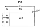
- FIG. 1 shows the synchronous transport module STM-0 according to the invention. This consists of sixty-eight columns Sp and nine rows Z. The first three and the last five rows Z of the first three columns Sp form the section header SOH. The fourth line is the data pointer section PTRS. The subsequent sixty-five columns Sp form the useful information block AU-31 over all nine rows Z.
- Figure 2 also shows a synchronous transport module STM-0.
- NPI zero pointer indication
- a virtual container VC-31 according to CCITT is shown, which contains a path header VC-31 POH and then a container C-31 with sixty-five columns Sp and nine rows Z in a first column over six rows.
- the letter-number combinations in the path header VC-31 POH indicate standardized uses.
- the data pointer AU-31 PTR belonging to the virtual container VC-31 is accommodated in the first three rows Z of the first column Sp of the useful information block AU-31 and is designated H1, H2 and H3.
- Bytes H1 and H2 indicate the location of the beginning of the virtual container VC-31.
- Byte H3 receives information bits when negative stuffing occurs.
- FIG. 3 again shows the synchronous transport module STM-0, in whose data pointer section PTRS according to FIG. 1 the data pointer AU-31 * PTR is now inserted.
- a virtual container VC-31 * differs from the virtual container VC-31 according to FIG. 2 in that the path header VC-31 * POH comprises 9 bytes.
- the additional bytes Z3, Z4 and Z5 can accommodate a network node head NOH (Network Node Overhead). This variant does not have the disadvantages according to points 1 and 2.
- Both virtual containers VC-31 and VC-31 * can receive an H21 signal with a bit rate of 34.368 Mbit / s.
- Figure 4 shows a synchronous transport module STM-1 according to CCITT with 270 columns Sp and 9 rows Z. It contains a section header SOH 'in the first three and five last rows Z of the first nine columns Sp.
- the useful information block AU-4 comprises 261st Columns Sp and 9 lines Z.
- Four virtual containers VC-31 * according to FIG. 3 are to be inserted into it in bytes. The last 260 columns Sp are used for this. The first column Sp of the useful information block AU-4 therefore remains free.
- the four data pointers AU-31 * PTR for the four virtual containers VC-31 * are accommodated in the fourth row Z of the first ten columns Sp and in the second and third row Z of the tenth column. The rest of the tenth column can be used for a network node head NOH.
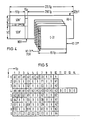
- FIG. 5 shows the first fourteen columns of the synchronous transport module STM-1.
- the partially standardized use of the bytes of the section header SOH ' is of no interest to the invention.
- the four data pointers AU-31 * PTR are each accommodated with bytes H1 and H2.
- the fourth row of the seventh to tenth column Sp with four bytes H3 offer a negative stuffing possibility
- the fourth row Z of the eleventh to fourteenth column Sp with bytes 0 enables positive stuffing.
Abstract
Description
Die Erfindung bezieht sich auf ein synchrones Transport-Modul STM-0 mit neun Zeilen, mit einem aus einer ersten Spaltengruppe bestehenden Kopfteil, der in den drei ersten und fünf letzten Zeilen einen Abschnittskopf (Section Overhead) und in der vierten Zeile einen Datenzeigerabschnitt enthält, und mit einem aus einer zweiten Spaltengruppe (Administrative Unit) bestehenden Nutzinformationsblock zur Aufnahme je eines Bytes (Oktetts) pro Spalte und Zeile zur Ergänzung der Synchron-Digital-Multiplexhierarchie (SDH) gemäß den CCITT-Empfehlungen G.707, G.708 und G.709.The invention relates to a synchronous transport module STM-0 with nine rows, with a header consisting of a first column group, which contains a section header in the first three and five last rows and a data pointer section in the fourth row, and with a user information block consisting of a second column group (administrative unit) for recording one byte (octet) per column and line to supplement the synchronous digital multiplex hierarchy (SDH) in accordance with the CCITT recommendations G.707, G.708 and G .709.
Die wichtigsten Digitalsignalhierarchien sind in der Zeitschrift "telcom report", 11 (1988), Heft 5, Seiten 160 bis 163 in der ersten Figur beschrieben. Die Synchron-Digital-Multiplexhierarchie (SDH) umfaßt Transport-Moduln STM-1 für 155,52 Mbit/s, Transport-Moduln STM-4 für 622,08 Mbit/s und Transport-Moduln STM-16 für 2488,32 Mbit/s. Die europäische Hierarchie für plesiochrone Digitalsignale arbeitet mit Bitraten von 2,048 Mbit/s, 8,448 Mbit/s, 34,368 Mbit/s und 139,264 Mbit/s und die nordamerikanische Hierarchie für plesiochrone Digitalsignale verwendet Bitraten von 1,544 Mbit/s, 6,312 Mbit/s und 44,736 Mbit/s.The most important digital signal hierarchies are described in the first figure in the journal "telcom report", 11 (1988),
Die Zeitschrift "ntz", 41 (1988) Heft 10, Seiten 570 -574 zeigt in Bild 3 ein synchrones Transport-Modul STM-1, in Bild 7 einen Abschnittskopf (Section Overhead) und AU-Datenzeiger (Administrativ Unit Pointers) und in Bild 8 Pfadköpfe (Path Overheads) für verschiedene virtuelle Container. Der Pfadkopf VC-31 POH umfaßt sechs Bytes. Weitere drei Bytes wie bei den Pfadköpfen VC-32 POH und VC-4 POH sind nicht vorhanden.The magazine "ntz", 41 (1988)
Das synchrone Transport-Modul STM-1 weist die eingangs beschriebene Rahmenstruktur auf. Der Rahmen enthält 2430 byte und ist mit 270 Spalten und 9 Zeilen dargestellt. Im Nutzinformationsblock AU-4 sollen vorzugsweise H4-Signale einer Bitrate von 139,264 Mbit/s übertragen werden.The synchronous transport module STM-1 has the frame structure described at the beginning. The frame contains 2430 bytes and is shown with 270 columns and 9 rows. H4 signals with a bit rate of 139.264 Mbit / s are preferably to be transmitted in the useful information block AU-4.
Nach der US-Norm (ANSI) ist für ein Synchrones Optisches Netzwerk SONET weiter als Basis-Block ein synchrones Transport-Signal STS-1 vorgesehen, das einen Abschnittskopf (Section Overhead) von 9 Byte, einen Leitungskopf (Line Overhead) von 1 Byte, einen Nutzinformationsblock (Administrative Unit) AU-32 und einen Datenzeiger (pointer) AU-32 PTR in derselben Struktur wie der der Transport-Moduln STM-1 aufweist. Das synchrone Transport-Signal STS 1 besitzt eine Übertragungskapazität von 51,84 Mbit/s, was exakt ein Drittel der Übertragungskapazität des synchronen Transport-Moduls STM-1 ist. Dieses vermag ein H22-Signal einer Bitrate von 44,736 Mbit/s aufzunehmen.According to the US standard (ANSI), a synchronous transport signal STS-1 is also provided as a basic block for a synchronous optical network SONET, which has a section overhead of 9 bytes and a line overhead of 1 byte , A user information block (Administrative Unit) AU-32 and a data pointer (pointer) AU-32 PTR in the same structure as that of the transport modules STM-1. The synchronous transport signal STS 1 has a transmission capacity of 51.84 Mbit / s, which is exactly one third of the transmission capacity of the synchronous transport module STM-1. This can record an H22 signal with a bit rate of 44.736 Mbit / s.
Eine byteweise Verschachtelung von drei synchronen Transport-Signalen STS-1 ergibt ein synchrones Transport-Signal STS-3, dessen Abschnittskopf dem des synchronen Transport-Moduls STM-1 entspricht. Damit ist das synchrone Transport-Signal STS-1, das ein H22-Signal einer Bitrate von 44,736 Mbit/s aufnehmen kann, als Übertragungssystem auch nach CCITT abgedeckt.A byte-by-byte interleaving of three synchronous transport signals STS-1 results in a synchronous transport signal STS-3, the section header of which corresponds to that of the synchronous transport module STM-1. This means that the synchronous transport signal STS-1, which can receive an H22 signal with a bit rate of 44.736 Mbit / s, is also covered as a transmission system according to CCITT.
Aufgabe der Erfindung ist es, ein synchrones Transport-Modul anzugeben, das in entsprechender Weise ein H21-Signal einer Bitrate von 34,368 Mbit/s aufzunehmen vermag.The object of the invention is to provide a synchronous transport module which can receive an H21 signal with a bit rate of 34.368 Mbit / s in a corresponding manner.
Ausgehend von dem synchronen Transport-Modul der einleitend geschilderten ARt wird diese Aufgabe erfindungsgemäß mit den Merkmalen des Anspruchs 1 gelöst.Starting from the synchronous transport module of the ARt described in the introduction, this object is achieved according to the invention with the features of
Eine erste Ausgestaltung des erfindungsgemäßen synchronen Transport-Moduls STM-0 enthält die Merkmale des Anspruchs 2 und eine zweite Ausgestaltung die Merkmale des Anspruchs 3. Letztere kann zusätzlich das Merkmal des Anspruchs 4 erhalten.A first embodiment of the synchronous transport module STM-0 according to the invention contains the features of
Eine Anwendung des erfindungsgemäßen synchronen Transport-Moduls STM-0 ist den Merkmalen des Anspruchs 5 zu entnehmen.An application of the synchronous transport module STM-0 according to the invention can be gathered from the features of
Anhand von Ausführungsbeispielen wird die Erfindung nachstehend näher erläutert.
Figur 1 zeigt das erfindungsgemäße synchrone Transport-Modul STM-0.Figur 2 zeigt dieses synchrone Transport-Modul STM-0 mit einem virtuellen Container VC-31,Figur 3 zeigt dieses synchrone Transport-Modul STM-0 mit einem Virtuellen Containern VC-31*,Figur 4 zeigt ein synchrones Transport-Modul STM-1 mit vier virtuellen Container VC-31* undFigur 5 zeigt die ersten Spalten des synchronen Transport-Moduls STM-1.
- FIG. 1 shows the synchronous transport module STM-0 according to the invention.
- FIG. 2 shows this synchronous transport module STM-0 with a virtual container VC-31,
- FIG. 3 shows this synchronous transport module STM-0 with a virtual container VC-31 *,
- Figure 4 shows a synchronous transport module STM-1 with four virtual containers VC-31 * and
- FIG. 5 shows the first columns of the synchronous transport module STM-1.
Figur 1 zeigt das erfindungsgemäße synchrone Transport-Modul STM-0. Dieses besteht aus achtundsechzig Spalten Sp und neun Zeilen Z. Die ersten drei und die letzten fünf Zeilen Z der ersten drei Spalten Sp bilden den Abschnittskopf SOH. Die vierte Zeile ist der Datenzeigerabschnitt PTRS. Die anschließenden fünfundsechzig Spalten Sp bilden über alle neun Zeilen Z den Nutzinformationsblock AU-31.FIG. 1 shows the synchronous transport module STM-0 according to the invention. This consists of sixty-eight columns Sp and nine rows Z. The first three and the last five rows Z of the first three columns Sp form the section header SOH. The fourth line is the data pointer section PTRS. The subsequent sixty-five columns Sp form the useful information block AU-31 over all nine rows Z.
Figur 2 zeigt ebenfalls ein synchrones Transport-Modul STM-0. Im Datenzeigerabschnitt PTRS ist hier eine Anzeige NPI (Null Pointer Indication) für fehlenden Datenzeiger untergebracht.Figure 2 also shows a synchronous transport module STM-0. In the data pointer section PTRS there is an NPI (zero pointer indication) display for missing data pointers.
Weiter ist ein virtueller Container VC-31 nach CCITT gezeigt, der in einer ersten Spalte über sechs Zeilen einen Pfadkopfteil VC-31 POH und anschließend einen Container C-31 mit fünfundsechzig Spalten Sp und neun Zeilen Z enthält. Die Buchstaben-Ziffer-Kombinationen im Pfadkopfteil VC-31 POH bezeichnen genormte Verwendungen.Furthermore, a virtual container VC-31 according to CCITT is shown, which contains a path header VC-31 POH and then a container C-31 with sixty-five columns Sp and nine rows Z in a first column over six rows. The letter-number combinations in the path header VC-31 POH indicate standardized uses.
Der zum virtuellen Container VC-31 gehörende Datenzeiger AU-31 PTR ist in den ersten drei Zeilen Z der ersten Spalte Sp des Nutzinformationsblocks AU-31 untergebracht und mit H1, H2 und H3 bezeichnet. Die Bytes H1 und H2 bezeichnen den Ort des Anfangs des virtuellen Containers VC-31. Das Byte H3 nimmt beim negativen Stopfen Informationsbits auf.The data pointer AU-31 PTR belonging to the virtual container VC-31 is accommodated in the first three rows Z of the first column Sp of the useful information block AU-31 and is designated H1, H2 and H3. Bytes H1 and H2 indicate the location of the beginning of the virtual container VC-31. Byte H3 receives information bits when negative stuffing occurs.
Die Variante nach Figur 2 hat zwei Nachteile:
- 1. Beim spaltenweisen Einfädeln von vier Nutzinformationsblöcken AU-31 in ein synchrones Transport-Modul STM-1 ist die Zuordnung der Bytes zu einzelnen Signalen mit konstantem Zeitabstand von Zeile zu Zeile nur dann gewahrt, wenn der Pfadkopf VC-31 POH in der gleichen Spalte wie der Datenzeiger AU-31 PTR angeordnet ist. In allen anderen Fällen werden die Bytes einer Container-Spalte über zwei bis drei AU-31-Spalten verteilt. Dies ergibt innerhalb eines Rahmens auch ohne Stopfvorgang zwei bis drei Taktsprünge um ein bis zwei byte, also einen Signaljitter.
- 2. Die bisherige Kopfeinteilung sieht keinen Netzwerkknotenkopf NOH (Network Node Overhead) vor. Hierfür wäre eine Kopf-Kapazität erforderlich, welche von Netzwerkknoten zu Netzwerkknoten durchgeschaltet wird. Diese ist vorteilhafterweise ein Teil des Pfadkopfes VC-31 POH, wie es die Variante nach
Figur 3 ermöglicht.
- 1. When column-wise threading four user information blocks AU-31 into a synchronous transport module STM-1, the assignment of the bytes to individual signals with a constant time interval from line to line is only ensured if the path header VC-31 POH is in the same column how the data pointer AU-31 PTR is arranged. In all other cases, the bytes of a container column are distributed over two to three AU-31 columns. This results in two to three clock jumps by one to two bytes, i.e. a signal jitter, within a frame, even without a stuffing process.
- 2. The previous header arrangement does not provide for a network node head NOH (Network Node Overhead). This would require a head capacity, which is switched through from network node to network node. This is advantageously part of the path header VC-31 POH, as the variant according to FIG. 3 enables.
Figur 3 zeigt nochmals das synchrone Transport-Modul STM-0, in dessen Datenzeigerabschnitt PTRS nach Figur 1 jetzt der Datenzeiger AU-31* PTR eingefügt ist. Ein virtueller Container VC-31* unterscheidet sich von dem virtuellen Container VC-31 nach Figur 2 dadurch, daß der Pfadkopf VC-31* POH 9 Byte umfaßt.FIG. 3 again shows the synchronous transport module STM-0, in whose data pointer section PTRS according to FIG. 1 the data pointer AU-31 * PTR is now inserted. A virtual container VC-31 * differs from the virtual container VC-31 according to FIG. 2 in that the path header VC-31 * POH comprises 9 bytes.
Die zusätzlichen Bytes Z3, Z4 und Z5 können einen Netzwerkknotenkopf NOH (Network Node Overhead) aufnehmen. Diese Variante weist die Nachteile nach den Punkten 1 und 2 nicht auf.The additional bytes Z3, Z4 and Z5 can accommodate a network node head NOH (Network Node Overhead). This variant does not have the disadvantages according to
Beide virtuelle Container VC-31 und VC-31* können ein H21-Signal einer Bitrate von 34,368 Mbit/s aufnehmen.Both virtual containers VC-31 and VC-31 * can receive an H21 signal with a bit rate of 34.368 Mbit / s.
Figur 4 zeigt ein synchrones Transport-Modul STM-1 nach CCITT mit 270 Spalten Sp und 9 Zeilen Z. Es enthält einen Abschnittskopf SOH′ in den drei ersten und fünf letzten Zeilen Z der ersten neun Spalten Sp. Der Nutzinformationsblock AU-4 umfaßt 261 Spalten Sp und 9 Zeilen Z. In ihn sollen vier virtuelle Container VC-31* nach Figur 3 byteweise verteilt eingefügt werden. Dazu werden die letzten 260 Spalten Sp verwendet. Die erste Spalte Sp des Nutzinformationsblocks AU-4 bleibt demnach frei. Die vier Datenzeiger AU-31* PTR für die vier virtuellen Container VC-31* werden in der vierten Zeile Z der ersten zehn Spalten Sp sowie in der zweiten und dritten Zeile Z der zehnten Spalte untergebracht. Der Rest der zehnten Spalte kann für einen Netzwerkknotenkopf NOH benüzt werden.Figure 4 shows a synchronous transport module STM-1 according to CCITT with 270 columns Sp and 9 rows Z. It contains a section header SOH 'in the first three and five last rows Z of the first nine columns Sp. The useful information block AU-4 comprises 261st Columns Sp and 9 lines Z. Four virtual containers VC-31 * according to FIG. 3 are to be inserted into it in bytes. The last 260 columns Sp are used for this. The first column Sp of the useful information block AU-4 therefore remains free. The four data pointers AU-31 * PTR for the four virtual containers VC-31 * are accommodated in the fourth row Z of the first ten columns Sp and in the second and third row Z of the tenth column. The rest of the tenth column can be used for a network node head NOH.
Figur 5 zeigt die ersten vierzehn Spalten des synchronen Transport-Moduls STM-1. Die teilweise genormte Verwendung der Bytes des Abschnittskopfes SOH′ ist für die Erfindung ohne Interesse. In der vierten Zeile der ersten 6 Spalten und in der dritten Zeile Z der zehnten Spalte Sp sind die vier Datenzeiger AU-31* PTR jeweils mit Bytes H1 und H2 untergebracht. Die vierte Zeile der siebenten bis zehnten Spalte Sp mit vier byte H3 bieten eine negative Stopfmöglichkeit, die vierte Zeile Z der elften bis vierzehnten Spalte Sp mit Bytes 0 ermöglicht positives Stopfen.FIG. 5 shows the first fourteen columns of the synchronous transport module STM-1. The partially standardized use of the bytes of the section header SOH 'is of no interest to the invention. In the fourth row of the first 6 columns and in the third row Z of the tenth column Sp, the four data pointers AU-31 * PTR are each accommodated with bytes H1 and H2. The fourth row of the seventh to tenth column Sp with four bytes H3 offer a negative stuffing possibility, the fourth row Z of the eleventh to fourteenth column Sp with
Claims (5)
dadurch gekennzeichnet,
daß die erste Spaltengruppe (SOH, PTRS) aus drei Spalten besteht, daß die zweite Spaltengruppe (AU-31) aus 65 Spalten besteht und der Aufnahme eines virtuellen Containers (VC-31, VC-31*) dient und
daß eine Übertragungskapazität von 39 168 kbit/s vorgesehen ist.1. Synchronous transport module (STM-0) with 9 rows, with a header consisting of a first column group, which contains a section header (SOH) in the first three and five last rows and a data pointer section (PTR) in the fourth row, and with a useful information block consisting of a second column group (AU-31) for recording one byte (octet) per column and row to supplement the synchronous digital multiplex hierarchy (SDH) in accordance with the CCITT recommendations G.707, G.708 and G.709,
characterized,
that the first column group (SOH, PTRS) consists of three columns, that the second column group (AU-31) consists of 65 columns and serves to hold a virtual container (VC-31, VC-31 *) and
that a transmission capacity of 39 168 kbit / s is provided.
daß ein erster virtueller Container (VC-31) nach CCITT vorgesehen ist, der eine erste Spalte mit sechs Zeilen für einen Pfadkopf (VC-31 POH) und weitere 64 Spalten mit neun Zeilen für einen Container (C-31) enthält,
daß drei Zeilen der ersten Spalte der zweiten Spaltengruppe (AU-31) der Aufnahme des Datenzeigers (AU-31 PTR) des virtuellen Containers (VC-31) dienen und
daß der Datenzeigerabschnitt (PTR) der Aufnahme einer Anzeige (NPI) für fehlenden Datenzeiger dient.2. Synchronous transport module (STM-0) according to claim 1, characterized in
that a first virtual container (VC-31) according to CCITT is provided, which contains a first column with six rows for a path header (VC-31 POH) and a further 64 columns with nine rows for a container (C-31),
that three rows of the first column of the second column group (AU-31) serve to hold the data pointer (AU-31 PTR) of the virtual container (VC-31) and
that the data pointer section (PTR) is used to hold a display (NPI) for missing data pointers.
dadurch gekennzeichnet,
daß ein zweiter virtueller Container (VC-31*) vorgesehen ist, der eine erste Spalte mit sechs Zeilen für einen Pfadkopf (VC-31 POH) sowie drei Zeilen für einen Zusatzsignalabschnitt (Z3, Z4, Z5) und weitere vierundsechzig Spalten mit neun Zeilen für einen Container (C-31) enthält, und
daß der Datenzeigerabschnitt (PTR) der Aufnahme des Datenzeigers (AU-31 PTR) des zweites virtuellen Containers (VC-31*) dient.3. Synchronous transport module (STM-0) according to claim 1,
characterized,
that a second virtual container (VC-31 *) is provided, which has a first column with six rows for a path header (VC-31 POH) and three rows for an additional signal section (Z3, Z4, Z5) and a further sixty-four columns with nine rows for a container (C-31), and
that the data pointer section (PTR) is used to hold the data pointer (AU-31 PTR) of the second virtual container (VC-31 *).
dadurch gekennzeichnet,
daß mindestens eines der Zusatzsignalabschnitte (Z3, Z4, Z5) der Aufnahme eines Netzwerkknotenkopfes (NOH) dient.4. Synchronous transport module (STM-0) according to claim 3,
characterized,
that at least one of the additional signal sections (Z3, Z4, Z5) serves to receive a network node head (NOH).
gekennzeichnet durch eine vierfache Anwendung durch eine byteweise verschachtelte Einfügung von zweiten virtuellen Containern (VC-31*) in die zweite bis zweihunderteinundsechzigste Spalte des Nutzinformationsblocks (AU-4) eines synchronen Transport-Moduls (STM-1) der untersten Ebene der Synchron-Digital-Multiplexhierarchie (SDH) nach CCITT,
durch Einfügung der Datenzeiger (AU-31 PTR) von drei zweiten virtuellen Containern (VC-31*) in die ersten sechs Spalten der vierten Zeile des Kopfteils,
durch Einfügung des Datenzeigers (AU-31* PTR) des vierten zweiten virtuellen Containers (VC-31*) in die erste Spalte der zweiten und dritten Zeile des Nutzinformationsblocks (AU-4),
durch Verwendung der siebenten bis neunten Spalte der vierten Zeile der ersten Spaltengruppe und der ersten Spalte der vierten Zeile des Nutzinformationsblocks (AU-4) für Negativ-Stopfen und
durch Verwendung der zweiten bis fünften Spalte der vierten Zeile des Nutzinformationsblocks (AU-4) für Positiv-Stopfen.5. Synchronous transport module (STM-0) according to claim 3 or 4,
characterized by a fourfold application by a byte-by-nested insertion of second virtual containers (VC-31 *) in the second to two hundred and sixty-first column of the useful information block (AU-4) of a synchronous transport module (STM-1) of the lowest level of synchronous digital -Multiplex hierarchy (SDH) according to CCITT,
by inserting the data pointer (AU-31 PTR) from three second virtual containers (VC-31 *) into the first six columns of the fourth row of the header,
by inserting the data pointer (AU-31 * PTR) of the fourth second virtual container (VC-31 *) into the first column of the second and third lines of the useful information block (AU-4),
by using the seventh to ninth columns of the fourth row of the first column group and the first column of the fourth row of the useful information block (AU-4) for negative stoppers and
by using the second to fifth columns of the fourth row of the payload block (AU-4) for positive stoppers.
Applications Claiming Priority (2)
| Application Number | Priority Date | Filing Date | Title |
|---|---|---|---|
| EP89100804 | 1989-01-18 | ||
| EP89100804 | 1989-01-18 |
Publications (1)
| Publication Number | Publication Date |
|---|---|
| EP0379095A1 true EP0379095A1 (en) | 1990-07-25 |
Family
ID=8200872
Family Applications (1)
| Application Number | Title | Priority Date | Filing Date |
|---|---|---|---|
| EP19900100646 Withdrawn EP0379095A1 (en) | 1989-01-18 | 1990-01-12 | Synchronous transport-module STM-O |
Country Status (2)
| Country | Link |
|---|---|
| EP (1) | EP0379095A1 (en) |
| NO (1) | NO900250L (en) |
Cited By (1)
| Publication number | Priority date | Publication date | Assignee | Title |
|---|---|---|---|---|
| GB2249242A (en) * | 1990-08-17 | 1992-04-29 | Hitachi Ltd | Transmission method and circuit of virtual container using asynchronous transfer mode |
-
1990
- 1990-01-12 EP EP19900100646 patent/EP0379095A1/en not_active Withdrawn
- 1990-01-18 NO NO90900250A patent/NO900250L/en unknown
Non-Patent Citations (3)
| Title |
|---|
| NACHRICHTEN-TECHNISCHE ZEITSCHRIFT, N.T.Z., Band 41, Nr. 10, 1988, Seiten 570-574, Berlin, DE; W. EHRLICH et al.: "Die neue synchrone digital e Hierarchie" * |
| PROCEEDINGS OF THE IEEE GLOBAL TELECOMMUNICATIONS CONFERENCE, Tokyo, 15. - 18. November 1987, Band 1, Seiten 490-494, IEEE, New York, US; Y. INOUE et al.: "Basic considerations to define broadband network interfaces" * |
| PROCEEDINGS OF THE IEEE INTERNATIONAL CONFERENCE ON COMMUNICATION, Seattle, Washington, 7. - 10. Juni 1987, Band 1, Seiten 364-369, IEEE, New York, US; S.E. MINZER: "Broadband user-network interfaces to ISDN" * |
Cited By (3)
| Publication number | Priority date | Publication date | Assignee | Title |
|---|---|---|---|---|
| GB2249242A (en) * | 1990-08-17 | 1992-04-29 | Hitachi Ltd | Transmission method and circuit of virtual container using asynchronous transfer mode |
| US5206858A (en) * | 1990-08-17 | 1993-04-27 | Hitachi, Ltd. | Transmission method and circuit of virtual container using asynchronous transfer mode |
| GB2249242B (en) * | 1990-08-17 | 1994-06-29 | Hitachi Ltd | Transmission method and circuit of virtual container using asynchronous transfer mode |
Also Published As
| Publication number | Publication date |
|---|---|
| NO900250D0 (en) | 1990-01-18 |
| NO900250L (en) | 1990-07-19 |
Similar Documents
| Publication | Publication Date | Title |
|---|---|---|
| EP0503732B1 (en) | Transmission method and system for synchronous digital hierarchy | |
| EP0429888B1 (en) | Method for transmitting a digital wide-band signal in a tributary group system over a network of a synchronous digital multiplex hierarchy | |
| EP0507385A2 (en) | Transmission system for synchronous digital hierarchy | |
| EP0639903A2 (en) | Transmission system | |
| EP0342469B1 (en) | Method of inserting an asynchronous 139 264 kbit/s signal in a 155 520 kbit/s signal | |
| EP0777351B1 (en) | Synchronous digital transmission system | |
| EP0578315A1 (en) | Synchronous transmission system | |
| EP1051057A2 (en) | Transport of concatenated containers in a synchronous transmission network | |
| DE60203173T2 (en) | METHOD AND DEVICE WITH INPUT / FRAME ADAPTER OF MULTIPLE CHANNELS OF LOW SPEEDS IN A SINGLE HIGH SPEED SDH / SONET CHANNEL | |
| EP0428522B1 (en) | Process for switching signals into or out of subdomains of the supplementary signals of transmission modules of a synchronous digital signal hierarchy | |
| EP0183227B1 (en) | Digital signal multiplexing method | |
| EP0407851A2 (en) | Method for interconnecting multiplexed signals via cross-connectors | |
| EP0598455A2 (en) | Transmission system for synchronous digital hierarchy | |
| EP1083693B1 (en) | Method and device for translation of a SONET-signal into an SDH-signal | |
| EP0379095A1 (en) | Synchronous transport-module STM-O | |
| EP0387543A2 (en) | Synchronous transport module STM-o | |
| DE602004009848T2 (en) | Transmission device with display of the pointer values for estimating the transmission state of data distributed in multiple channels | |
| EP0647379B1 (en) | Method of switching digital signals | |
| EP0342510A1 (en) | Method for the insertion of message packets with a fixed length in a pulse frame of a digital transmission system | |
| EP0644672B1 (en) | Measuring device for a synchronous transmission system | |
| EP0320856A1 (en) | Method of transmission for time-multiplexed-signals | |
| DE4218207A1 (en) | Overhead byte transfer in sync. digital hierarchy network node - producing virtual container signal by mixing of path and section overheads in information resembling defined multiplex signal in structure | |
| DE69829505T2 (en) | INTRODUCTION OF A VARIETY OF VIRTUAL CONTAINERS OF HIGHER ORDER IN A STM FRAME OF HIGHER ORDER WITHIN AN SDH SYSTEM | |
| DE19640547B4 (en) | Method and device for switching through digital signals | |
| DE4333271C2 (en) | Measuring device for a transmission system |
Legal Events
| Date | Code | Title | Description |
|---|---|---|---|
| PUAI | Public reference made under article 153(3) epc to a published international application that has entered the european phase |
Free format text: ORIGINAL CODE: 0009012 |
|
| AK | Designated contracting states |
Kind code of ref document: A1 Designated state(s): AT BE CH DE DK ES FR GB GR IT LI NL SE |
|
| 17P | Request for examination filed |
Effective date: 19901026 |
|
| STAA | Information on the status of an ep patent application or granted ep patent |
Free format text: STATUS: THE APPLICATION IS DEEMED TO BE WITHDRAWN |
|
| 18D | Application deemed to be withdrawn |
Effective date: 19920801 |