EP0377629B1 - Regulating device for maintaining constant the rotary speed in turbines - Google Patents
Regulating device for maintaining constant the rotary speed in turbines Download PDFInfo
- Publication number
- EP0377629B1 EP0377629B1 EP88907858A EP88907858A EP0377629B1 EP 0377629 B1 EP0377629 B1 EP 0377629B1 EP 88907858 A EP88907858 A EP 88907858A EP 88907858 A EP88907858 A EP 88907858A EP 0377629 B1 EP0377629 B1 EP 0377629B1
- Authority
- EP
- European Patent Office
- Prior art keywords
- turbine
- hub
- blade
- regulating device
- arm
- Prior art date
- Legal status (The legal status is an assumption and is not a legal conclusion. Google has not performed a legal analysis and makes no representation as to the accuracy of the status listed.)
- Expired - Lifetime
Links
- 230000001105 regulatory effect Effects 0.000 title claims abstract description 26
- 238000006073 displacement reaction Methods 0.000 claims abstract description 8
- 238000005452 bending Methods 0.000 claims description 2
- 238000006243 chemical reaction Methods 0.000 claims 1
- 230000003247 decreasing effect Effects 0.000 claims 1
- 239000012530 fluid Substances 0.000 claims 1
- 230000001419 dependent effect Effects 0.000 description 1
- 238000007598 dipping method Methods 0.000 description 1
- 210000003746 feather Anatomy 0.000 description 1
- 230000000750 progressive effect Effects 0.000 description 1
Images

Classifications
-
- F—MECHANICAL ENGINEERING; LIGHTING; HEATING; WEAPONS; BLASTING
- F03—MACHINES OR ENGINES FOR LIQUIDS; WIND, SPRING, OR WEIGHT MOTORS; PRODUCING MECHANICAL POWER OR A REACTIVE PROPULSIVE THRUST, NOT OTHERWISE PROVIDED FOR
- F03D—WIND MOTORS
- F03D7/00—Controlling wind motors
- F03D7/02—Controlling wind motors the wind motors having rotation axis substantially parallel to the air flow entering the rotor
- F03D7/04—Automatic control; Regulation
- F03D7/041—Automatic control; Regulation by means of a mechanical governor
-
- F—MECHANICAL ENGINEERING; LIGHTING; HEATING; WEAPONS; BLASTING
- F03—MACHINES OR ENGINES FOR LIQUIDS; WIND, SPRING, OR WEIGHT MOTORS; PRODUCING MECHANICAL POWER OR A REACTIVE PROPULSIVE THRUST, NOT OTHERWISE PROVIDED FOR
- F03D—WIND MOTORS
- F03D7/00—Controlling wind motors
- F03D7/02—Controlling wind motors the wind motors having rotation axis substantially parallel to the air flow entering the rotor
- F03D7/022—Adjusting aerodynamic properties of the blades
- F03D7/0224—Adjusting blade pitch
-
- F—MECHANICAL ENGINEERING; LIGHTING; HEATING; WEAPONS; BLASTING
- F05—INDEXING SCHEMES RELATING TO ENGINES OR PUMPS IN VARIOUS SUBCLASSES OF CLASSES F01-F04
- F05B—INDEXING SCHEME RELATING TO WIND, SPRING, WEIGHT, INERTIA OR LIKE MOTORS, TO MACHINES OR ENGINES FOR LIQUIDS COVERED BY SUBCLASSES F03B, F03D AND F03G
- F05B2260/00—Function
- F05B2260/70—Adjusting of angle of incidence or attack of rotating blades
- F05B2260/74—Adjusting of angle of incidence or attack of rotating blades by turning around an axis perpendicular the rotor centre line
-
- F—MECHANICAL ENGINEERING; LIGHTING; HEATING; WEAPONS; BLASTING
- F05—INDEXING SCHEMES RELATING TO ENGINES OR PUMPS IN VARIOUS SUBCLASSES OF CLASSES F01-F04
- F05B—INDEXING SCHEME RELATING TO WIND, SPRING, WEIGHT, INERTIA OR LIKE MOTORS, TO MACHINES OR ENGINES FOR LIQUIDS COVERED BY SUBCLASSES F03B, F03D AND F03G
- F05B2260/00—Function
- F05B2260/70—Adjusting of angle of incidence or attack of rotating blades
- F05B2260/75—Adjusting of angle of incidence or attack of rotating blades the adjusting mechanism not using auxiliary power sources, e.g. servos
-
- F—MECHANICAL ENGINEERING; LIGHTING; HEATING; WEAPONS; BLASTING
- F05—INDEXING SCHEMES RELATING TO ENGINES OR PUMPS IN VARIOUS SUBCLASSES OF CLASSES F01-F04
- F05B—INDEXING SCHEME RELATING TO WIND, SPRING, WEIGHT, INERTIA OR LIKE MOTORS, TO MACHINES OR ENGINES FOR LIQUIDS COVERED BY SUBCLASSES F03B, F03D AND F03G
- F05B2260/00—Function
- F05B2260/70—Adjusting of angle of incidence or attack of rotating blades
- F05B2260/78—Adjusting of angle of incidence or attack of rotating blades the adjusting mechanism driven or triggered by aerodynamic forces
-
- Y—GENERAL TAGGING OF NEW TECHNOLOGICAL DEVELOPMENTS; GENERAL TAGGING OF CROSS-SECTIONAL TECHNOLOGIES SPANNING OVER SEVERAL SECTIONS OF THE IPC; TECHNICAL SUBJECTS COVERED BY FORMER USPC CROSS-REFERENCE ART COLLECTIONS [XRACs] AND DIGESTS
- Y02—TECHNOLOGIES OR APPLICATIONS FOR MITIGATION OR ADAPTATION AGAINST CLIMATE CHANGE
- Y02E—REDUCTION OF GREENHOUSE GAS [GHG] EMISSIONS, RELATED TO ENERGY GENERATION, TRANSMISSION OR DISTRIBUTION
- Y02E10/00—Energy generation through renewable energy sources
- Y02E10/70—Wind energy
- Y02E10/72—Wind turbines with rotation axis in wind direction
Definitions
- the present invention relates to a regulating device for maintaining constant the rotary speed in turbines, especially wind-powered turbines, of the type stated in the preamble of claim 1.
- FIG. 6 is a perspective view of an alternative embodiment in which the synchronizing means generally is rotatable and actively actuable by a push rod and a wire
- Fig. 7 illustrates a modified embodiment in which the torsional load acting on the turbine blades is provided by means of a spring which is common to the blades and which acts directly on the actuator means for the device for coordinating the angular displacement of the blades
- Fig. 8 finally, is a perspective view showing an embodiment of the turbine according to Figs. 1-7 supplemented with a device sensing the drive shaft torque and limiting it by acting on the pitch movement via spring-loaded moment arms in cases where a very narrow speed range is required, for instance when connecting a generator directly to the mains.
- the synchronizing means 14 is displaceable together with the rod 4 which, in this case, is displaceably and optionally rotatably mounted in the drive shaft 1.
- the synchronizing means 14 is rotatably mounted on the drive shaft 1 and so, the rod 4 need only be displaceably mounted in the drive shaft 1.
- Figs. 4 and 5 show a turbine blade 2 which has rotated out of the basic setting position (shown in Fig. 3) to a partially feathered position as shown in Fig. 5, either because the aerodynamic moment of the turbine blade 2, in the event of excessive wind force, has been able to rotate the blade 2 against the action of the torsion spring 8 or because an external force 16 has been able to do so, whereby the synchronizing yoke 14 has been displaced in the direction of the longitudinal axis of the push rod 4 away from the abutment 13.
- the powerful spring 8' acts, by the actuator means (the rod) 4, on the device for coordinating the angular motion and angular displacement of the turbine blades 2 about their axes of rotation 2', i.e. the spring acts on the actuator means 4 and, via this means 4, on the power-transmitting means 14 and, via the link arms 10, on the blade shafts 2'.
Landscapes
- Engineering & Computer Science (AREA)
- Life Sciences & Earth Sciences (AREA)
- Sustainable Development (AREA)
- Sustainable Energy (AREA)
- Chemical & Material Sciences (AREA)
- Combustion & Propulsion (AREA)
- Mechanical Engineering (AREA)
- General Engineering & Computer Science (AREA)
- Physics & Mathematics (AREA)
- Fluid Mechanics (AREA)
- Wind Motors (AREA)
- Control Of Turbines (AREA)
- Other Liquid Machine Or Engine Such As Wave Power Use (AREA)
- Hydraulic Turbines (AREA)
- Turbine Rotor Nozzle Sealing (AREA)
- Control Of Velocity Or Acceleration (AREA)
- Paper (AREA)
- Friction Gearing (AREA)
Abstract
Description
- The present invention relates to a regulating device for maintaining constant the rotary speed in turbines, especially wind-powered turbines, of the type stated in the preamble of
claim 1. - Swedish Patent Specifications 387,161 and 426,091 disclose the possibility of maintaining constant the speed of rotation in wind-powered turbines from a selected lower wind-force limit up to a selected upper wind-force limit, above which the rotary speed is again reduced, by means of a regulating device automatically operating in dependence upon the wind force.
- This prior art speed-regulating device is useful in wind-powered turbines having turbine blades extending substantially radially outwards from the turbine shaft and axially connected to the turbine hub by means of torsion springs, so as to be rotatable about their longitudinal axes in relation to the hub. The turbine blades are therefore rotatably mounted in bearing sleeves extending radially outwards from the hub and connected thereto. The arrangement is such that the wind forces acting on the blade exert, because of the curvature of the blade profile mean chord, a torque, pitch moment, on the blade about the longitudinal axis thereof against the action of the torsion spring. The torsion spring is arranged with a bias between two abutments radially spaced apart in relation to the hub. One of the abutments may be located in the non-adjustable part, the bearing sleeve, and the other at a part connected to the blade. Because of its bias, the torsion spring will exert an elastic torque between the blade and the bearing sleeve, the torque exerted by the wind forces on the turbine blade being counter-balanced by the elastic torque from the biased torsion spring.
- In practice, this arrangement has been found to operate excellently, but in some cases has entailed problems which the present invention aims at solving.
- One of these problems is that the turbine blades, when the wind impinges obliquely thereon, tend to rotate unequally with respect to each other through excessive angles of displacement, which may give rise to wobbling with a consequential increased load on the turbine. Another problem is that it is not possible to feather the turbine blades by an intentional operation for stopping the turbine, for instance in critical situations. A third problem is that the bias of the respective torsion spring is difficult to readjust once the turbine has been started. A fourth problem is the difficulty of complying with the desire to be able to modify the torsion torque of the spring within certain angular ranges to achieve more distinct speed-regulating and shut-off functions.
- Finally, the invention has for its object, without any appreciable cost increase, to permit reducing the bending moment on the blade shafts and to improve the geometry and the space for synchronizing devices between the blades at the hub centre.
- DE-A-904 400 discloses a wind-powered turbine wherein a type of synchronizing device is arranged between the blades at the hub centre. This prior-art turbine has no torsion springs of the kind found in SE-C-387 161 and 426 091 referred to above and consequently the synchronizing device incorporated in this prior art turbine cannot solve all the problems outlined above in connection with wind-powered turbines of the type stated in the preamble of
claim 1. - These objects have now been achieved by designing the inventive regulating device in accordance with the features stated in the characteristic part of
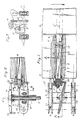
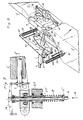
claim 1 and, in preferred embodiments, the features stated in claims 2-15. - The invention will now be described in more detail hereinbelow with reference to the accompanying drawings, in which Fig. 1 is a schematic view of part of a turbine as seen in the direction of the turbine shaft, with certain portions removed to illustrate a regulating and synchronizing device according to the invention operating between the turbine blades via the turbine hub, Fig. 2 is a longitudinal section taken along the line A-A in Fig. 1, Fig. 3 is a cross-section taken along the line B-B in Fig. 2, Figs. 4 and 5 correspond to Figs. 2 and 3, but illustrate the regulating device in a partially outwardly angled position and the turbine blade feathered correspondingly, Fig. 6 is a perspective view of an alternative embodiment in which the synchronizing means generally is rotatable and actively actuable by a push rod and a wire, Fig. 7 illustrates a modified embodiment in which the torsional load acting on the turbine blades is provided by means of a spring which is common to the blades and which acts directly on the actuator means for the device for coordinating the angular displacement of the blades, and Fig. 8, finally, is a perspective view showing an embodiment of the turbine according to Figs. 1-7 supplemented with a device sensing the drive shaft torque and limiting it by acting on the pitch movement via spring-loaded moment arms in cases where a very narrow speed range is required, for instance when connecting a generator directly to the mains.
- The turbine shown only partially in Fig. 1 is used as a wind turbine for driving a load, such as an electric generator, by a
drive shaft 1. The turbine blades, of which only the inner portion of oneblade 2 is shown, are rotatably connected to theturbine hub 3 by means of a respective regulating device comprising atorsion spring 8 coaxially mounted in atubular member 7 which at its radially outer end is connected to therespective turbine blade 2 and extends axially through ahollow blade root 5 serving as a housing for thetubular member 7 and rotatably mounted on the blade shaft 2' by means of one ormore bearings 6. At its radially inner end, theblade root 5 may either be fixedly or, for example as in an embodiment described further on in this specification, pivotally connected to thehub 3. - The housing (blade root) 5 and the
tubular member 7 are axially held together by means of thetorsion spring 8 which is disposed in thehousing 5 and which, in the illustrated embodiment, is in the form of a leaf spring. At its radially outer end, thespring 8 is fixedly connected to the blade shaft 7' by means of aspring attachment 12. Thetube 7, which thus forms a part of the blade shaft, accommodates in its radially inner end portion a spring attachment 11 having a head 11' easily accessible from the hub side and allowing adjustment of the bias of thespring 8 by means of a tool and being lockable by means of alocking nut 24 or similar means against the end of a projection 5'' from the radially inner end of thehousing 5. As far as the regulating device has been described hitherto, it agrees with the regulating device disclosed in Swedish Patent Specifications 387,161 and 426,091 and, as in the known regulating device, thespring 8 forms a torque-transmitting means between theblade 2 and thehub 3, the bias of thespring 8 determining the basic setting of the rotary speed of the turbine shaft. - As described in Patent Specification 387,161, the turbine blade has such a blade profile that this initiates about its aerodynamic centre a nose-dipping moment, pitch moment, substantially independently of the lift acting on the blade when the wind impinges thereon. The blade is so arranged in relation to the common longitudinal axis of the two
parts torsion spring 8 gives rise to a moment acting about the axis of rotation 2' of the blade (Fig. 1). This moment tends to turn the blade about said axis which coincides with the common longitudinal axis of theparts - In the embodiment of Fig. 1 in the above-mentioned patent specifications, there is no rotational connection between the shafts 2' of the turbine blades. In the embodiment according to the present invention illustrated in Figs. 1, 2, 4 and 6, the mutual angular position of the
blades 2 about the geometrical blade axes 2' is however maintained equal synchronously by means of a crank arm andlinkage system link arm 10 and a common synchronizing means 14. Therespective link arm 10 is articulated at one end to the corresponding crank arm 9 and articulated at its other end to the synchronizing means 14. The synchronizing means 14 is so arranged that it coordinates the rotation of the blades about their longitudinal axes or geometrical axes of rotation 2'. To this end, the synchronizing means in an advantageous embodiment is composed ofarms 14 symmetrically projecting from a common centre and rigidly connected to each other at their radially inner ends, e.g. by being designed as an integral unit. In the area of this centre, the synchronizingarms 14 are movably supported in relation to a common geometrical axis 4' extending at right angles to the longitudinal axes of thearms 14. In the illustrated embodiments, the geometrical axis 4' is formed of the longitudinal axis of arod 4 which extends coaxially through thehollow drive shaft 1 and on one outer end portion of which the synchronizingmeans 14 is carried. For synchronizing the rotation of twoblades 2, the synchronizing means 14 may have the form of a two-armed yoke. Depending on the arrangement of the crank arm and link arm system, the synchronizing means can be rotatably and/or displaceably arranged in relation to, i.e. about and along, respectively, the geometrical axis 4'. In the embodiment according to Figs. 1-5, thesynchronizing means 14 is displaceable together with therod 4 which, in this case, is displaceably and optionally rotatably mounted in thedrive shaft 1. In the embodiment according to Fig. 6, thesynchronizing means 14 is rotatably mounted on thedrive shaft 1 and so, therod 4 need only be displaceably mounted in thedrive shaft 1. - In the basic setting position of the
blades 2, the synchronizing means 14, or optionally therod 4, bears on an abutment. In Figs. 2 and 4, this abutment is in the form of an elastic shock-absorbingring 15 connected to therod 4 and/or the synchronizing means 14 and arranged to cooperate with anabutment 13 connected to thedrive shaft 1. The engagement of the synchronizing means 14 against or its distance from said dampeningring 15 is dependent upon a spring bias and a force initiated by the aerodynamic moment acting on theturbine blades 2. Thus, in the invention it has become possible to reduce the number of abutments to a single, centrally located abutment which is easily accessible from the hub centre. - In the motion-transmitting
system link arm 10 or any part which transmits rotary movements from one turbine blade to another, as an elastic or otherwise dampening means to allow a certain individual rotational movement of the turbine blades. - When the wind force increases from a certain threshold value, the
turbine blade 2 is turned about its longitudinal axis 2' by the torque determined by the wind force, as well as the size and shape of the blade, where an important factor is the curvature of the blade mean chord. - The rotation of the blade about its geometrical axis 2' upon an increase of the wind force is effected against the action of the elastic torque from the
biased spring 8. The moment characteristics of theturbine blade 2 and thespring 8 have been so selected that the rotary speed of the turbine is maintained substantially constant above said wind-force threshold value up to a considerably higher wind-force value, at and above which the rotary speed of the turbine again starts to decrease because the aerodynamic moment of theturbine blade 2 above said threshold value increases more rapidly than the torsion torque. This is described in the above-mentioned Patent Specification 387,161. - As appears from the above and as illustrated in Figs. 1 and 2, the
torsion spring 8 according to the invention can be biased or tensioned by means of an easily accessible screw 11, 11' which at the same time forms the radially inner spring attachment 11 and can be fixed in the locked position by means of thenut 24. In an alternative embodiment (not shown), it is conceivable to tension or untension thetorsion spring 8, for instance by remote-controlled means, for achieving a start and stop function, i.e. when it is desired to start or stop the turbine. When the turbine has been started, it is possible, as mentioned above, to set the desired speed of rotation. - Figs. 4 and 5 show a
turbine blade 2 which has rotated out of the basic setting position (shown in Fig. 3) to a partially feathered position as shown in Fig. 5, either because the aerodynamic moment of theturbine blade 2, in the event of excessive wind force, has been able to rotate theblade 2 against the action of thetorsion spring 8 or because anexternal force 16 has been able to do so, whereby thesynchronizing yoke 14 has been displaced in the direction of the longitudinal axis of thepush rod 4 away from theabutment 13. The arrangement is such that it is also possible, by means of anexternal force 16, to displace therod 4 acting on thesynchronizing yoke 14, thelink arm 10 and the crank arm 9, so as to rotate theturbine blade 2 against the action of thetorsion spring 8, such that the turbine can be easily stopped also actively, i.e. by intentional influence. In this case, the screw 11, 11', i.e. the spring attachment, need not be used as a means for starting and stopping the turbine. - Further, it is possible by means of an
additional spring 25 disposed, for instance, between thehousing 5 and the crank arm 9 and shown only in Fig. 5, to act on the torsion torque against or with the aerodynamic moment of the turbine blade in a progressive manner, i.e. in a non-linear direction, e.g. for ensuring a more distinct shut-off function, i.e. stopping the turbine in the event of highly excessive wind force. - In Fig. 6, there is shown an alternative embodiment in which the
synchronizing yoke 14 substantially is rotatably mounted about theturbine drive shaft 1, but connected to the blade shaft 2' in a manner similar to that described above for thelink arm 10 and the crank arm 9. In this case, the turbine can also be stopped actively by anexternal force 16 via therod 4 which, in this case, is not fixedly connected to the synchronizingyoke 14 but to whose outer end awire 18 is so connected that theforce 16 can be transmitted to the crank arm 9 viapulleys 19. Naturally, it is possible, via other remote-controlled regulating means, to rotate the blade shaft, either directly or via the crank arm 9. - In the patent specifications earlier mentioned, the flapping movement has been made possible by a resilient portion of the blade root, and in Patent Specification 426,091, Fig. 6 shows an embodiment with so-called flapping articulations in which the limitation of motion is however brought about by means of a resilient abutment against the hub portion.
- According to the present invention, the rotation of the
blade 2 about its geometrical axis of rotation 2' is compatible with the flapping motion of the blade in relation to thehub 3 about a flappingaxis 17 in that theblade 2 proper is rotatable with respect to theblade root 5 which is not rotatable together with the blade, but is pivotally connected to thehub 3 for executing a pivotal movement, flapping, within certain limits about the flappingaxis 17. The possible pivotal or flapping movement is limited by flapping bearingsupport arms 22 extending into a hollow part of thehub 3 between motion-limitingabutments 21. - It appears from the above that synchronization, i.e. coordination, of the angular motion and angular displacement of the blades about their axes of rotation 2' is achieved by relatively simple means, i.e. linkage systems consisting of the crank arms 9 connected to the
rotatable blade portions 2, and thelink arms 10 articulated to the crank arms 9 and hingedly connected to a power-transmitting or power-distributing means 14 which is centrally disposed in relation to the linkage systems and which in the illustrated embodiment for two turbine blades has the form of a two-armed yoke. It further appears that these power- and motion-transmitting systems act, via themeans 14, on anelement 4 which, by being subjected to an external force in the direction of thearrow 16, see Figs. 4 and 6, however itself forms a means for acting on the power-distributing means 14 for rotating the turbine blades via the linkage systems against the wind forces for feathering the blades to such an extent that it is easier to stop the turbine, or for adjustments in the event of a high wind force. - The external force in the direction of the
arrow 16 can be provided by means of an actuator (not shown) which may be controlled, e.g. electronically, in dependence upon selected parameters (wind force, prevailing torque, time etc.), or manually by a mechanical device of any suitable type. - The spring arrangement shown in Fig. 7 for biasing the turbine blades where only one blade shaft 2' is shown in Fig. 7, consists of a helical spring 8' disposed on the actuator means (the rod) 4 and acting between a preferably axially adjustable abutment 11' on the actuator means 4 and an abutment 27' on the
turbine shaft 1. In this embodiment, there are no torsion springs 8 of the type shown in Fig. 2 or any arrangement as described above for pre-setting the torsion springs, but otherwise the embodiment in Fig. 7 corresponds to that in Fig. 2. - It appears from Fig. 7 that the powerful spring 8' acts, by the actuator means (the rod) 4, on the device for coordinating the angular motion and angular displacement of the
turbine blades 2 about their axes of rotation 2', i.e. the spring acts on the actuator means 4 and, via this means 4, on the power-transmittingmeans 14 and, via thelink arms 10, on the blade shafts 2'. - The spring arrangement acting on the blades, i.e. the torsion springs 8 in Figs. 1-6 and the helical spring 8' in Fig. 7, may of course be modified in several other ways than described above and illustrated in the drawings without departing from the inventive concept.
- The moment-sensing device shown in Fig. 8 comprises the
drive shaft 1 with adriver yoke 30 fixed thereto, and the drive shaft front end 31 which is rotatably mounted in thehub 3. Twomoment arms 32, one for eachturbine blade 2, are connected to thedriver yoke 30 by arespective link arm 33 in points 34 and 35 and to thehub 3 inpoints 36 by means of arespective pin 37 in ahole 38. Twobiased springs 39 are connected at their ends to thehub 3 inlugs 40 thereon and to theouter end 41 of the associatedmoment arm 32. Twodrivers 42 in the form of flexible lines or the like are connected at their ends to arespective moment arm 32 and to a respective crank arm 9. In the illustrated embodiment, the crank arms have a projecting fixing point 43 for oneend 44 of therespective driver 42. - As appears from Fig. 8, the driving force from the
hub 3 rotatably mounted on thedrive shaft 1 is transmitted via the moment arm fixing points 36 to therespective moment arm 32 at thebearing biased spring 39 in the associatedmoment arm 32 at theend 41. - As appears from Fig. 8, the
spring 39 is extended when the force exerted at theend 41 of themoment arm 32 exceeds the bias of the spring, which occurs when the desired maximum driving moment is attained. As in the illustrated case, themoment arm 32 then acts via thedriver 42 at the fixing point 43 of the crank arm 9 on the pitch shaft 2', such that theturbine blade 2 can rotate in a direction towards a reduced driving moment.
Claims (13)
- A turbine regulating device for maintaining constant rotary speed comprising a turbine hub (3), a plurality of turbine blades (2) supported by and rotatably connected to said hub, said turbine blades (2) arranged and constructed to apply a torque acting about a turbine shaft (1), a spring arrangement (8; 8') arranged and constructed to rotate said turbine blade about a longitudinal geometrical axis of rotation (2') substantially at right angles to said turbine shaft (1), a spring arrangement biasing means (11; 11') arranged and constructed to oppose a torque applied to said turbine blade by flowing fluid, said blade having a blade profile arranged and constructed to generate a pitch movement, said pitch movement being determined by said blade profile and being substantially independent of blade lift, an actuator means (4), a power transmitting means (14) operable by said actuator means and moveably supported with respect to said hub (3), said power transmitting means arranged and constructed to coordinate angular motion and displacement of said turbine blades (2) about said axis of rotation (2') of said blades, characterized by a linkage system (9) connecting said power transmitting means (14) with said turbine blades (2), said linkage system having a crank arm (9) connected to each turbine blade, said linkage system (9) and power transmitting means (14) being arranged and constructed to rotate all turbine blades (2) around their geometrical axis through an angular displacement substantially equal to a rotated turbine blade, and by abutment means having a resilient abutment (15) and a fixed abutment (13), said resilient abutment (15) being carried by said power transmitting means (14) and being moveably arranged with respect to said hub (3), said fixed abutment (13) being fixedly supported with respect to said turbine hub and being arranged and constructed to cooperate with said resilient abutment and to accept reaction forces from said spring arrangement (8; 8') via said power transmitting means (14), whereby a force acts on said actuator means (14) and on said turbine blades (2) via said power transmitting means (14) and said linkage system (9).
- A regulating device according to Claim 1, wherein said actuator means (4) is rod shaped, and said actuator means is arranged and constructed to be coaxially displaceable and rotatable with respect to said turbine hub (3), whereby said turbine blades (2) are rotatable by the actuator means (4) via said power transmitting means (14) and said linkage system (9).
- A regulating device according to Claim 1, wherein said power transmitting means is a multi-arm power distributing yoke (14), said yoke having one arm for each one turbine blade (2) and being supported at its center by said actuator means (4).
- A regulating device according to Claim 1, further comprising an adjustable lockable set screw spring attachment (11), whereby each turbine blade (2) is connected to said hub (3) by said spring attachment.
- A regulating device according to Claim 1, further comprising a geometric flapping axis (17) around which said blades (2) rotate with respect to said turbine hub (3).
- A regulating device according to Claim 1, wherein the geometric axis of rotation (4') of said turbine shaft (1) and a geometric flapping axis (17) perpendicular to said turbine shaft (1) are disposed in different planes, whereby as the bending moment on a blade shaft is decreased, geometry is improved, and a larger area for power distributing is achieved.
- A regulating device according to Claim 1, further comprising resilient link arms (10) connecting said crank arms (9) with said power transmitting means (14).
- A regulating device according to claim 1, further comprising a resilient means (25) arranged and constructed to act between said crank arm (9) and a part (5) connected to said hub (3), whereby a moment is progressively applied to said spring arrangement (8).
- A regulating device according to Claim 1, wherein said power transmitting means has a power distributing arm (14), and a link arm (12) is disposed between said crank arm (9) and said power distributing arm (14), a portion of said link arm (10) being elastically deformable in a direction along said power distributing arm (14).
- A regulating device according to Claim 1, further comprising at least one flapping bearing support arm (22) connecting a blade root (5') to said hub (3), and two motion-limiting abutments (21) connected to said hub, said support arm (22) extending past a geometric flapping axis (17) between said motion limiting abutments (21).
- A regulating device according to Claim 1, further comprising a moment sensing device (30-44), said hub (3) being rotatably connected to said turbine shaft (1), whereby twisting of said turbine (1) shaft acts upon said moment sensing device (30-44) to twist said turbine blades (2).
- A regulating device according to Claim 11, wherein said moment sensing device comprises moment arms (32), a driver yoke (30) fixed on said drive shaft (1), link arms (33) connecting said moment arms (32) to said yoke (30) and said hub (3), and drivers (42) connected to said moment arms (32) and said crank arm (9).
- A regulating device according to Claim 12, further comprising biased springs (39) connected to said hub (3) and to said moment arm (32).
Priority Applications (1)
| Application Number | Priority Date | Filing Date | Title |
|---|---|---|---|
| AT88907858T ATE90775T1 (en) | 1987-09-15 | 1988-09-08 | CONTROL ARRANGEMENT FOR KEEPING ROTATIONAL SPEED CONSTANT IN TURBINES. |
Applications Claiming Priority (2)
| Application Number | Priority Date | Filing Date | Title |
|---|---|---|---|
| SE8703565A SE458293B (en) | 1987-09-15 | 1987-09-15 | CONTROL DEVICE FOR CONSUMPTION OF TURBIN SPEED |
| SE8703565 | 1987-09-15 |
Publications (2)
| Publication Number | Publication Date |
|---|---|
| EP0377629A1 EP0377629A1 (en) | 1990-07-18 |
| EP0377629B1 true EP0377629B1 (en) | 1993-06-16 |
Family
ID=20369574
Family Applications (1)
| Application Number | Title | Priority Date | Filing Date |
|---|---|---|---|
| EP88907858A Expired - Lifetime EP0377629B1 (en) | 1987-09-15 | 1988-09-08 | Regulating device for maintaining constant the rotary speed in turbines |
Country Status (13)
| Country | Link |
|---|---|
| US (1) | US5096381A (en) |
| EP (1) | EP0377629B1 (en) |
| JP (1) | JPH03502594A (en) |
| CN (1) | CN1020496C (en) |
| AT (1) | ATE90775T1 (en) |
| AU (1) | AU619494B2 (en) |
| CA (1) | CA1286609C (en) |
| DE (1) | DE3881893T2 (en) |
| ES (1) | ES2010361A6 (en) |
| GR (1) | GR1000411B (en) |
| IN (1) | IN169700B (en) |
| SE (1) | SE458293B (en) |
| WO (1) | WO1989002531A1 (en) |
Families Citing this family (23)
| Publication number | Priority date | Publication date | Assignee | Title |
|---|---|---|---|---|
| US5297934A (en) * | 1991-08-02 | 1994-03-29 | The Boeing Company | Compensation for kinematic foreshortening effect in pitch control system for rotary wing aircraft |
| AU2551792A (en) * | 1991-08-02 | 1993-03-02 | Boeing Company, The | Ducted tail rotor for rotary wing aircraft providing torque reaction and yaw attitude control |
| CA2113719C (en) * | 1991-08-02 | 1999-11-02 | Rene A. Desjardins | Ducted fan and pitch controls for tail rotor of rotary wing aircraft |
| FR2686656B1 (en) * | 1992-01-29 | 1994-03-18 | Alain Troncy | REGULATION SYSTEM FOR VARIABLE STEP PROPELLERS. |
| NL9401655A (en) * | 1994-10-07 | 1996-05-01 | Stork Prod Eng | Wind turbine with passive control. |
| US6327957B1 (en) * | 1998-01-09 | 2001-12-11 | Wind Eagle Joint Venture | Wind-driven electric generator apparatus of the downwind type with flexible changeable-pitch blades |
| ES2289082T3 (en) * | 2002-02-25 | 2008-02-01 | Iskra Wind Turbines Ltd. | PASSIVE SPEED AND POWER REGULATION OF A WIND TURBINE. |
| US7381029B2 (en) * | 2004-09-30 | 2008-06-03 | General Electric Company | Multi-piece wind turbine rotor blades and wind turbines incorporating same |
| DK200500899A (en) * | 2005-06-17 | 2006-12-18 | Lm Glasfiber As | Wing with hinged wing tip |
| US7690895B2 (en) * | 2005-07-29 | 2010-04-06 | General Electric Company | Multi-piece passive load reducing blades and wind turbines using same |
| US7568888B2 (en) * | 2006-10-24 | 2009-08-04 | Gm Global Technology Operations, Inc. | Fan blades having variable pitch compliantly responsive to a linear actuator |
| EP2000667B1 (en) * | 2007-06-04 | 2011-08-10 | Siemens Aktiengesellschaft | Method and device for controlling load reduction for a wind turbine rotor |
| US20090148285A1 (en) * | 2007-12-06 | 2009-06-11 | General Electric Company | Multi-section wind turbine rotor blades and wind turbines incorporating same |
| US20090148291A1 (en) * | 2007-12-06 | 2009-06-11 | General Electric Company | Multi-section wind turbine rotor blades and wind turbines incorporating same |
| WO2010018631A1 (en) * | 2008-08-14 | 2010-02-18 | 三菱重工業株式会社 | Wind turbine generator |
| US7719128B2 (en) * | 2008-09-30 | 2010-05-18 | General Electric Company | System and method for controlling a wind turbine during loss of grid power and changing wind conditions |
| US8334610B2 (en) * | 2009-02-13 | 2012-12-18 | Robert Migliori | Gearless pitch control mechanism for starting, stopping and regulating the power output of wind turbines without the use of a brake |
| DE102009037237A1 (en) * | 2009-08-12 | 2011-02-17 | Repower Systems Ag | Method and arrangement for automatic configuration parameter control in wind turbines |
| WO2012112892A2 (en) * | 2011-02-18 | 2012-08-23 | Concepts Eti, Inc. | Turbomachinery having self-articulating blades, shutter valve, partial-admission shutters, and/or variable-pitch inlet nozzles |
| CN103670941B (en) * | 2014-01-09 | 2016-02-03 | 天津市职业大学 | A kind of feather vertical axis aerogenerator |
| CN104500339B (en) * | 2014-11-14 | 2017-05-17 | 天津市职业大学 | Blade distance adjusting mechanism of horizontal-axis wind turbine |
| US20180291761A1 (en) * | 2015-05-27 | 2018-10-11 | Hydrospin Monitoring Solutions Ltd. | Energy generating system and method |
| CN105443301B (en) * | 2015-11-25 | 2017-12-05 | 中国石油集团钻井工程技术研究院 | Down-hole turbogenerator for measurement while drilling |
Citations (1)
| Publication number | Priority date | Publication date | Assignee | Title |
|---|---|---|---|---|
| DE904400C (en) * | 1951-08-12 | 1954-02-18 | Fritz Huebner | Wind turbine with adjustable blades |
Family Cites Families (21)
| Publication number | Priority date | Publication date | Assignee | Title |
|---|---|---|---|---|
| US213960A (en) * | 1879-04-01 | Improvement in windmills | ||
| US488087A (en) * | 1892-12-13 | Windmill | ||
| US498068A (en) * | 1893-05-23 | lonningk | ||
| US463025A (en) * | 1891-11-10 | Vaneless wind-engine | ||
| US619954A (en) * | 1899-02-21 | Windmill | ||
| US723293A (en) * | 1902-02-11 | 1903-03-24 | John J Middlesworth | Windmill. |
| US1133595A (en) * | 1914-01-24 | 1915-03-30 | Frederick Wenger | Windmill. |
| US1140221A (en) * | 1914-05-16 | 1915-05-18 | William Weiner | Windmill. |
| US1558645A (en) * | 1924-05-17 | 1925-10-27 | Terhorst Harvey | Windmill |
| SE387161B (en) * | 1975-05-12 | 1976-08-30 | Svenning Sven Konsult Ab | AUTOMATIC SPEED CONTROL DEVICE FOR WIND-OPERATED PROPELLERS |
| DE2825061C2 (en) * | 1978-06-08 | 1981-09-24 | M.A.N. Maschinenfabrik Augsburg-Nürnberg AG, 8000 München | windmill |
| EP0009052A1 (en) * | 1978-08-17 | 1980-04-02 | Messerschmitt-Bölkow-Blohm Gesellschaft mit beschränkter Haftung | Aerodynamically self-governed wind turbine |
| US4193005A (en) * | 1978-08-17 | 1980-03-11 | United Technologies Corporation | Multi-mode control system for wind turbines |
| AU5724480A (en) * | 1979-04-23 | 1980-10-30 | Maschinenfabrik Augsburg-Nurnberg Aktiengesellschaft | Wind motor vane pitch control |
| US4431375A (en) * | 1979-05-10 | 1984-02-14 | Carter Wind Power | Wind-driven generator apparatus |
| US4310284A (en) * | 1979-08-27 | 1982-01-12 | Randolph Arthur J | Automatically controlled wind propeller and tower shadow eliminator |
| CA1146079A (en) * | 1980-03-17 | 1983-05-10 | Edward H. Kusiak | Wind turbine blade pitch adjustment system |
| FR2519710B1 (en) * | 1982-01-11 | 1986-08-08 | Bernard Jean | REGULATION AND SAFETY DEVICE FOR THE OPERATION AND MAINTENANCE OF HORIZONTAL WIND TURBINE |
| SE8200140L (en) * | 1982-01-13 | 1982-12-06 | Svenning Konsult Ab S | CONTROL DEVICE FOR CONSTANT HALLING OF SPEED AT WIND-DRIVEN PROPELLERS |
| FR2569243B1 (en) * | 1984-08-17 | 1988-12-30 | Aubertin Edouard | VARIABLE STEP PROPELLER ROTOR, PARTICULARLY FOR A WIND ENGINE |
| US4678923A (en) * | 1985-11-13 | 1987-07-07 | Fernand Trepanier | Windmill |
-
1987
- 1987-09-15 SE SE8703565A patent/SE458293B/en not_active IP Right Cessation
-
1988
- 1988-09-08 DE DE88907858T patent/DE3881893T2/en not_active Expired - Fee Related
- 1988-09-08 JP JP63507380A patent/JPH03502594A/en active Pending
- 1988-09-08 AT AT88907858T patent/ATE90775T1/en active
- 1988-09-08 US US07/466,428 patent/US5096381A/en not_active Expired - Lifetime
- 1988-09-08 EP EP88907858A patent/EP0377629B1/en not_active Expired - Lifetime
- 1988-09-08 WO PCT/SE1988/000457 patent/WO1989002531A1/en not_active Ceased
- 1988-09-08 AU AU24203/88A patent/AU619494B2/en not_active Expired
- 1988-09-13 IN IN769/CAL/88A patent/IN169700B/en unknown
- 1988-09-14 GR GR880100600A patent/GR1000411B/en not_active IP Right Cessation
- 1988-09-14 ES ES8802807A patent/ES2010361A6/en not_active Expired
- 1988-09-14 CA CA000577328A patent/CA1286609C/en not_active Expired - Lifetime
- 1988-09-15 CN CN88107747A patent/CN1020496C/en not_active Expired - Lifetime
Patent Citations (1)
| Publication number | Priority date | Publication date | Assignee | Title |
|---|---|---|---|---|
| DE904400C (en) * | 1951-08-12 | 1954-02-18 | Fritz Huebner | Wind turbine with adjustable blades |
Also Published As
| Publication number | Publication date |
|---|---|
| EP0377629A1 (en) | 1990-07-18 |
| SE458293B (en) | 1989-03-13 |
| GR880100600A (en) | 1989-06-22 |
| SE8703565D0 (en) | 1987-09-15 |
| AU2420388A (en) | 1989-04-17 |
| ES2010361A6 (en) | 1989-11-01 |
| ATE90775T1 (en) | 1993-07-15 |
| IN169700B (en) | 1991-12-07 |
| CA1286609C (en) | 1991-07-23 |
| WO1989002531A1 (en) | 1989-03-23 |
| DE3881893D1 (en) | 1993-07-22 |
| AU619494B2 (en) | 1992-01-30 |
| US5096381A (en) | 1992-03-17 |
| JPH03502594A (en) | 1991-06-13 |
| GR1000411B (en) | 1992-06-30 |
| DE3881893T2 (en) | 1993-10-28 |
| CN1020496C (en) | 1993-05-05 |
| CN1032835A (en) | 1989-05-10 |
Similar Documents
| Publication | Publication Date | Title |
|---|---|---|
| US5096381A (en) | Regulating device for maintaining constant the rotary speed in turbines | |
| US4324528A (en) | Automatic regulating device for keeping constant the speed of wind-powered propellers | |
| US4652208A (en) | Actuating lever for variable stator vanes | |
| WO1996020343A9 (en) | Rotor device and control for wind turbine | |
| EP3495265B1 (en) | A rotor assembly for a rotorcraft with torque controlled collective pitch | |
| GB2041310A (en) | Blade-to-hub connections for helicopter rotors | |
| WO1996020343A2 (en) | Rotor device and control for wind turbine | |
| NL2005954C2 (en) | Wind turbine. | |
| US5487645A (en) | Ram air turbine with secondary governor | |
| EP0025791B1 (en) | A wind turbine | |
| US4439108A (en) | Windmill having centrifically feathered rotors to control rotor speed | |
| EP0159805B1 (en) | Wind turbine operated electrical generator system | |
| CN102926932A (en) | Automatic blade-changing speed-regulating device based on wind speed | |
| WO2004088131A1 (en) | Self-regulating wind turbine | |
| GB1592114A (en) | Rotors preferably for wind power stations | |
| US20060171810A1 (en) | Wind generator of the type with automatic power regulation | |
| JP2508099B2 (en) | Wind power generator | |
| CN2782976Y (en) | Automatic vane adjusting speed limiter for small wind driven power generator | |
| EP0089793B1 (en) | Helicopter rotors | |
| SE505384C2 (en) | Wind turbines | |
| CA1131943A (en) | Infinitely variable transmission | |
| JP2900218B2 (en) | Concrete floor finishing machine | |
| EP0088778A1 (en) | A windmill having automatic pitch control means | |
| WO1981002766A1 (en) | A wind mill rotor with an automatically adjustable angle of inclination | |
| EP1523440A1 (en) | Helicopter |
Legal Events
| Date | Code | Title | Description |
|---|---|---|---|
| PUAI | Public reference made under article 153(3) epc to a published international application that has entered the european phase |
Free format text: ORIGINAL CODE: 0009012 |
|
| 17P | Request for examination filed |
Effective date: 19900307 |
|
| AK | Designated contracting states |
Kind code of ref document: A1 Designated state(s): AT BE CH DE FR GB IT LI LU NL SE |
|
| 17Q | First examination report despatched |
Effective date: 19910621 |
|
| GRAA | (expected) grant |
Free format text: ORIGINAL CODE: 0009210 |
|
| ITF | It: translation for a ep patent filed | ||
| AK | Designated contracting states |
Kind code of ref document: B1 Designated state(s): AT BE CH DE FR GB IT LI LU NL SE |
|
| PG25 | Lapsed in a contracting state [announced via postgrant information from national office to epo] |
Ref country code: LI Effective date: 19930616 Ref country code: FR Effective date: 19930616 Ref country code: CH Effective date: 19930616 Ref country code: SE Effective date: 19930616 Ref country code: BE Effective date: 19930616 Ref country code: AT Effective date: 19930616 |
|
| REF | Corresponds to: |
Ref document number: 90775 Country of ref document: AT Date of ref document: 19930715 Kind code of ref document: T |
|
| REF | Corresponds to: |
Ref document number: 3881893 Country of ref document: DE Date of ref document: 19930722 |
|
| PG25 | Lapsed in a contracting state [announced via postgrant information from national office to epo] |
Ref country code: LU Free format text: LAPSE BECAUSE OF NON-PAYMENT OF DUE FEES Effective date: 19930930 |
|
| REG | Reference to a national code |
Ref country code: CH Ref legal event code: PL |
|
| EN | Fr: translation not filed | ||
| PLBE | No opposition filed within time limit |
Free format text: ORIGINAL CODE: 0009261 |
|
| STAA | Information on the status of an ep patent application or granted ep patent |
Free format text: STATUS: NO OPPOSITION FILED WITHIN TIME LIMIT |
|
| 26N | No opposition filed | ||
| PGFP | Annual fee paid to national office [announced via postgrant information from national office to epo] |
Ref country code: NL Payment date: 19990819 Year of fee payment: 12 |
|
| PGFP | Annual fee paid to national office [announced via postgrant information from national office to epo] |
Ref country code: DE Payment date: 19990820 Year of fee payment: 12 |
|
| PG25 | Lapsed in a contracting state [announced via postgrant information from national office to epo] |
Ref country code: NL Free format text: LAPSE BECAUSE OF NON-PAYMENT OF DUE FEES Effective date: 20010401 |
|
| NLV4 | Nl: lapsed or anulled due to non-payment of the annual fee |
Effective date: 20010401 |
|
| PG25 | Lapsed in a contracting state [announced via postgrant information from national office to epo] |
Ref country code: DE Free format text: LAPSE BECAUSE OF NON-PAYMENT OF DUE FEES Effective date: 20010601 |
|
| REG | Reference to a national code |
Ref country code: GB Ref legal event code: IF02 |
|
| PG25 | Lapsed in a contracting state [announced via postgrant information from national office to epo] |
Ref country code: IT Free format text: LAPSE BECAUSE OF NON-PAYMENT OF DUE FEES;WARNING: LAPSES OF ITALIAN PATENTS WITH EFFECTIVE DATE BEFORE 2007 MAY HAVE OCCURRED AT ANY TIME BEFORE 2007. THE CORRECT EFFECTIVE DATE MAY BE DIFFERENT FROM THE ONE RECORDED. Effective date: 20050908 |
|
| PGFP | Annual fee paid to national office [announced via postgrant information from national office to epo] |
Ref country code: GB Payment date: 20070914 Year of fee payment: 20 |
|
| REG | Reference to a national code |
Ref country code: GB Ref legal event code: PE20 Expiry date: 20080907 |
|
| PG25 | Lapsed in a contracting state [announced via postgrant information from national office to epo] |
Ref country code: GB Free format text: LAPSE BECAUSE OF EXPIRATION OF PROTECTION Effective date: 20080907 |